2002 JEEP GRAND CHEROKEE 4.0
[x] Cancel search: 4.0Page 238 of 2199

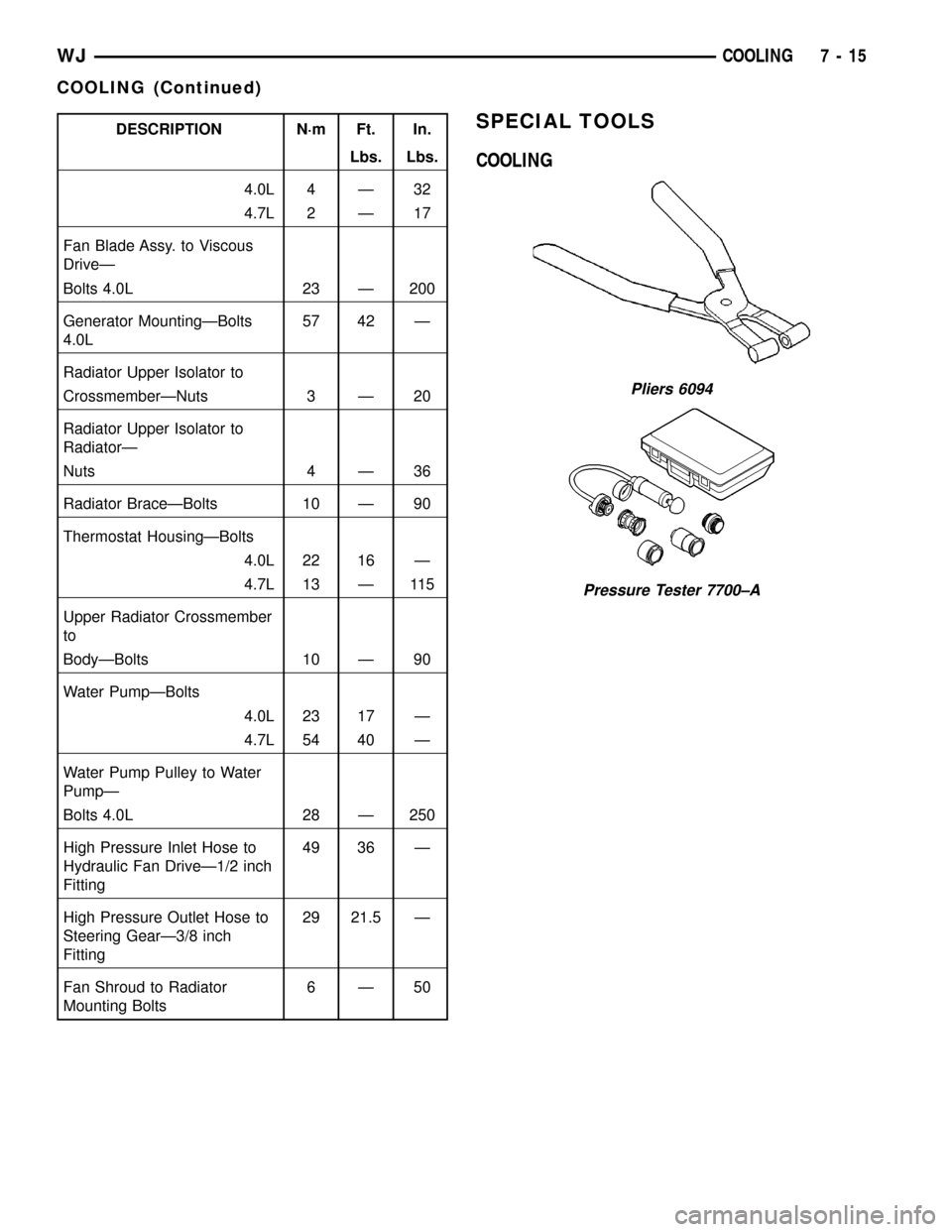
DESCRIPTION N´m Ft. In.
Lbs. Lbs.
4.0L 4 Ð 32
4.7L 2 Ð 17
Fan Blade Assy. to Viscous
DriveÐ
Bolts 4.0L 23 Ð 200
Generator MountingÐBolts
4.0L57 42 Ð
Radiator Upper Isolator to
CrossmemberÐNuts 3 Ð 20
Radiator Upper Isolator to
RadiatorÐ
Nuts 4 Ð 36
Radiator BraceÐBolts 10 Ð 90
Thermostat HousingÐBolts
4.0L 22 16 Ð
4.7L 13 Ð 115
Upper Radiator Crossmember
to
BodyÐBolts 10 Ð 90
Water PumpÐBolts
4.0L 23 17 Ð
4.7L 54 40 Ð
Water Pump Pulley to Water
PumpÐ
Bolts 4.0L 28 Ð 250
High Pressure Inlet Hose to
Hydraulic Fan DriveÐ1/2 inch
Fitting49 36 Ð
High Pressure Outlet Hose to
Steering GearÐ3/8 inch
Fitting29 21.5 Ð
Fan Shroud to Radiator
Mounting Bolts6Ð50SPECIAL TOOLS
COOLING
Pliers 6094
Pressure Tester 7700±A
WJCOOLING 7 - 15
COOLING (Continued)
Page 239 of 2199

ACCESSORY DRIVE
TABLE OF CONTENTS
page page
BELT TENSIONERS
REMOVAL
REMOVALÐ4.7L ENGINE...............16
REMOVALÐ4.0L ENGINE...............16
INSTALLATION
INSTALLATIONÐ4.7L ENGINE...........16
INSTALLATIONÐ4.0L ENGINE...........17
DRIVE BELTS - 4.0L
DIAGNOSIS AND TESTING ± SERPENTINE
DRIVE BELT.........................17REMOVALÐ4.0L ENGINE.................19
INSTALLATIONÐ4.0L ENGINE.............19
DRIVE BELTS - 4.7L
DIAGNOSIS AND TESTING ± SERPENTINE
DRIVE BELT.........................20
REMOVAL - 4.7L ENGINE.................22
INSTALLATION - 4.7L ENGINE.............23
BELT TENSIONERS
REMOVAL
REMOVALÐ4.7L ENGINE
(1) Remove accessory drive belt (Refer to 7 -
COOLING/ACCESSORY DRIVE/DRIVE BELTS -
REMOVAL).
(2) Remove tensioner assembly from engine front
cover (Fig. 1).
WARNING: BECAUSE OF HIGH SPRING TENSION,
DO NOT ATTEMPT TO DISASSEMBLE AUTOMATIC
TENSIONER. UNIT IS SERVICED AS AN ASSEMBLY
(EXCEPT FOR PULLEY ON TENSIONER).
(3) Remove pulley bolt. Remove pulley from ten-
sioner.
REMOVALÐ4.0L ENGINE
(1) Remove accessory drive belt (Refer to 7 -
COOLING/ACCESSORY DRIVE/DRIVE BELTS -
REMOVAL).
(2) Remove tensioner assembly from mounting
bracket (Fig. 2).
WARNING: BECAUSE OF HIGH SPRING TENSION,
DO NOT ATTEMPT TO DISASSEMBLE AUTOMATIC
TENSIONER. UNIT IS SERVICED AS AN ASSEMBLY.
INSTALLATION
INSTALLATIONÐ4.7L ENGINE
(1) Install pulley and pulley bolt to tensioner.
Tighten bolt to 61 N´m (45 ft. lbs.) torque.
(2) An indexing slot is located on back of tensioner.
Align this slot to the head of the bolt on the front
cover. Install the mounting bolt. Tighten bolt to 41
N´m (30 ft. lbs.).
Fig. 1 Automatic Belt Tensioner
1 - TIMING CHAIN COVER
2 - BOLT TORQUE TO 41 N´m (30 FT LBS)
3 - AUTOMATIC BELT TENSIONER
7 - 16 ACCESSORY DRIVEWJ
Page 240 of 2199

(3) Install drive belt (Refer to 7 - COOLING/AC-
CESSORY DRIVE/DRIVE BELTS - INSTALLA-
TION).
(4) Check belt indexing marks (Refer to 7 - COOL-
ING/ACCESSORY DRIVE/DRIVE BELTS - INSTAL-
LATION).
INSTALLATIONÐ4.0L ENGINE
(1) Install tensioner assembly to mounting
bracket, align the two dowels on the tensioner with
the mounting bracket and hand start the bolt.
Tighten bolt to 28 N´m (250 in. lbs.).
CAUTION: To prevent damage to coil case, coil
mounting bolts must be torqued.
(2) Install drive belt. (Refer to 7 - COOLING/AC-
CESSORY DRIVE/DRIVE BELTS - INSTALLA-
TION).(3) Check belt indexing marks (Refer to 7 - COOL-
ING/ACCESSORY DRIVE/DRIVE BELTS - INSTAL-
LATION).
DRIVE BELTS - 4.0L
DIAGNOSIS AND TESTING ± SERPENTINE
DRIVE BELT
When diagnosing serpentine drive belts, small
cracks that run across ribbed surface of belt from rib
to rib (Fig. 3), are considered normal. These are not a
reason to replace belt. However, cracks running along
a rib (not across) arenotnormal. Any belt with
cracks running along a rib must be replaced (Fig. 3).
Also replace belt if it has excessive wear, frayed cords
or severe glazing.
Refer to SERPENTINE DRIVE BELT DIAGNOSIS
CHART for further belt diagnosis.
Fig. 2 Automatic Belt Tensioner
1 - IDLER PULLEY TIGHTEN TO 47 N´m (35 FT. LBS.)
2 - AUTOMATIC BELT TENSIONER
3 - GENERATOR MOUNTING BRACKET
Fig. 3 Serpentine Accessory Drive Belt Wear
Patterns
1 - NORMAL CRACKS BELT OK
2 - NOT NORMAL CRACKS REPLACE BELT
WJACCESSORY DRIVE 7 - 17
BELT TENSIONERS (Continued)
Page 241 of 2199

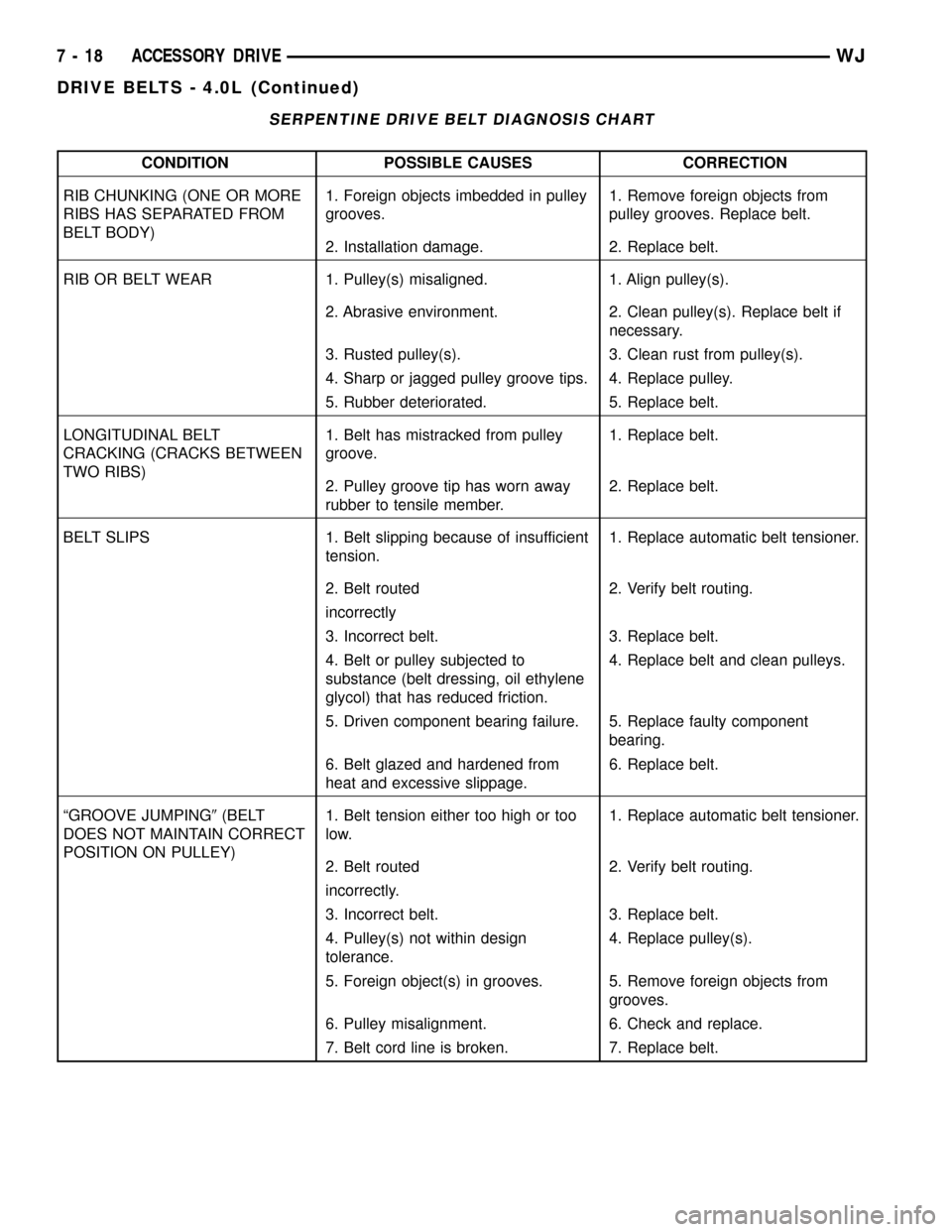
SERPENTINE DRIVE BELT DIAGNOSIS CHART
CONDITION POSSIBLE CAUSES CORRECTION
RIB CHUNKING (ONE OR MORE
RIBS HAS SEPARATED FROM
BELT BODY)1. Foreign objects imbedded in pulley
grooves.1. Remove foreign objects from
pulley grooves. Replace belt.
2. Installation damage. 2. Replace belt.
RIB OR BELT WEAR 1. Pulley(s) misaligned. 1. Align pulley(s).
2. Abrasive environment. 2. Clean pulley(s). Replace belt if
necessary.
3. Rusted pulley(s). 3. Clean rust from pulley(s).
4. Sharp or jagged pulley groove tips. 4. Replace pulley.
5. Rubber deteriorated. 5. Replace belt.
LONGITUDINAL BELT
CRACKING (CRACKS BETWEEN
TWO RIBS)1. Belt has mistracked from pulley
groove.1. Replace belt.
2. Pulley groove tip has worn away
rubber to tensile member.2. Replace belt.
BELT SLIPS 1. Belt slipping because of insufficient
tension.1. Replace automatic belt tensioner.
2. Belt routed 2. Verify belt routing.
incorrectly
3. Incorrect belt. 3. Replace belt.
4. Belt or pulley subjected to
substance (belt dressing, oil ethylene
glycol) that has reduced friction.4. Replace belt and clean pulleys.
5. Driven component bearing failure. 5. Replace faulty component
bearing.
6. Belt glazed and hardened from
heat and excessive slippage.6. Replace belt.
ªGROOVE JUMPING9(BELT
DOES NOT MAINTAIN CORRECT
POSITION ON PULLEY)1. Belt tension either too high or too
low.1. Replace automatic belt tensioner.
2. Belt routed 2. Verify belt routing.
incorrectly.
3. Incorrect belt. 3. Replace belt.
4. Pulley(s) not within design
tolerance.4. Replace pulley(s).
5. Foreign object(s) in grooves. 5. Remove foreign objects from
grooves.
6. Pulley misalignment. 6. Check and replace.
7. Belt cord line is broken. 7. Replace belt.
7 - 18 ACCESSORY DRIVEWJ
DRIVE BELTS - 4.0L (Continued)
Page 242 of 2199

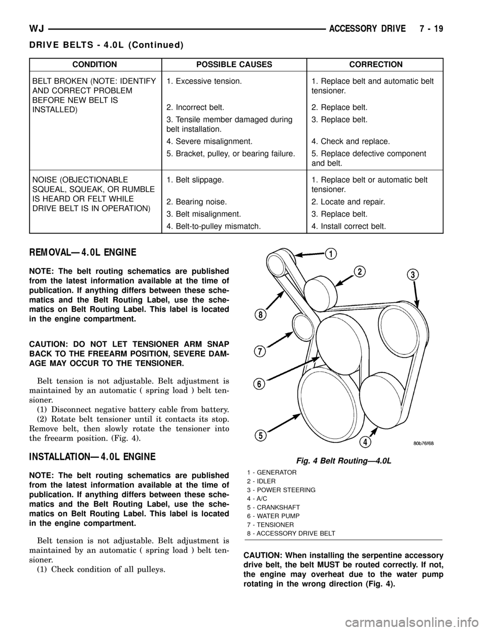
CONDITION POSSIBLE CAUSES CORRECTION
BELT BROKEN (NOTE: IDENTIFY
AND CORRECT PROBLEM
BEFORE NEW BELT IS
INSTALLED)1. Excessive tension. 1. Replace belt and automatic belt
tensioner.
2. Incorrect belt. 2. Replace belt.
3. Tensile member damaged during
belt installation.3. Replace belt.
4. Severe misalignment. 4. Check and replace.
5. Bracket, pulley, or bearing failure. 5. Replace defective component
and belt.
NOISE (OBJECTIONABLE
SQUEAL, SQUEAK, OR RUMBLE
IS HEARD OR FELT WHILE
DRIVE BELT IS IN OPERATION)1. Belt slippage. 1. Replace belt or automatic belt
tensioner.
2. Bearing noise. 2. Locate and repair.
3. Belt misalignment. 3. Replace belt.
4. Belt-to-pulley mismatch. 4. Install correct belt.
REMOVALÐ4.0L ENGINE
NOTE: The belt routing schematics are published
from the latest information available at the time of
publication. If anything differs between these sche-
matics and the Belt Routing Label, use the sche-
matics on Belt Routing Label. This label is located
in the engine compartment.
CAUTION: DO NOT LET TENSIONER ARM SNAP
BACK TO THE FREEARM POSITION, SEVERE DAM-
AGE MAY OCCUR TO THE TENSIONER.
Belt tension is not adjustable. Belt adjustment is
maintained by an automatic ( spring load ) belt ten-
sioner.
(1) Disconnect negative battery cable from battery.
(2) Rotate belt tensioner until it contacts its stop.
Remove belt, then slowly rotate the tensioner into
the freearm position. (Fig. 4).
INSTALLATIONÐ4.0L ENGINE
NOTE: The belt routing schematics are published
from the latest information available at the time of
publication. If anything differs between these sche-
matics and the Belt Routing Label, use the sche-
matics on Belt Routing Label. This label is located
in the engine compartment.
Belt tension is not adjustable. Belt adjustment is
maintained by an automatic ( spring load ) belt ten-
sioner.
(1) Check condition of all pulleys.CAUTION: When installing the serpentine accessory
drive belt, the belt MUST be routed correctly. If not,
the engine may overheat due to the water pump
rotating in the wrong direction (Fig. 4).
Fig. 4 Belt RoutingÐ4.0L
1 - GENERATOR
2 - IDLER
3 - POWER STEERING
4 - A/C
5 - CRANKSHAFT
6 - WATER PUMP
7 - TENSIONER
8 - ACCESSORY DRIVE BELT
WJACCESSORY DRIVE 7 - 19
DRIVE BELTS - 4.0L (Continued)
Page 243 of 2199

(2) Install new belt (Fig. 4). Route the belt around
all pulleys except the idler pulley. Rotate the ten-
sioner arm until it contacts its stop position. Route
the belt around the idler and slowly let the tensioner
rotate into the belt. Make sure the belt is seated onto
all pulleys.
(3) With the drive belt installed, inspect the belt
wear indicator (Fig. 5). On 4.0L Engines, the indica-
tor mark must be between the minimum and maxi-
mum marks. If the measurement exceedes this
specification replace the serpentine accessory drive
belt.DRIVE BELTS - 4.7L
DIAGNOSIS AND TESTING ± SERPENTINE
DRIVE BELT
When diagnosing serpentine drive belts, small
cracks that run across ribbed surface of belt from rib
to rib (Fig. 6), are considered normal. These are not a
reason to replace belt. However, cracks running along
a rib (not across) arenotnormal. Any belt with
cracks running along a rib must be replaced (Fig. 6).
Also replace belt if it has excessive wear, frayed cords
or severe glazing.
Refer to SERPENTINE DRIVE BELT DIAGNOSIS
CHART for further belt diagnosis.
Fig. 5 Accessory Drive Belt Wear Indicator
1 - INDICATOR MARK
2 - MINIMUM TENSION MARK
3 - MAXIMUM TENSION MARK
Fig. 6 Serpentine Accessory Drive Belt Wear
Patterns
1 - NORMAL CRACKS BELT OK
2 - NOT NORMAL CRACKS REPLACE BELT
7 - 20 ACCESSORY DRIVEWJ
DRIVE BELTS - 4.0L (Continued)
Page 247 of 2199

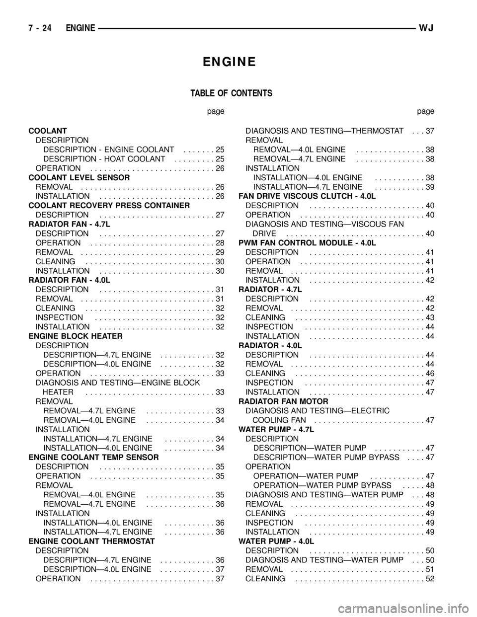
ENGINE
TABLE OF CONTENTS
page page
COOLANT
DESCRIPTION
DESCRIPTION - ENGINE COOLANT.......25
DESCRIPTION - HOAT COOLANT.........25
OPERATION...........................26
COOLANT LEVEL SENSOR
REMOVAL.............................26
INSTALLATION.........................26
COOLANT RECOVERY PRESS CONTAINER
DESCRIPTION.........................27
RADIATOR FAN - 4.7L
DESCRIPTION.........................27
OPERATION...........................28
REMOVAL.............................29
CLEANING............................30
INSTALLATION.........................30
RADIATOR FAN - 4.0L
DESCRIPTION.........................31
REMOVAL.............................31
CLEANING............................32
INSPECTION..........................32
INSTALLATION.........................32
ENGINE BLOCK HEATER
DESCRIPTION
DESCRIPTIONÐ4.7L ENGINE............32
DESCRIPTIONÐ4.0L ENGINE............32
OPERATION...........................33
DIAGNOSIS AND TESTINGÐENGINE BLOCK
HEATER ............................33
REMOVAL
REMOVALÐ4.7L ENGINE...............33
REMOVALÐ4.0L ENGINE...............34
INSTALLATION
INSTALLATIONÐ4.7L ENGINE...........34
INSTALLATIONÐ4.0L ENGINE...........34
ENGINE COOLANT TEMP SENSOR
DESCRIPTION.........................35
OPERATION...........................35
REMOVAL
REMOVALÐ4.0L ENGINE...............35
REMOVALÐ4.7L ENGINE...............36
INSTALLATION
INSTALLATIONÐ4.0L ENGINE...........36
INSTALLATIONÐ4.7L ENGINE...........36
ENGINE COOLANT THERMOSTAT
DESCRIPTION
DESCRIPTIONÐ4.7L ENGINE............36
DESCRIPTIONÐ4.0L ENGINE............37
OPERATION...........................37DIAGNOSIS AND TESTINGÐTHERMOSTAT . . . 37
REMOVAL
REMOVALÐ4.0L ENGINE...............38
REMOVALÐ4.7L ENGINE...............38
INSTALLATION
INSTALLATIONÐ4.0L ENGINE...........38
INSTALLATIONÐ4.7L ENGINE...........39
FAN DRIVE VISCOUS CLUTCH - 4.0L
DESCRIPTION.........................40
OPERATION...........................40
DIAGNOSIS AND TESTINGÐVISCOUS FAN
DRIVE..............................40
PWM FAN CONTROL MODULE - 4.0L
DESCRIPTION.........................41
OPERATION...........................41
REMOVAL.............................41
INSTALLATION.........................42
RADIATOR - 4.7L
DESCRIPTION.........................42
REMOVAL.............................42
CLEANING............................43
INSPECTION..........................44
INSTALLATION.........................44
RADIATOR - 4.0L
DESCRIPTION.........................44
REMOVAL.............................44
CLEANING............................46
INSPECTION..........................47
INSTALLATION.........................47
RADIATOR FAN MOTOR
DIAGNOSIS AND TESTINGÐELECTRIC
COOLING FAN........................47
WATER PUMP - 4.7L
DESCRIPTION
DESCRIPTIONÐWATER PUMP...........47
DESCRIPTIONÐWATER PUMP BYPASS....47
OPERATION
OPERATIONÐWATER PUMP............47
OPERATIONÐWATER PUMP BYPASS.....48
DIAGNOSIS AND TESTINGÐWATER PUMP . . . 48
REMOVAL.............................49
CLEANING............................49
INSPECTION..........................49
INSTALLATION.........................49
WATER PUMP - 4.0L
DESCRIPTION.........................50
DIAGNOSIS AND TESTINGÐWATER PUMP . . . 50
REMOVAL.............................51
CLEANING............................52
7 - 24 ENGINEWJ
Page 254 of 2199

NOTE: When ever the high pressure line fittings are
removed from the hydraulic fan drive the o-rings
located on the fittings must be replaced.
(7) Lubricate the o-rings on the fittings with power
steering fluid then connect inlet and outlet high pres-
sure lines to fan drive (Fig. 9). Tighten inlet line to
49 N´m (36 ft. lbs.) tighten outlet line to 29 N´m (21.5
ft. lbs.).
(8) Connect low pressure return hose to fan drive
(Fig. 9).
(9) Lower vehicle.
(10) Install radiator upper hose.
(11) Connect electrical connector for hydraulic fan
control solenoid.
(12) Tighten fan shroud upper mounting bolts to 6
N´m (50 in. lbs.).
(13) Refill cooling system (Refer to 7 - COOLING -
STANDARD PROCEDURE).
CAUTION: Do not run engine with power steering
fluid below the full mark in the reservoir. Sever
damage to the hydraulic cooling fan or the engine
can occur.(14) Refill power steering fluid reservoir and bleed
air from steering system (Refer to 19 - STEERING/
PUMP - STANDARD PROCEDURE).
(15) Run engine and check for leaks.
RADIATOR FAN - 4.0L
DESCRIPTION
The radiator cooling fan used on the 4.0L engine is
an hybrid fan design. The hybrid fan system consist
of a low speed viscous driven mechanical fan and a
electrical fan (Fig. 10).
REMOVAL
(1) Disconnect negative battery cable from battery.
(2) The thermal viscous fan drive/fan blade assem-
bly is attached (threaded) to water pump hub shaft.
Remove fan blade/viscous fan drive assembly from
water pump by turning mounting nut counterclock-
wise as viewed from front (Fig. 11). Threads on vis-
cous fan drive areRIGHT HAND.
(3) Do not attempt to remove fan/viscous fan drive
assembly from vehicle at this time.
(4) Do not unbolt fan blade assembly from viscous
fan drive at this time.
(5) Remove fan shroud-to-upper crossmember nuts.
(6) Remove fan shroud and fan blade/viscous fan
drive assembly as a complete unit from vehicle.
Fig. 9 HYDRAULIC LINES/HOSES AND ELECTRICAL
CONNECTOR
1 - LOW PRESSURE RETURN HOSE
2 - HIGH PRESSURE LINE (OUTLET)
3 - HIGH PRESSURE LINE (INLET)
4 - HYDRAULIC FAN DRIVEFig. 10 Radiator Cooling Fan
1 - RADIATOR
2 - ELECTRIC COOLING FAN CONNECTOR
3 - FAN SHROUD
4 - ELECTRIC COOLING FAN
WJENGINE 7 - 31
RADIATOR FAN - 4.7L (Continued)