Page 1799 of 2199

TRANSFER CASE - NV242
TABLE OF CONTENTS
page page
TRANSFER CASE - NV242
DESCRIPTION........................280
OPERATION..........................281
DIAGNOSIS AND TESTING - TRANSFER
CASE - NV242.......................281
REMOVAL............................282
DISASSEMBLY........................282
CLEANING...........................292
INSPECTION.........................293
ASSEMBLY...........................295
INSTALLATION........................307
SPECIFICATIONS
TRANSFER CASE - NV242.............308
SPECIAL TOOLS
TRANSFER CASE - NV242.............308
FLUID
STANDARD PROCEDURE - FLUID DRAIN/
REFILL............................310FRONT OUTPUT SHAFT SEAL
REMOVAL............................310
INSTALLATION........................310
POSITION SENSOR
DESCRIPTION........................311
OPERATION..........................311
REMOVAL............................312
INSTALLATION........................312
REAR RETAINER BUSHING AND SEAL -
NV242HD
REMOVAL............................312
INSTALLATION........................312
SHIFT CABLE
REMOVAL............................313
INSTALLATION........................313
TRANSFER CASE - NV242
DESCRIPTION
The NV242 is a full transfer case (Fig. 1). It pro-
vides full time 2-wheel, or 4-wheel drive operation.
A differential in the transfer case is used to control
torque transfer to the front and rear axles. A low
range gear provides increased low speed torque capa-
bility for off road operation. The low range provides a
2.72:1 reduction ratio.
The geartrain is mounted in two aluminum case
halves attached with bolts. The mainshaft front and
rear bearings are mounted in aluminum retainer
housings bolted to the case halves.
TRANSFER CASE IDENTIFICATION
Two versions of the NV242 are used in the WJ
vehicles, NV242LD and NV242HD. The two transfer
cases can be distinguished from one another by the
rear output shaft retainer. The NV242LD uses a rub-
ber boot to cover the rear output shaft, while the
NV242HD uses a cast aluminum housing. Other than
this difference, the two transfer cases are serviced
the same.
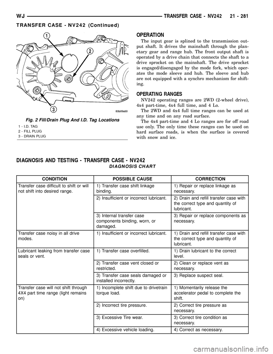
A circular ID tag is attached to the rear case of
each transfer case (Fig. 2). The ID tag provides the
transfer case model number, assembly number, serial
number, and low range ratio.The transfer case serial number also represents
the date of build.
SHIFT MECHANISM
Operating ranges are selected with a lever in the
floor mounted shifter assembly. The shift lever is con-
nected to the transfer case range lever by an adjust-
able cable. A straight line shift pattern is used.
Range positions are marked on the shifter bezel.
Fig. 1 NV242 Transfer Case
21 - 280 TRANSFER CASE - NV242WJ
Page 1800 of 2199

OPERATION
The input gear is splined to the transmission out-
put shaft. It drives the mainshaft through the plan-
etary gear and range hub. The front output shaft is
operated by a drive chain that connects the shaft to a
drive sprocket on the mainshaft. The drive sprocket
is engaged/disengaged by the mode fork, which oper-
ates the mode sleeve and hub. The sleeve and hub
are not equipped with a synchro mechanism for shift-
ing.
OPERATING RANGES
NV242 operating ranges are 2WD (2-wheel drive),
4x4 part-time, 4x4 full time, and 4 Lo.
The 2WD and 4x4 full time ranges can be used at
any time and on any road surface.
The 4x4 part-time and 4 Lo ranges are for off road
use only. The only time these ranges can be used on
hard surface roads, is when the surface is covered
with snow and ice.
DIAGNOSIS AND TESTING - TRANSFER CASE - NV242
DIAGNOSIS CHART
CONDITION POSSIBLE CAUSE CORRECTION
Transfer case difficult to shift or will
not shift into desired range.1) Transfer case shift linkage
binding.1) Repair or replace linkage as
necessary.
2) Insufficient or incorrect lubricant. 2) Drain and refill transfer case with
the correct type and quantity of
lubricant.
3) Internal transfer case
components binding, worn, or
damaged.3) Repair or replace components as
necessary.
Transfer case noisy in all drive
modes.1) Insufficient or incorrect lubricant. 1) Drain and refill transfer case with
the correct type and quantity of
lubricant.
Lubricant leaking from transfer case
seals or vent.1) Transfer case overfilled. 1) Drain lubricant to the correct
level.
2) Transfer case vent closed or
restricted.2) Clean or replace vent as
necessary.
3) Transfer case seals damaged or
installed incorrectly.3) Replace suspect seal.
Transfer case will not shift through
4X4 part time range (light remains
on)1) Incomplete shift due to drivetrain
torque load.1) Momentarily release the
accelerator pedal to complete the
shift.
2) Incorrect tire pressure. 2) Correct tire pressure as
necessary.
3) Excessive Tire wear. 3) Correct tire condition as
necessary.
4) Excessive vehicle loading. 4) Correct as necessary.
Fig. 2 Fill/Drain Plug And I.D. Tag Locations
1 - I.D. TAG
2 - FILL PLUG
3 - DRAIN PLUG
WJTRANSFER CASE - NV242 21 - 281
TRANSFER CASE - NV242 (Continued)
Page 1801 of 2199

REMOVAL
(1) Shift transfer case into NEUTRAL.
(2) Raise vehicle.
(3) Remove transfer case drain plug and drain
transfer case lubricant.
(4) Mark front and rear propeller shaft yokes for
alignment reference.
(5) Support transmission with jack stand.
(6) Remove rear crossmember and skid plate, if
equipped (Fig. 3).
(7) Disconnect front/rear propeller shafts at trans-
fer case. (Refer to 3 - DIFFERENTIAL & DRIV-
ELINE/PROPELLER SHAFT/PROPELLER SHAFT -
REMOVAL)
(8) Disconnect transfer case cable from range
lever.
(9) Disconnect transfer case vent hose (Fig. 4) and
transfer case position sensor.
(10) Support transfer case with transmission jack.
(11) Secure transfer case to jack with chains.
(12) Remove nuts attaching transfer case to trans-
mission.(13) Pull transfer case and jack rearward to disen-
gage transfer case.
(14) Remove transfer case from under vehicle.
DISASSEMBLY
REAR RETAINER - NV242LD
(1) Remove output shaft boot. Spread band clamp
that secures boot on slinger with a suitable awl.
Then slide boot off shaft (Fig. 5).
Fig. 3 Crossmember Removal
1 - CROSSMEMBER
2 - REAR TRANSMISSION MOUNT
Fig. 4 Transfer Case Mounting
1 - NV242 TRANSFER CASE
Fig. 5 Output Boot - Typical
1 - SLINGER
2 - BOOT
3-AWL
4 - TRANSFER CASE
21 - 282 TRANSFER CASE - NV242WJ
TRANSFER CASE - NV242 (Continued)
Page 1802 of 2199
(2) Using puller MD-998056-A, remove rear slinger
(Fig. 6).
(3) Remove rear seal from retainer (Fig. 7). Use
pry tool, or collapse seal with punch to remove it.(4) Remove rear output bearing I.D. retaining ring
(Fig. 8).
(5) Remove rear retainer bolts.
(6) Remove rear retainer. Tap retainer with mallet
and pry upward to break sealer bead. Then slide
retainer off case and output shaft (Fig. 9).
Fig. 6 Rear Slinger Removal
1 - TRANSFER CASE
2 - SPECIAL TOOL MD998056-A
3 - SLINGER
Fig. 7 Rear Retainer Seal
1 - REAR RETAINER
2 - OUTPUT SHAFT SEAL
Fig. 8 Output Shaft Rear Bearing Retaining Ring
1 - SNAP-RING PLIERS
2 - RETAINING RING
Fig. 9 Rear Retainer Removal
1 - MAINSHAFT
2 - REAR RETAINER
WJTRANSFER CASE - NV242 21 - 283
TRANSFER CASE - NV242 (Continued)
Page 1803 of 2199

REAR RETAINER - NV242HD
(1) Remove extension housing bolts.
(2) Tap extension housing with plastic or rawhide
mallet to loosen sealer (Fig. 10).
(3) Separate extension housing from rear retainer.
(4) Remove rear bearing snap-ring (Fig. 11).
(5) Remove bolts holding rear retainer to rear case
half.
(6) Loosen rear retainer with pry tool to break
sealer bead. Pry only against retainer boss as shown
(Fig. 12).
(7) Slide retainer off case and output shaft (Fig.
13).
OIL PUMP AND REAR CASE HALF
(1) Remove rear bearing O.D. retaining ring with
snap ring pliers. Then tilt pump and slide it off out-
put shaft (Fig. 14)
(2) Remove pickup tube O-ring from pump (Fig.
15) but do not disassemble pump; it is not a repair-
able part.
(3) Remove seal from oil pump with pry tool.
(4) Remove bolts attaching rear case to front case
(Fig. 16). Note position of the two black finish bolts
at each end of the case. These bolts go through the
case dowels and require a washer under the bolt
head.
Fig. 10 Remove Extension Housing
1 - EXTENSION HOUSING
2 - PLASTIC HAMMER
3 - REAR RETAINER
Fig. 11 Remove the Output Bearing Snap-ring
1 - REAR RETAINER
2 - SNAP-RING
3 - REAR BEARING
Fig. 12 Loosening Rear Retainer
1 - REAR RETAINER
2-TAB(2)
3 - SCREWDRIVER
4-TAB
Fig. 13 Rear Retainer Removal
1 - MAINSHAFT
2 - REAR RETAINER
21 - 284 TRANSFER CASE - NV242WJ
TRANSFER CASE - NV242 (Continued)
Page 1804 of 2199
(5) Remove rear case from front case (Fig. 17).
Insert screwdrivers into slots cast into each end of
case. Then pry upward to break sealer bead and
remove rear case.
CAUTION: Do not pry on the sealing surface of
either case half as the surfaces will become dam-
aged.
(6) Remove oil pickup tube and screen from rear
case (Fig. 18).
Fig. 14 Oil Pump Removal
1 - OIL PUMP
Fig. 15 Pickup Tube O-Ring Location
1 - OIL PUMP
2 - O-RING
Fig. 16 Spline And Dowel Bolt Locations
1 - DOWEL BOLT AND WASHER (2)
2 - CASE BOLTS
3 - SPLINE HEAD BOLT (1)
Fig. 17 Loosening/Removing Rear Case
1 - MAINSHAFT
2 - SCREWDRIVER
3 - FRONT CASE
4 - SCREWDRIVER
5 - REAR CASE
Fig. 18 Oil Pickup Screen, Hose And Tube Removal
1 - CONNECTING HOSE
2 - PICKUP SCREEN
3 - PICKUP TUBE
WJTRANSFER CASE - NV242 21 - 285
TRANSFER CASE - NV242 (Continued)
Page 1805 of 2199

COMPANION FLANGE AND RANGE LEVER
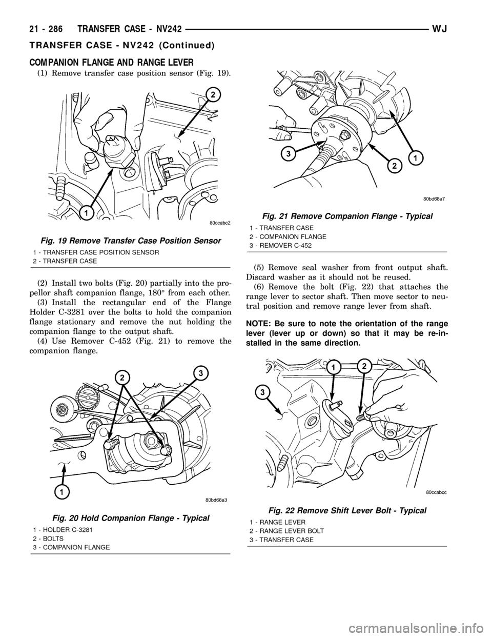
(1) Remove transfer case position sensor (Fig. 19).
(2) Install two bolts (Fig. 20) partially into the pro-
pellor shaft companion flange, 180É from each other.
(3) Install the rectangular end of the Flange
Holder C-3281 over the bolts to hold the companion
flange stationary and remove the nut holding the
companion flange to the output shaft.
(4) Use Remover C-452 (Fig. 21) to remove the
companion flange.(5) Remove seal washer from front output shaft.
Discard washer as it should not be reused.
(6) Remove the bolt (Fig. 22) that attaches the
range lever to sector shaft. Then move sector to neu-
tral position and remove range lever from shaft.
NOTE: Be sure to note the orientation of the range
lever (lever up or down) so that it may be re-in-
stalled in the same direction.
Fig. 19 Remove Transfer Case Position Sensor
1 - TRANSFER CASE POSITION SENSOR
2 - TRANSFER CASE
Fig. 20 Hold Companion Flange - Typical
1 - HOLDER C-3281
2 - BOLTS
3 - COMPANION FLANGE
Fig. 21 Remove Companion Flange - Typical
1 - TRANSFER CASE
2 - COMPANION FLANGE
3 - REMOVER C-452
Fig. 22 Remove Shift Lever Bolt - Typical
1 - RANGE LEVER
2 - RANGE LEVER BOLT
3 - TRANSFER CASE
21 - 286 TRANSFER CASE - NV242WJ
TRANSFER CASE - NV242 (Continued)
Page 1806 of 2199
FRONT OUTPUT SHAFT AND DRIVE CHAIN
(1) Remove drive sprocket snap-ring (Fig. 23).
(2) Remove drive sprocket and chain (Fig. 24).
(3) Remove front output shaft (Fig. 25).
SHIFT FORKS AND MAINSHAFT
(1) Remove shift detent plug, spring and pin (Fig.
26).
Fig. 23 Drive Sprocket Snap-Ring Removal
1 - DRIVE SPROCKET
2 - DRIVE SPROCKET SNAP-RING
Fig. 24 Drive Sprocket And Chain Removal
1 - DRIVE SPROCKET
2 - DRIVE CHAIN
Fig. 25 Removing Front Output Shaft
1 - FRONT OUTPUT SHAFT
Fig. 26 Detent Component Removal
1 - PLUNGER
2 - O-RING
3 - PLUG
4 - SPRING
WJTRANSFER CASE - NV242 21 - 287
TRANSFER CASE - NV242 (Continued)