Page 1185 of 2199

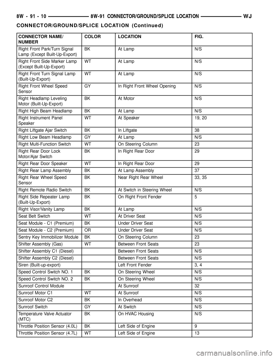
CONNECTOR NAME/
NUMBERCOLOR LOCATION FIG.
Right Front Park/Turn Signal
Lamp (Except Built-Up-Export)BK At Lamp N/S
Right Front Side Marker Lamp
(Except Built-Up-Export)WT At Lamp N/S
Right Front Turn Signal Lamp
(Built-Up-Export)WT At Lamp N/S
Right Front Wheel Speed
SensorGY In Right Front Wheel Opening N/S
Right Headlamp Leveling
Motor (Built-Up-Export)BK At Motor N/S
Right High Beam Headlamp BK At Lamp N/S
Right Instrument Panel
SpeakerWT At Speaker 19, 20
Right Liftgate Ajar Switch BK In Liftgate 38
Right Low Beam Headlamp GY At Lamp N/S
Right Multi-Function Switch WT On Steering Column 23
Right Rear Door Lock
Motor/Ajar SwitchBK In Right Rear Door 29
Right Rear Door Speaker WT In Right Rear Door 29
Right Rear Lamp Assembly BK At Lamp Assembly 37
Right Rear Wheel Speed
SensorBK Near Right Rear Wheel 33, 35
Right Remote Radio Switch BK At Switch in Steering Wheel N/S
Right Side Repeater Lamp
(Built-Up-Export)BK On Right Front Fender 5
Right Visor/Vanity Lamp BK At Lamp N/S
Seat Belt Switch WT At Driver Seat N/S
Seat Module - C1 (Premium) BK Under Driver Seat N/S
Seat Module - C2 (Premium) OR Under Driver Seat N/S
Sentry Key Immobilizer Module BK On Steering Column 23
Shifter Assembly (Gas) WT Between Front Seats 23
Shifter Assembly C1 (Diesel) Between Front Seats N/S
Shifter Assembly C2 (Diesel) Between Front Seats N/S
Siren (Built-up-export) Left Front Fender 3, 4
Speed Control Switch NO. 1 BK On Steering Wheel N/S
Speed Control Switch NO. 2 BK On Steering Wheel N/S
Sunroof Control Module At Sunroof 32
Sunroof Motor C1 WT At Sunroof N/S
Sunroof Motor C2 BK In Overhead N/S
Sunroof Switch GY At Switch N/S
Temperature Valve Actuator
(MTC)BK On HVAC Housing N/S
Throttle Position Sensor (4.0L) BK Left Side of Engine 9
Throttle Position Sensor (4.7L) WT Left Side of Engine 13
8W - 91 - 10 8W-91 CONNECTOR/GROUND/SPLICE LOCATIONWJ
CONNECTOR/GROUND/SPLICE LOCATION (Continued)
Page 1191 of 2199

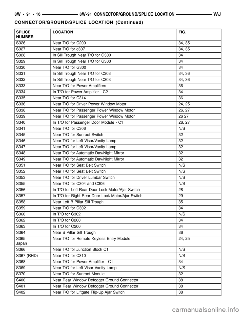
SPLICE
NUMBERLOCATION FIG.
S326 Near T/O for C200 34, 35
S327 Near T/O for c307 34, 35
S328 In Sill Trough Near T/O for G300 34
S329 In Sill Trough Near T/O for G300 34
S330 Near T/O for G300 34
S331 In Sill Trough Near T/O for C303 34, 36
S332 In Sill Trough Near T/O for C303 34, 36
S333 Near T/O for Power Amplifiers 36
S334 In T/O for Power Amplifier - C2 34
S335 Near T/O for C314 36
S336 Near T/O for Driver Power Window Motor 24, 25
S338 Near T/O for Passenger Power Window Motor 26, 27
S339 Near T/O for Passenger Power Window Motor 26 27
S340 In T/O for Passenger Door Module - C1 26, 27
S341 Near T/O for C306 N/S
S345 Near T/O for Sunroof Switch 32
S346 Near T/O for Left Visor/Vanity Lamp 32
S347 Near T/O for Left Visor/Vanity Lamp 32
S348 Near T/O for Automatic Day/Night Mirror 32
S349 Near T/O for Automatic Day/Night Mirror 32
S351 Near T/O for Seat Belt Switch N/S
S352 Near T/O for Seat Belt Switch N/S
S353 Near T/O for Driver Lumbar Switch N/S
S355 Near T/O for C304 and C306 N/S
S356 In T/O for Left Rear Door Lock Motor/Ajar Switch 28
S357 In T/O for Right Rear Door Lock Motor/Ajar Switch 29
S358 Near Left B Pillar Sill Trough 35
S359 Near T/O for C302 34
S360 In T/O for C302 N/S
S362 In T/O for C200 34
S363 In T/O for C200 34
S364 Near B Pillar Sill Trough 36
S365
JapanNear T/O for Remote Keyless Entry Module 24, 25
S366 Near T/O for Junction Block C1 N/S
S367 (RHD) Near T/O for C310 N/S
S368 Near T/O for Power Amplifier - C1 34
S369 Near T/O for Left Visor Vanity Lamp N/S
S370 Near T/O for Sunroof Module 32
S400 Near Rear Window Defogger Ground Connector 38
S401 Near Rear Window Defogger Ground Connector 38
S402 Near T/O for Liftgate Flip-Up Ajar Switch 38
8W - 91 - 16 8W-91 CONNECTOR/GROUND/SPLICE LOCATIONWJ
CONNECTOR/GROUND/SPLICE LOCATION (Continued)
Page 1214 of 2199
Fig. 23 STEERING COLUMN
Fig. 24 DRIVER DOOR LHD
WJ8W-91 CONNECTOR/GROUND/SPLICE LOCATION 8W - 91 - 39
CONNECTOR/GROUND/SPLICE LOCATION (Continued)
Page 1215 of 2199
Fig. 25 DRIVER DOOR RHD
Fig. 26 PASSENGER DOOR LHD
8W - 91 - 40 8W-91 CONNECTOR/GROUND/SPLICE LOCATIONWJ
CONNECTOR/GROUND/SPLICE LOCATION (Continued)
Page 1216 of 2199
Fig. 27 PASSENGER DOOR RHD
Fig. 28 LEFT REAR DOOR
WJ8W-91 CONNECTOR/GROUND/SPLICE LOCATION 8W - 91 - 41
CONNECTOR/GROUND/SPLICE LOCATION (Continued)
Page 1217 of 2199
Fig. 29 RIGHT REAR DOOR
Fig. 30 KICK PANEL AREA LHD
8W - 91 - 42 8W-91 CONNECTOR/GROUND/SPLICE LOCATIONWJ
CONNECTOR/GROUND/SPLICE LOCATION (Continued)
Page 1226 of 2199

8W-97 POWER DISTRIBUTION
TABLE OF CONTENTS
page page
POWER DISTRIBUTION
DESCRIPTION..........................1
OPERATION............................1
SPECIAL TOOLS
POWER DISTRIBUTION SYSTEMS.........2
CIGAR LIGHTER OUTLET
DESCRIPTION..........................2
OPERATION............................2
DIAGNOSIS AND TESTING - CIGAR LIGHTER
OUTLET.............................2
CIGAR LIGHTER OUTLET DOOR SPRING
REMOVAL.............................3
INSTALLATION..........................3
IOD FUSE
DESCRIPTION..........................3
OPERATION............................4
REMOVAL.............................4
INSTALLATION..........................4
JUNCTION BLOCK
DESCRIPTION..........................5
OPERATION............................5
REMOVAL.............................5
INSTALLATION..........................6
POWER DISTRIBUTION CENTER
DESCRIPTION..........................7
OPERATION............................8
REMOVAL.............................8
DISASSEMBLY
POWER DISTRIBUTION CENTER
DISASSEMBLY........................9ASSEMBLY
POWER DISTRIBUTION CENTER
ASSEMBLY..........................11
INSTALLATION.........................12
POWER OUTLET
DESCRIPTION - FRONT POWER OUTLET....12
OPERATION - FRONT POWER OUTLET......12
DIAGNOSIS AND TESTING - POWER OUTLET . 12
REMOVAL.............................13
INSTALLATION.........................13
POWER OUTLET RELAY
DESCRIPTION.........................13
OPERATION...........................14
DIAGNOSIS AND TESTING - POWER OUTLET
RELAY..............................14
REMOVAL.............................15
INSTALLATION.........................15
IOD WIRE HARNESS CONNECTOR
DESCRIPTION.........................15
OPERATION...........................15
FUSE COVER
REMOVAL.............................16
INSTALLATION.........................16
REAR POWER OUTLET
DESCRIPTION - REAR POWER OUTLET.....16
OPERATION - REAR POWER OUTLET.......17
DIAGNOSIS AND TESTING - REAR POWER
OUTLET............................17
REMOVAL.............................17
INSTALLATION.........................18
POWER DISTRIBUTION
DESCRIPTION
This group covers the various standard and
optional power distribution components used on this
model. The power distribution system for this vehicle
consists of the following components:
²Power Distribution Center (PDC)
²Junction Block (JB)
²Power Outlets
The power distribution system also incorporates
various types of circuit control and protection fea-
tures, including:
²Automatic resetting circuit breakers
²Blade-type fuses
²Bus bars
²Cartridge fuses²Circuit splice blocks
²Flashers
²Fusible links
²Standard and Micro-Relays
Following are general descriptions of the major
components in the power distribution system. See the
owner's manual in the vehicle glove box for more
information on the features and use of all of the
power distribution system components. Refer to Wir-
ing Diagrams for complete circuit diagrams.
OPERATION
The power distribution system for this vehicle is
designed to provide safe, reliable, and centralized dis-
tribution points for the electrical current required to
operate all of the standard and optional factory-in-
stalled electrical and electronic powertrain, chassis,
safety, security, comfort and convenience systems. At
WJ8W-97 POWER DISTRIBUTION 8W - 97 - 1
Page 1228 of 2199

the junction block. If OK, go to Step 3. If not OK,
repair the open or short as required.
(3) Remove the cigar lighter knob and element
from the cigar lighter outlet shell. Check for continu-
ity between the inside circumference of the cigar
lighter outlet shell and a good ground. there should
be continuity. If OK, go to Step 4. If not OK, go to
Step 5.
(4) Turn the ignition switch to the On position.
Check for battery voltage at the insulated contact
located at the back of the cigar lighter outlet shell. If
OK, replace the faulty cigar lighter knob and ele-
ment. If not OK, go to Step 5.
(5) Turn the ignition switch to the Off position.
Disconnect and isolate the battery negative cable.
Remove the instrument panel center lower bezel.
Check for continuity between the ground circuit cav-
ity of the cigar lighter wire harness connector and a
good ground. There should be continuity. If OK, go to
Step 6. If not OK, repair the open ground circuit to
ground as required.
(6) Connect the battery negative cable. Turn the
ignition switch to the Accessory or On positions.
Check for battery voltage at the fused B(+) circuit
cavity of the cigar lighter wire harness connector. If
OK, replace the faulty cigar lighter outlet. If not OK,
repair the open fused B(+) circuit to the junction
block fuse as required.
CIGAR LIGHTER OUTLET
DOOR SPRING
REMOVAL
(1) Disconnect and isolate the negative battery
cable.
(2) Remove the instrument panel center lower
bezel from the I.P. Refer to Body for the procedure.
(3) Remove the cigar lighter outlet door spring
from its locating holes (Fig. 1).
INSTALLATION
(1) Install the cigar outlet door spring in its locat-
ing holes.
(2) Install the instrument panel center lower bezel
on the I.P. Refer to Body for the procedure.
(3) Connect the negative battery cable.
IOD FUSE
DESCRIPTION
All vehicles are equipped with an Ignition-Off
Draw (IOD) fuse (Fig. 2) that is removed from its
cavity in the Power Distribution Center (PDC) when
the vehicle is shipped from the factory. Dealer per-sonnel are to remove the IOD fuse from the storage
location and install it into PDC fuse cavity 15 as part
Fig. 1 Cigar Lighter Outlet Door Spring
1 - CIGAR LIGHTER OUTLET
2 - CIGAR LIGHTER OUTLET DOOR SPRING
Fig. 2 Ignition-Off Draw Fuse
1 - POWER DISTRIBUTION CENTER
2 - IGNITION-OFF DRAW FUSE
3 - IOD FUSE STORAGE CAVITY
WJ8W-97 POWER DISTRIBUTION 8W - 97 - 3
CIGAR LIGHTER OUTLET (Continued)