2002 JEEP GRAND CHEROKEE Lamps
[x] Cancel search: LampsPage 1446 of 2199
INLET FILTER
REMOVAL
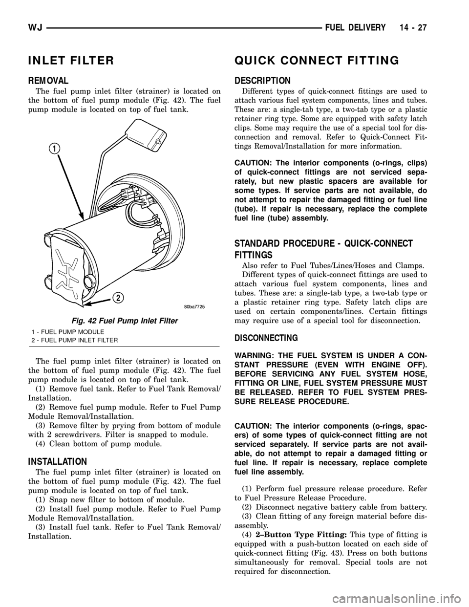
The fuel pump inlet filter (strainer) is located on
the bottom of fuel pump module (Fig. 42). The fuel
pump module is located on top of fuel tank.
The fuel pump inlet filter (strainer) is located on
the bottom of fuel pump module (Fig. 42). The fuel
pump module is located on top of fuel tank.
(1) Remove fuel tank. Refer to Fuel Tank Removal/
Installation.
(2) Remove fuel pump module. Refer to Fuel Pump
Module Removal/Installation.
(3) Remove filter by prying from bottom of module
with 2 screwdrivers. Filter is snapped to module.
(4) Clean bottom of pump module.
INSTALLATION
The fuel pump inlet filter (strainer) is located on
the bottom of fuel pump module (Fig. 42). The fuel
pump module is located on top of fuel tank.
(1) Snap new filter to bottom of module.
(2) Install fuel pump module. Refer to Fuel Pump
Module Removal/Installation.
(3) Install fuel tank. Refer to Fuel Tank Removal/
Installation.
QUICK CONNECT FITTING
DESCRIPTION
Different types of quick-connect fittings are used to
attach various fuel system components, lines and tubes.
These are: a single-tab type, a two-tab type or a plastic
retainer ring type. Some are equipped with safety latch
clips. Some may require the use of a special tool for dis-
connection and removal. Refer to Quick-Connect Fit-
tings Removal/Installation for more information.
CAUTION: The interior components (o-rings, clips)
of quick-connect fittings are not serviced sepa-
rately, but new plastic spacers are available for
some types. If service parts are not available, do
not attempt to repair the damaged fitting or fuel line
(tube). If repair is necessary, replace the complete
fuel line (tube) assembly.
STANDARD PROCEDURE - QUICK-CONNECT
FITTINGS
Also refer to Fuel Tubes/Lines/Hoses and Clamps.
Different types of quick-connect fittings are used to
attach various fuel system components, lines and
tubes. These are: a single-tab type, a two-tab type or
a plastic retainer ring type. Safety latch clips are
used on certain components/lines. Certain fittings
may require use of a special tool for disconnection.
DISCONNECTING
WARNING: THE FUEL SYSTEM IS UNDER A CON-
STANT PRESSURE (EVEN WITH ENGINE OFF).
BEFORE SERVICING ANY FUEL SYSTEM HOSE,
FITTING OR LINE, FUEL SYSTEM PRESSURE MUST
BE RELEASED. REFER TO FUEL SYSTEM PRES-
SURE RELEASE PROCEDURE.
CAUTION: The interior components (o-rings, spac-
ers) of some types of quick-connect fitting are not
serviced separately. If service parts are not avail-
able, do not attempt to repair a damaged fitting or
fuel line. If repair is necessary, replace complete
fuel line assembly.
(1) Perform fuel pressure release procedure. Refer
to Fuel Pressure Release Procedure.
(2) Disconnect negative battery cable from battery.
(3) Clean fitting of any foreign material before dis-
assembly.
(4)2±Button Type Fitting:This type of fitting is
equipped with a push-button located on each side of
quick-connect fitting (Fig. 43). Press on both buttons
simultaneously for removal. Special tools are not
required for disconnection.
Fig. 42 Fuel Pump Inlet Filter
1 - FUEL PUMP MODULE
2 - FUEL PUMP INLET FILTER
WJFUEL DELIVERY 14 - 27
Page 1458 of 2199
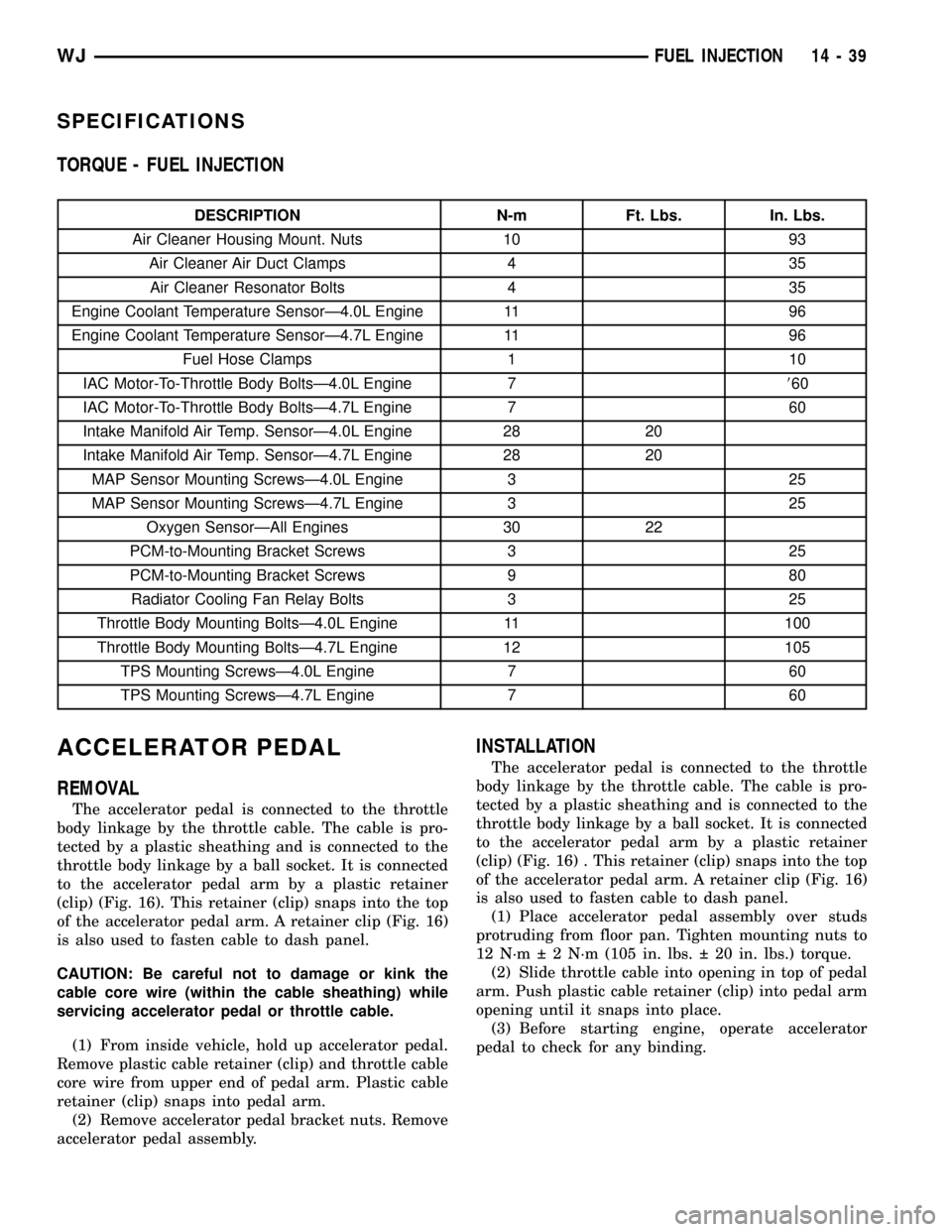
SPECIFICATIONS
TORQUE - FUEL INJECTION
DESCRIPTION N-m Ft. Lbs. In. Lbs.
Air Cleaner Housing Mount. Nuts 10 93
Air Cleaner Air Duct Clamps 4 35
Air Cleaner Resonator Bolts 4 35
Engine Coolant Temperature SensorÐ4.0L Engine 11 96
Engine Coolant Temperature SensorÐ4.7L Engine 11 96
Fuel Hose Clamps 1 10
IAC Motor-To-Throttle Body BoltsÐ4.0L Engine 7860
IAC Motor-To-Throttle Body BoltsÐ4.7L Engine 7 60
Intake Manifold Air Temp. SensorÐ4.0L Engine 28 20
Intake Manifold Air Temp. SensorÐ4.7L Engine 28 20
MAP Sensor Mounting ScrewsÐ4.0L Engine 3 25
MAP Sensor Mounting ScrewsÐ4.7L Engine 3 25
Oxygen SensorÐAll Engines 30 22
PCM-to-Mounting Bracket Screws 3 25
PCM-to-Mounting Bracket Screws 9 80
Radiator Cooling Fan Relay Bolts 3 25
Throttle Body Mounting BoltsÐ4.0L Engine 11 100
Throttle Body Mounting BoltsÐ4.7L Engine 12 105
TPS Mounting ScrewsÐ4.0L Engine 7 60
TPS Mounting ScrewsÐ4.7L Engine 7 60
ACCELERATOR PEDAL
REMOVAL
The accelerator pedal is connected to the throttle
body linkage by the throttle cable. The cable is pro-
tected by a plastic sheathing and is connected to the
throttle body linkage by a ball socket. It is connected
to the accelerator pedal arm by a plastic retainer
(clip) (Fig. 16). This retainer (clip) snaps into the top
of the accelerator pedal arm. A retainer clip (Fig. 16)
is also used to fasten cable to dash panel.
CAUTION: Be careful not to damage or kink the
cable core wire (within the cable sheathing) while
servicing accelerator pedal or throttle cable.
(1) From inside vehicle, hold up accelerator pedal.
Remove plastic cable retainer (clip) and throttle cable
core wire from upper end of pedal arm. Plastic cable
retainer (clip) snaps into pedal arm.
(2) Remove accelerator pedal bracket nuts. Remove
accelerator pedal assembly.
INSTALLATION
The accelerator pedal is connected to the throttle
body linkage by the throttle cable. The cable is pro-
tected by a plastic sheathing and is connected to the
throttle body linkage by a ball socket. It is connected
to the accelerator pedal arm by a plastic retainer
(clip) (Fig. 16) . This retainer (clip) snaps into the top
of the accelerator pedal arm. A retainer clip (Fig. 16)
is also used to fasten cable to dash panel.
(1) Place accelerator pedal assembly over studs
protruding from floor pan. Tighten mounting nuts to
12 N´m 2 N´m (105 in. lbs. 20 in. lbs.) torque.
(2) Slide throttle cable into opening in top of pedal
arm. Push plastic cable retainer (clip) into pedal arm
opening until it snaps into place.
(3) Before starting engine, operate accelerator
pedal to check for any binding.
WJFUEL INJECTION 14 - 39
Page 1515 of 2199
HOSES - 4.7L
DESCRIPTION
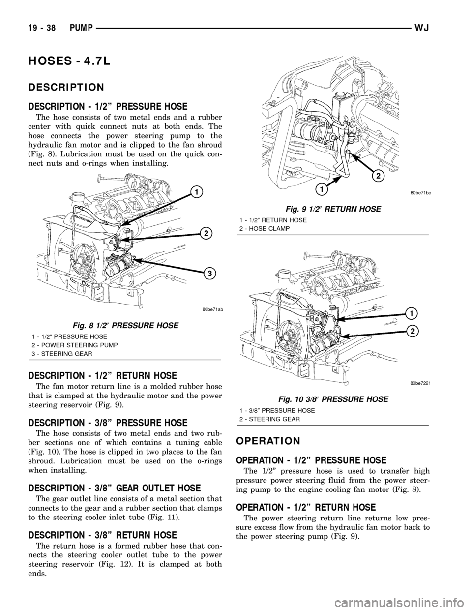
DESCRIPTION - 1/2º PRESSURE HOSE
The hose consists of two metal ends and a rubber
center with quick connect nuts at both ends. The
hose connects the power steering pump to the
hydraulic fan motor and is clipped to the fan shroud
(Fig. 8). Lubrication must be used on the quick con-
nect nuts and o-rings when installing.
DESCRIPTION - 1/2º RETURN HOSE
The fan motor return line is a molded rubber hose
that is clamped at the hydraulic motor and the power
steering reservoir (Fig. 9).
DESCRIPTION - 3/8º PRESSURE HOSE
The hose consists of two metal ends and two rub-
ber sections one of which contains a tuning cable
(Fig. 10). The hose is clipped in two places to the fan
shroud. Lubrication must be used on the o-rings
when installing.
DESCRIPTION - 3/8º GEAR OUTLET HOSE
The gear outlet line consists of a metal section that
connects to the gear and a rubber section that clamps
to the steering cooler inlet tube (Fig. 11).
DESCRIPTION - 3/8º RETURN HOSE
The return hose is a formed rubber hose that con-
nects the steering cooler outlet tube to the power
steering reservoir (Fig. 12). It is clamped at both
ends.
OPERATION
OPERATION - 1/2º PRESSURE HOSE
The 1/2º pressure hose is used to transfer high
pressure power steering fluid from the power steer-
ing pump to the engine cooling fan motor (Fig. 8).
OPERATION - 1/2º RETURN HOSE
The power steering return line returns low pres-
sure excess flow from the hydraulic fan motor back to
the power steering pump (Fig. 9).
Fig. 8 1/2(PRESSURE HOSE
1 - 1/29PRESSURE HOSE
2 - POWER STEERING PUMP
3 - STEERING GEAR
Fig. 9 1/2(RETURN HOSE
1 - 1/29RETURN HOSE
2 - HOSE CLAMP
Fig. 10 3/8(PRESSURE HOSE
1 - 3/89PRESSURE HOSE
2 - STEERING GEAR
19 - 38 PUMPWJ
Page 1789 of 2199
(8) Install the transmission in the vehicle.
(9) Fill the transmission with the recommended
fluid.
TRANSMISSION CONTROL
RELAY
DESCRIPTION
The relay is supplied fused B+ voltage, energized
by the TCM, and is used to supply power to the sole-
noid pack when the transmission is in normal oper-
ating mode.
OPERATION
When the relay is ªoffº, no power is supplied to the
solenoid pack and the transmission is in ªlimp-inº
mode. After a controller reset, the TCM energizes the
relay. Prior to this, the TCM verifies that the con-
tacts are open by checking for no voltage at the
switched battery terminals. After this is verified, the
voltage at the solenoid pack pressure switches is
checked. After the relay is energized, the TCM mon-
itors the terminals to verify that the voltage is
greater than 3 volts.
TRANSMISSION RANGE
SENSOR
DESCRIPTION
The Transmission Range Sensor (TRS) is part of
the solenoid module, which is mounted to the top of
the valve body inside the transmission.
The Transmission Range Sensor (TRS) has five
switch contact pins that:
²Determine shift lever position
²Supply ground to the Starter Relay in Park and
Neutral only.
²Supply +12 V to the backup lamps in Reverse
only.
The TRS also has an integrated temperature sen-
sor (thermistor) that communicates transmission
temperature to the TCM and PCM.
OPERATION
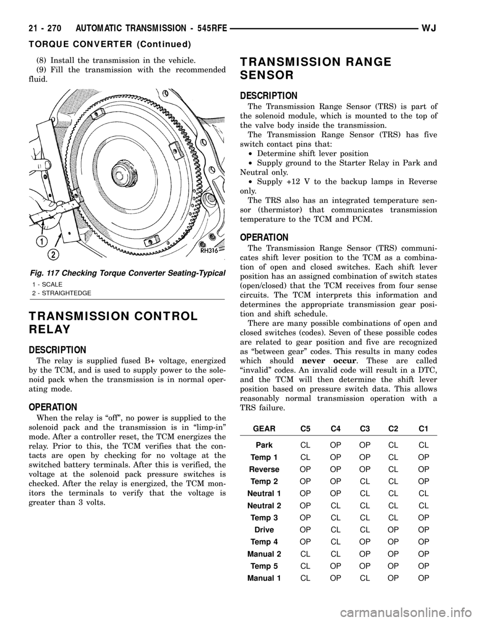
The Transmission Range Sensor (TRS) communi-
cates shift lever position to the TCM as a combina-
tion of open and closed switches. Each shift lever
position has an assigned combination of switch states
(open/closed) that the TCM receives from four sense
circuits. The TCM interprets this information and
determines the appropriate transmission gear posi-
tion and shift schedule.
There are many possible combinations of open and
closed switches (codes). Seven of these possible codes
are related to gear position and five are recognized
as ªbetween gearº codes. This results in many codes
which shouldnever occur. These are called
ªinvalidº codes. An invalid code will result in a DTC,
and the TCM will then determine the shift lever
position based on pressure switch data. This allows
reasonably normal transmission operation with a
TRS failure.
GEAR C5 C4 C3 C2 C1
ParkCL OP OP CL CL
Temp 1CL OP OP CL OP
ReverseOP OP OP CL OP
Temp 2OP OP CL CL OP
Neutral 1OP OP CL CL CL
Neutral 2OP CL CL CL CL
Temp 3OP CL CL CL OP
DriveOP CL CL OP OP
Temp 4OP CL OP OP OP
Manual 2CL CL OP OP OP
Temp 5CL OP OP OP OP
Manual 1CL OP CL OP OP
Fig. 117 Checking Torque Converter Seating-Typical
1 - SCALE
2 - STRAIGHTEDGE
21 - 270 AUTOMATIC TRANSMISSION - 545RFEWJ
TORQUE CONVERTER (Continued)
Page 1813 of 2199
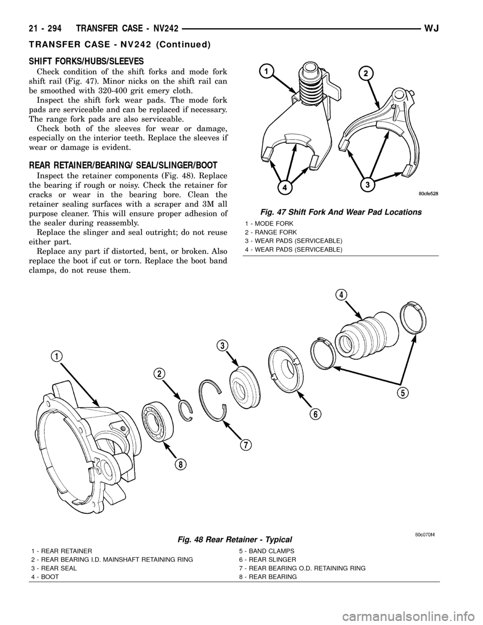
SHIFT FORKS/HUBS/SLEEVES
Check condition of the shift forks and mode fork
shift rail (Fig. 47). Minor nicks on the shift rail can
be smoothed with 320-400 grit emery cloth.
Inspect the shift fork wear pads. The mode fork
pads are serviceable and can be replaced if necessary.
The range fork pads are also serviceable.
Check both of the sleeves for wear or damage,
especially on the interior teeth. Replace the sleeves if
wear or damage is evident.
REAR RETAINER/BEARING/ SEAL/SLINGER/BOOT
Inspect the retainer components (Fig. 48). Replace
the bearing if rough or noisy. Check the retainer for
cracks or wear in the bearing bore. Clean the
retainer sealing surfaces with a scraper and 3M all
purpose cleaner. This will ensure proper adhesion of
the sealer during reassembly.
Replace the slinger and seal outright; do not reuse
either part.
Replace any part if distorted, bent, or broken. Also
replace the boot if cut or torn. Replace the boot band
clamps, do not reuse them.
Fig. 48 Rear Retainer - Typical
1 - REAR RETAINER 5 - BAND CLAMPS
2 - REAR BEARING I.D. MAINSHAFT RETAINING RING 6 - REAR SLINGER
3 - REAR SEAL 7 - REAR BEARING O.D. RETAINING RING
4 - BOOT 8 - REAR BEARING
Fig. 47 Shift Fork And Wear Pad Locations
1 - MODE FORK
2 - RANGE FORK
3 - WEAR PADS (SERVICEABLE)
4 - WEAR PADS (SERVICEABLE)
21 - 294 TRANSFER CASE - NV242WJ
TRANSFER CASE - NV242 (Continued)
Page 1880 of 2199
(4) Close flip up glass panel and verify proper
operation.
(5)
Install liftgate trim panel, refer to (Refer to 23 -
BODY/DECKLID/HATCH/LIFTGATE/TAILGATE/TRIM
PANEL - INSTALLATION).
FLIP-UP GLASS LATCH
STRIKER
REMOVAL
(1) Raise flip up glass panel.
(2) Mark the position of the handle/striker on the
glass panel.
(3) Remove the screws attaching the handle/striker
to the glass.
INSTALLATION
(1) Position the handle/striker on the glass panel
and align the reference marks.
(2) Install the screws attaching the handle/striker
to the glass panel. Tighten the fasteners to 6 N´m (60
in. lbs.).
FLIP-UP GLASS SWITCH
REMOVAL
(1) Remove license plate lamp housing/trim panel
from liftgate, refer to (Refer to 8 - ELECTRICAL/
LAMPS/LIGHTING - EXTERIOR/LICENSE PLATE
LAMP UNIT - REMOVAL).
(2) Squeeze the locking tabs inward to release the
switch from the housing.
(3) Disconnect the switch harness connector,
remove the switch from the housing.
INSTALLATION
(1) Install switch harness connector.(2) Position switch in housing, snap switch into
place.
(3) Install license plate lamp housing/trim panel
onto liftgate, refer to (Refer to 8 - ELECTRICAL/
LAMPS/LIGHTING - EXTERIOR/LICENSE PLATE
LAMP UNIT - INSTALLATION).
HINGE
REMOVAL
NOTE: It is not necessary to remove the liftgate to
replace one or both hinges. The hinges can be
replaced one at a time.
(1) Open the liftgate. Support the liftgate for ease
of repair.
(2) Remove the liftgate header trim panel.
(3) Mark the hinge location with a grease pencil or
other suitable device.
(4) Remove the hinge screws (Fig. 5).
(5) Remove hinge.
INSTALLATION
NOTE: It is not necessary to remove the liftgate to
replace one or both hinges. The hinges can be
replaced one at a time.
(1) Position the hinge on the roof panel and on the
liftgate. (Use 3MŸ Fast and Firm or equivalent on
the hinge to body mating surfaces as a sealant.
(2) Install and tighten hinge screws at roof panel
to 28N´m (21 ft. lbs.).
(3) Install hinge screws at liftgate. Tighten screws
to 28N´m (21 ft. lbs.).
(4) Install liftgate header trim panel.
(5) Check the liftgate for proper alignment and
operation.
WJDECKLID/HATCH/LIFTGATE/TAILGATE 23 - 7
FLIP-UP GLASS LATCH (Continued)
Page 1881 of 2199
LATCH
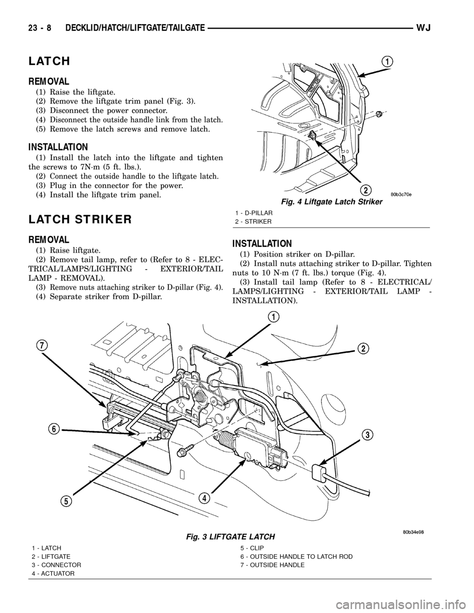
REMOVAL
(1) Raise the liftgate.
(2) Remove the liftgate trim panel (Fig. 3).
(3) Disconnect the power connector.
(4)
Disconnect the outside handle link from the latch.
(5) Remove the latch screws and remove latch.
INSTALLATION
(1) Install the latch into the liftgate and tighten
the screws to 7N´m (5 ft. lbs.).
(2)
Connect the outside handle to the liftgate latch.
(3) Plug in the connector for the power.
(4) Install the liftgate trim panel.
LATCH STRIKER
REMOVAL
(1) Raise liftgate.
(2) Remove tail lamp, refer to (Refer to 8 - ELEC-
TRICAL/LAMPS/LIGHTING - EXTERIOR/TAIL
LAMP - REMOVAL).
(3)
Remove nuts attaching striker to D-pillar (Fig. 4).
(4) Separate striker from D-pillar.
INSTALLATION
(1) Position striker on D-pillar.
(2) Install nuts attaching striker to D-pillar. Tighten
nuts to 10 N´m (7 ft. lbs.) torque (Fig. 4).
(3) Install tail lamp (Refer to 8 - ELECTRICAL/
LAMPS/LIGHTING - EXTERIOR/TAIL LAMP -
INSTALLATION).
Fig. 3 LIFTGATE LATCH
1-LATCH
2 - LIFTGATE
3 - CONNECTOR
4 - ACTUATOR5 - CLIP
6 - OUTSIDE HANDLE TO LATCH ROD
7 - OUTSIDE HANDLE
Fig. 4 Liftgate Latch Striker
1 - D-PILLAR
2 - STRIKER
23 - 8 DECKLID/HATCH/LIFTGATE/TAILGATEWJ
Page 1900 of 2199
COWL GRILLE
REMOVAL
(1) Remove wiper arms, refer to (Refer to 8 -
ELECTRICAL/WIPERS/WASHERS/WIPER ARMS -
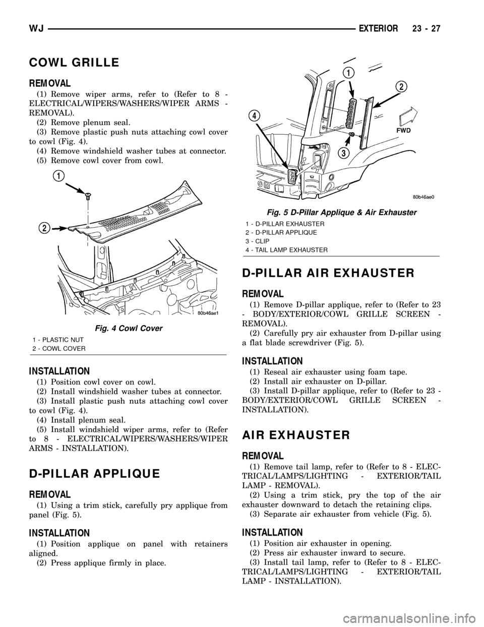
REMOVAL).
(2) Remove plenum seal.
(3) Remove plastic push nuts attaching cowl cover
to cowl (Fig. 4).
(4) Remove windshield washer tubes at connector.
(5) Remove cowl cover from cowl.
INSTALLATION
(1) Position cowl cover on cowl.
(2) Install windshield washer tubes at connector.
(3) Install plastic push nuts attaching cowl cover
to cowl (Fig. 4).
(4) Install plenum seal.
(5) Install windshield wiper arms, refer to (Refer
to 8 - ELECTRICAL/WIPERS/WASHERS/WIPER
ARMS - INSTALLATION).
D-PILLAR APPLIQUE
REMOVAL
(1) Using a trim stick, carefully pry applique from
panel (Fig. 5).
INSTALLATION
(1) Position applique on panel with retainers
aligned.
(2) Press applique firmly in place.
D-PILLAR AIR EXHAUSTER
REMOVAL
(1) Remove D-pillar applique, refer to (Refer to 23
- BODY/EXTERIOR/COWL GRILLE SCREEN -
REMOVAL).
(2) Carefully pry air exhauster from D-pillar using
a flat blade screwdriver (Fig. 5).
INSTALLATION
(1) Reseal air exhauster using foam tape.
(2) Install air exhauster on D-pillar.
(3) Install D-pillar applique, refer to (Refer to 23 -
BODY/EXTERIOR/COWL GRILLE SCREEN -
INSTALLATION).
AIR EXHAUSTER
REMOVAL
(1) Remove tail lamp, refer to (Refer to 8 - ELEC-
TRICAL/LAMPS/LIGHTING - EXTERIOR/TAIL
LAMP - REMOVAL).
(2) Using a trim stick, pry the top of the air
exhauster downward to detach the retaining clips.
(3) Separate air exhauster from vehicle (Fig. 5).
INSTALLATION
(1) Position air exhauster in opening.
(2) Press air exhauster inward to secure.
(3) Install tail lamp, refer to (Refer to 8 - ELEC-
TRICAL/LAMPS/LIGHTING - EXTERIOR/TAIL
LAMP - INSTALLATION).
Fig. 4 Cowl Cover
1 - PLASTIC NUT
2 - COWL COVER
Fig. 5 D-Pillar Applique & Air Exhauster
1 - D-PILLAR EXHAUSTER
2 - D-PILLAR APPLIQUE
3 - CLIP
4 - TAIL LAMP EXHAUSTER
WJEXTERIOR 23 - 27