2002 JEEP GRAND CHEROKEE Electronic Control
[x] Cancel search: Electronic ControlPage 782 of 2199
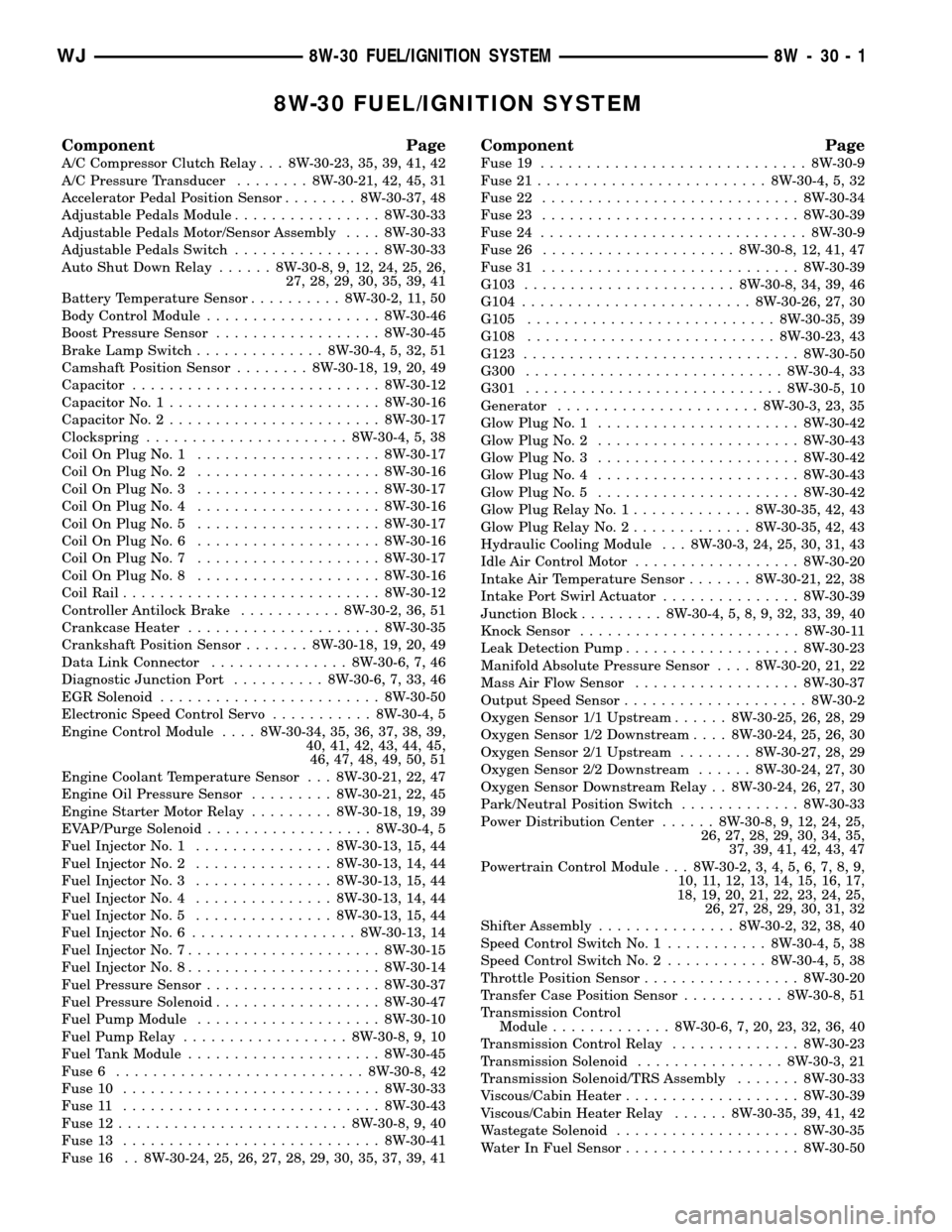
8W-30 FUEL/IGNITION SYSTEM
Component Page
A/C Compressor Clutch Relay . . . 8W-30-23, 35, 39, 41, 42
A/C Pressure Transducer........ 8W-30-21, 42, 45, 31
Accelerator Pedal Position Sensor........ 8W-30-37, 48
Adjustable Pedals Module................ 8W-30-33
Adjustable Pedals Motor/Sensor Assembly.... 8W-30-33
Adjustable Pedals Switch................ 8W-30-33
Auto Shut Down Relay...... 8W-30-8, 9, 12, 24, 25, 26,
27, 28, 29, 30, 35, 39, 41
Battery Temperature Sensor.......... 8W-30-2, 11, 50
Body Control Module................... 8W-30-46
Boost Pressure Sensor.................. 8W-30-45
Brake Lamp Switch.............. 8W-30-4, 5, 32, 51
Camshaft Position Sensor........ 8W-30-18, 19, 20, 49
Capacitor........................... 8W-30-12
Capacitor No. 1....................... 8W-30-16
Capacitor No. 2....................... 8W-30-17
Clockspring...................... 8W-30-4, 5, 38
Coil On Plug No. 1.................... 8W-30-17
Coil On Plug No. 2.................... 8W-30-16
Coil On Plug No. 3.................... 8W-30-17
Coil On Plug No. 4.................... 8W-30-16
Coil On Plug No. 5.................... 8W-30-17
Coil On Plug No. 6.................... 8W-30-16
Coil On Plug No. 7.................... 8W-30-17
Coil On Plug No. 8.................... 8W-30-16
Coil Rail............................ 8W-30-12
Controller Antilock Brake........... 8W-30-2, 36, 51
Crankcase Heater..................... 8W-30-35
Crankshaft Position Sensor....... 8W-30-18, 19, 20, 49
Data Link Connector............... 8W-30-6, 7, 46
Diagnostic Junction Port.......... 8W-30-6, 7, 33, 46
EGR Solenoid........................ 8W-30-50
Electronic Speed Control Servo........... 8W-30-4, 5
Engine Control Module.... 8W-30-34, 35, 36, 37, 38, 39,
40, 41, 42, 43, 44, 45,
46, 47, 48, 49, 50, 51
Engine Coolant Temperature Sensor . . . 8W-30-21, 22, 47
Engine Oil Pressure Sensor......... 8W-30-21, 22, 45
Engine Starter Motor Relay......... 8W-30-18, 19, 39
EVAP/Purge Solenoid.................. 8W-30-4, 5
Fuel Injector No. 1............... 8W-30-13, 15, 44
Fuel Injector No. 2............... 8W-30-13, 14, 44
Fuel Injector No. 3............... 8W-30-13, 15, 44
Fuel Injector No. 4............... 8W-30-13, 14, 44
Fuel Injector No. 5............... 8W-30-13, 15, 44
Fuel Injector No. 6.................. 8W-30-13, 14
Fuel Injector No. 7..................... 8W-30-15
Fuel Injector No. 8..................... 8W-30-14
Fuel Pressure Sensor................... 8W-30-37
Fuel Pressure Solenoid.................. 8W-30-47
Fuel Pump Module.................... 8W-30-10
Fuel Pump Relay.................. 8W-30-8, 9, 10
Fuel Tank Module..................... 8W-30-45
Fuse 6........................... 8W-30-8, 42
Fuse 10............................ 8W-30-33
Fuse 11............................ 8W-30-43
Fuse 12......................... 8W-30-8, 9, 40
Fuse 13............................ 8W-30-41
Fuse 16 . . 8W-30-24, 25, 26, 27, 28, 29, 30, 35, 37, 39, 41
Component Page
Fuse 19............................. 8W-30-9
Fuse 21......................... 8W-30-4, 5, 32
Fuse 22............................ 8W-30-34
Fuse 23............................ 8W-30-39
Fuse 24............................. 8W-30-9
Fuse 26..................... 8W-30-8, 12, 41, 47
Fuse 31............................ 8W-30-39
G103....................... 8W-30-8, 34, 39, 46
G104......................... 8W-30-26, 27, 30
G105........................... 8W-30-35, 39
G108........................... 8W-30-23, 43
G123.............................. 8W-30-50
G300............................ 8W-30-4, 33
G301............................ 8W-30-5, 10
Generator...................... 8W-30-3, 23, 35
Glow Plug No. 1...................... 8W-30-42
Glow Plug No. 2...................... 8W-30-43
Glow Plug No. 3...................... 8W-30-42
Glow Plug No. 4...................... 8W-30-43
Glow Plug No. 5...................... 8W-30-42
Glow Plug Relay No. 1............. 8W-30-35, 42, 43
Glow Plug Relay No. 2............. 8W-30-35, 42, 43
Hydraulic Cooling Module . . . 8W-30-3, 24, 25, 30, 31, 43
Idle Air Control Motor.................. 8W-30-20
Intake Air Temperature Sensor....... 8W-30-21, 22, 38
Intake Port Swirl Actuator............... 8W-30-39
Junction Block......... 8W-30-4, 5, 8, 9, 32, 33, 39, 40
Knock Sensor........................ 8W-30-11
Leak Detection Pump................... 8W-30-23
Manifold Absolute Pressure Sensor.... 8W-30-20, 21, 22
Mass Air Flow Sensor.................. 8W-30-37
Output Speed Sensor.................... 8W-30-2
Oxygen Sensor 1/1 Upstream...... 8W-30-25, 26, 28, 29
Oxygen Sensor 1/2 Downstream.... 8W-30-24, 25, 26, 30
Oxygen Sensor 2/1 Upstream........ 8W-30-27, 28, 29
Oxygen Sensor 2/2 Downstream...... 8W-30-24, 27, 30
Oxygen Sensor Downstream Relay . . 8W-30-24, 26, 27, 30
Park/Neutral Position Switch............. 8W-30-33
Power Distribution Center...... 8W-30-8, 9, 12, 24, 25,
26, 27, 28, 29, 30, 34, 35,
37, 39, 41, 42, 43, 47
Powertrain Control Module . . . 8W-30-2, 3, 4, 5, 6, 7, 8, 9,
10, 11, 12, 13, 14, 15, 16, 17,
18, 19, 20, 21, 22, 23, 24, 25,
26, 27, 28, 29, 30, 31, 32
Shifter Assembly............... 8W-30-2, 32, 38, 40
Speed Control Switch No. 1........... 8W-30-4, 5, 38
Speed Control Switch No. 2........... 8W-30-4, 5, 38
Throttle Position Sensor................. 8W-30-20
Transfer Case Position Sensor........... 8W-30-8, 51
Transmission Control
Module............. 8W-30-6, 7, 20, 23, 32, 36, 40
Transmission Control Relay.............. 8W-30-23
Transmission Solenoid................ 8W-30-3, 21
Transmission Solenoid/TRS Assembly....... 8W-30-33
Viscous/Cabin Heater................... 8W-30-39
Viscous/Cabin Heater Relay...... 8W-30-35, 39, 41, 42
Wastegate Solenoid.................... 8W-30-35
Water In Fuel Sensor................... 8W-30-50
WJ8W-30 FUEL/IGNITION SYSTEM 8W - 30 - 1
Page 852 of 2199

8W-33 VEHICLE SPEED CONTROL
Component Page
Brake Lamp Switch.................. 8W-33-2
Clockspring..................... 8W-33-3, 4, 5
Electronic Speed Control Servo.......... 8W-33-2
Engine Control Module.............. 8W-33-2, 4
Fuse 23............................ 8W-33-2
G108.............................. 8W-33-2
G300.............................. 8W-33-2Component Page
G301.............................. 8W-33-2
Junction Block...................... 8W-33-2
Powertrain Control Module........... 8W-33-2, 3
Shifter Assembly..................... 8W-33-3
Speed Control Switch No. 1............ 8W-33-5
Speed Control Switch No. 2............ 8W-33-5
WJ8W-33 VEHICLE SPEED CONTROL 8W - 33 - 1
Page 1050 of 2199
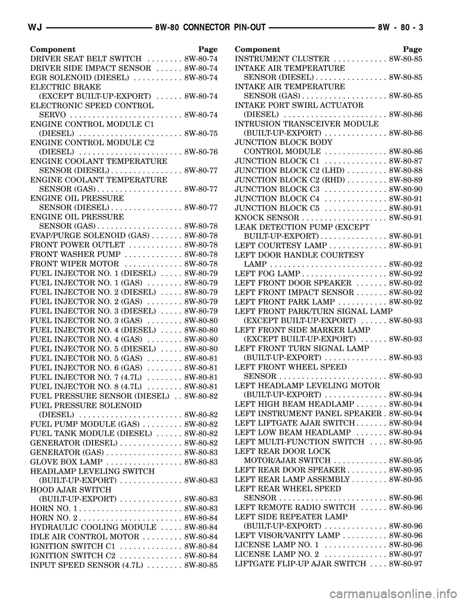
Component Page
DRIVER SEAT BELT SWITCH........ 8W-80-74
DRIVER SIDE IMPACT SENSOR...... 8W-80-74
EGR SOLENOID (DIESEL)........... 8W-80-74
ELECTRIC BRAKE
(EXCEPT BUILT-UP-EXPORT)...... 8W-80-74
ELECTRONIC SPEED CONTROL
SERVO ......................... 8W-80-74
ENGINE CONTROL MODULE C1
(DIESEL)....................... 8W-80-75
ENGINE CONTROL MODULE C2
(DIESEL)....................... 8W-80-76
ENGINE COOLANT TEMPERATURE
SENSOR (DIESEL)................ 8W-80-77
ENGINE COOLANT TEMPERATURE
SENSOR (GAS)................... 8W-80-77
ENGINE OIL PRESSURE
SENSOR (DIESEL)................ 8W-80-77
ENGINE OIL PRESSURE
SENSOR (GAS)................... 8W-80-78
EVAP/PURGE SOLENOID (GAS)....... 8W-80-78
FRONT POWER OUTLET............ 8W-80-78
FRONT WASHER PUMP............. 8W-80-78
FRONT WIPER MOTOR............. 8W-80-78
FUEL INJECTOR NO. 1 (DIESEL)..... 8W-80-79
FUEL INJECTOR NO. 1 (GAS)........ 8W-80-79
FUEL INJECTOR NO. 2 (DIESEL)..... 8W-80-79
FUEL INJECTOR NO. 2 (GAS)........ 8W-80-79
FUEL INJECTOR NO. 3 (DIESEL)..... 8W-80-79
FUEL INJECTOR NO. 3 (GAS)........ 8W-80-80
FUEL INJECTOR NO. 4 (DIESEL)..... 8W-80-80
FUEL INJECTOR NO. 4 (GAS)........ 8W-80-80
FUEL INJECTOR NO. 5 (DIESEL)..... 8W-80-80
FUEL INJECTOR NO. 5 (GAS)........ 8W-80-81
FUEL INJECTOR NO. 6 (GAS)........ 8W-80-81
FUEL INJECTOR NO. 7 (4.7L)........ 8W-80-81
FUEL INJECTOR NO. 8 (4.7L)........ 8W-80-81
FUEL PRESSURE SENSOR (DIESEL) . . 8W-80-82
FUEL PRESSURE SOLENOID
(DIESEL)....................... 8W-80-82
FUEL PUMP MODULE (GAS)......... 8W-80-82
FUEL TANK MODULE (DIESEL)...... 8W-80-82
GENERATOR (DIESEL).............. 8W-80-82
GENERATOR (GAS)................. 8W-80-83
GLOVE BOX LAMP................. 8W-80-83
HEADLAMP LEVELING SWITCH
(BUILT-UP-EXPORT).............. 8W-80-83
HOOD AJAR SWITCH
(BUILT-UP-EXPORT).............. 8W-80-83
HORN NO. 1....................... 8W-80-83
HORN NO. 2....................... 8W-80-84
HYDRAULIC COOLING MODULE..... 8W-80-84
IDLE AIR CONTROL MOTOR......... 8W-80-84
IGNITION SWITCH C1.............. 8W-80-84
IGNITION SWITCH C2.............. 8W-80-84
INPUT SPEED SENSOR (4.7L)........ 8W-80-85Component Page
INSTRUMENT CLUSTER............ 8W-80-85
INTAKE AIR TEMPERATURE
SENSOR (DIESEL)................ 8W-80-85
INTAKE AIR TEMPERATURE
SENSOR (GAS)................... 8W-80-85
INTAKE PORT SWIRL ACTUATOR
(DIESEL)....................... 8W-80-86
INTRUSION TRANSCEIVER MODULE
(BUILT-UP-EXPORT).............. 8W-80-86
JUNCTION BLOCK BODY
CONTROL MODULE.............. 8W-80-86
JUNCTION BLOCK C1.............. 8W-80-87
JUNCTION BLOCK C2 (LHD)......... 8W-80-88
JUNCTION BLOCK C2 (RHD)......... 8W-80-89
JUNCTION BLOCK C3.............. 8W-80-90
JUNCTION BLOCK C4.............. 8W-80-91
JUNCTION BLOCK C5.............. 8W-80-91
KNOCK SENSOR................... 8W-80-91
LEAK DETECTION PUMP (EXCEPT
BUILT-UP-EXPORT)............... 8W-80-91
LEFT COURTESY LAMP............. 8W-80-91
LEFT DOOR HANDLE COURTESY
LAMP.......................... 8W-80-92
LEFT FOG LAMP................... 8W-80-92
LEFT FRONT DOOR SPEAKER....... 8W-80-92
LEFT FRONT IMPACT SENSOR....... 8W-80-92
LEFT FRONT PARK LAMP........... 8W-80-92
LEFT FRONT PARK/TURN SIGNAL LAMP
(EXCEPT BUILT-UP-EXPORT)...... 8W-80-93
LEFT FRONT SIDE MARKER LAMP
(EXCEPT BUILT-UP-EXPORT)...... 8W-80-93
LEFT FRONT TURN SIGNAL LAMP
(BUILT-UP-EXPORT).............. 8W-80-93
LEFT FRONT WHEEL SPEED
SENSOR........................ 8W-80-93
LEFT HEADLAMP LEVELING MOTOR
(BUILT-UP-EXPORT).............. 8W-80-94
LEFT HIGH BEAM HEADLAMP....... 8W-80-94
LEFT INSTRUMENT PANEL SPEAKER . 8W-80-94
LEFT LIFTGATE AJAR SWITCH....... 8W-80-94
LEFT LOW BEAM HEADLAMP....... 8W-80-94
LEFT MULTI-FUNCTION SWITCH.... 8W-80-95
LEFT REAR DOOR LOCK
MOTOR/AJAR SWITCH............ 8W-80-95
LEFT REAR DOOR SPEAKER......... 8W-80-95
LEFT REAR LAMP ASSEMBLY........ 8W-80-95
LEFT REAR WHEEL SPEED
SENSOR........................ 8W-80-96
LEFT REMOTE RADIO SWITCH...... 8W-80-96
LEFT SIDE REPEATER LAMP
(BUILT-UP-EXPORT).............. 8W-80-96
LEFT VISOR/VANITY LAMP.......... 8W-80-96
LICENSE LAMP NO. 1.............. 8W-80-96
LICENSE LAMP NO. 2.............. 8W-80-97
LIFTGATE FLIP-UP AJAR SWITCH.... 8W-80-97
WJ8W-80 CONNECTOR PIN-OUT 8W - 80 - 3
Page 1121 of 2199
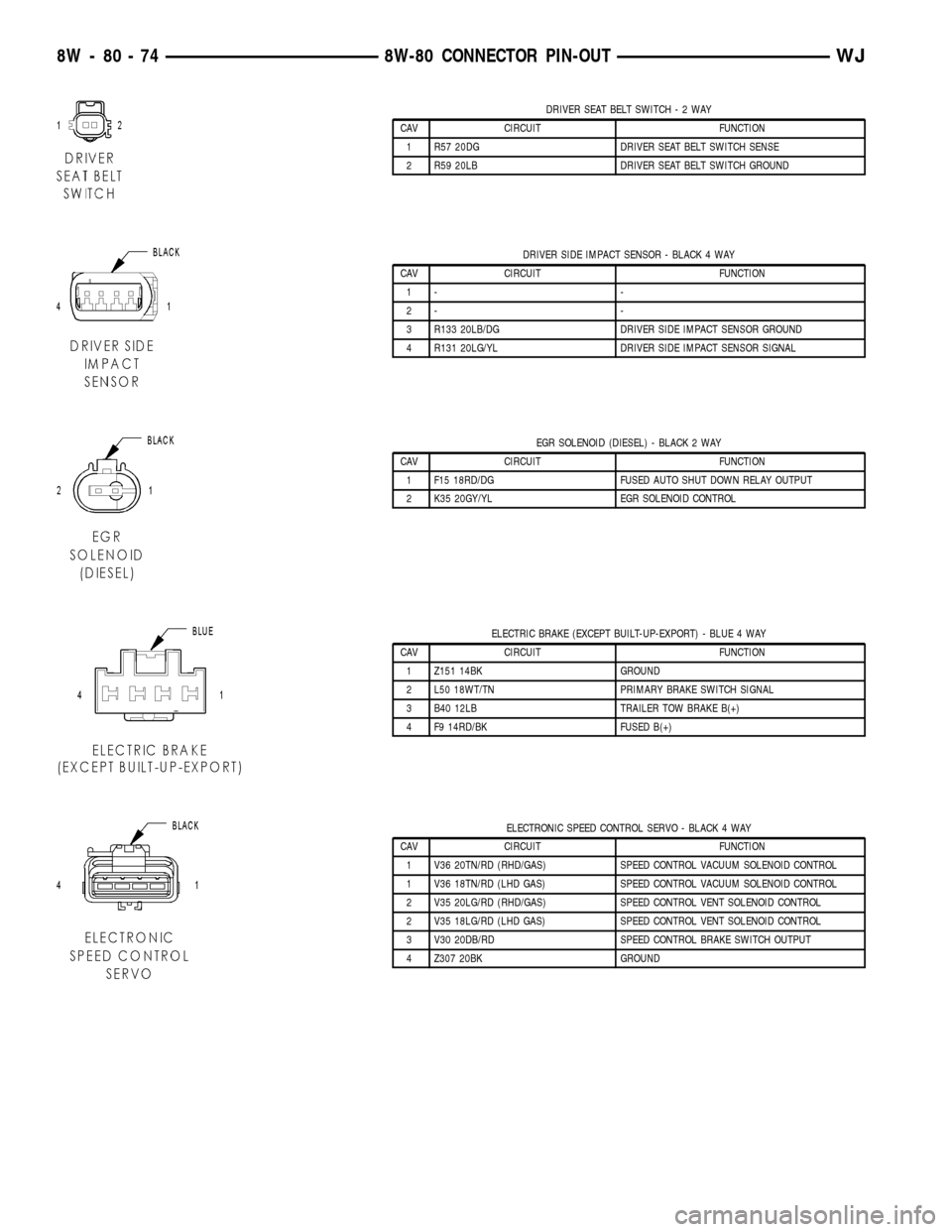
DRIVER SEAT BELT SWITCH-2WAY
CAV CIRCUIT FUNCTION
1 R57 20DG DRIVER SEAT BELT SWITCH SENSE
2 R59 20LB DRIVER SEAT BELT SWITCH GROUND
DRIVER SIDE IMPACT SENSOR - BLACK 4 WAY
CAV CIRCUIT FUNCTION
1- -
2- -
3 R133 20LB/DG DRIVER SIDE IMPACT SENSOR GROUND
4 R131 20LG/YL DRIVER SIDE IMPACT SENSOR SIGNAL
EGR SOLENOID (DIESEL) - BLACK 2 WAY
CAV CIRCUIT FUNCTION
1 F15 18RD/DG FUSED AUTO SHUT DOWN RELAY OUTPUT
2 K35 20GY/YL EGR SOLENOID CONTROL
ELECTRIC BRAKE (EXCEPT BUILT-UP-EXPORT) - BLUE 4 WAY
CAV CIRCUIT FUNCTION
1 Z151 14BK GROUND
2 L50 18WT/TN PRIMARY BRAKE SWITCH SIGNAL
3 B40 12LB TRAILER TOW BRAKE B(+)
4 F9 14RD/BK FUSED B(+)
ELECTRONIC SPEED CONTROL SERVO - BLACK 4 WAY
CAV CIRCUIT FUNCTION
1 V36 20TN/RD (RHD/GAS) SPEED CONTROL VACUUM SOLENOID CONTROL
1 V36 18TN/RD (LHD GAS) SPEED CONTROL VACUUM SOLENOID CONTROL
2 V35 20LG/RD (RHD/GAS) SPEED CONTROL VENT SOLENOID CONTROL
2 V35 18LG/RD (LHD GAS) SPEED CONTROL VENT SOLENOID CONTROL
3 V30 20DB/RD SPEED CONTROL BRAKE SWITCH OUTPUT
4 Z307 20BK GROUND
8W - 80 - 74 8W-80 CONNECTOR PIN-OUTWJ
Page 1180 of 2199
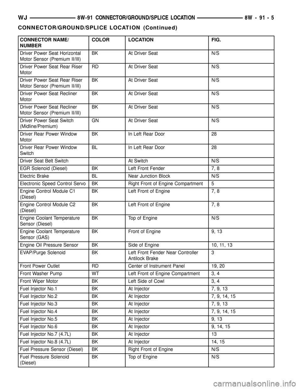
CONNECTOR NAME/
NUMBERCOLOR LOCATION FIG.
Driver Power Seat Horizontal
Motor Sensor (Premium II/III)BK At Driver Seat N/S
Driver Power Seat Rear Riser
MotorRD At Driver Seat N/S
Driver Power Seat Rear Riser
Motor Sensor (Premium II/III)BK At Driver Seat N/S
Driver Power Seat Recliner
MotorBK At Driver Seat N/S
Driver Power Seat Recliner
Motor Sensor (Premium II/III)BK At Driver Seat N/S
Driver Power Seat Switch
(Midline/Premium)GN At Driver Seat N/S
Driver Rear Power Window
MotorBK In Left Rear Door 28
Driver Rear Power Window
SwitchBL In Left Rear Door 28
Driver Seat Belt Switch At Switch N/S
EGR Solenoid (Diesel) BK Left Front Fender 7, 8
Electric Brake BL Near Junction Block N/S
Electronic Speed Control Servo BK Right Front of Engine Compartment 5
Engine Control Module C1
(Diesel)BK Left Front of Engine 7, 8
Engine Control Module C2
(Diesel)BK Left Front of Engine 7, 8
Engine Coolant Temperature
Sensor (Diesel)BK Top of Engine N/S
Engine Coolant Temperature
Sensor (GAS)BK Front of Engine 9, 13
Engine Oil Pressure Sensor BK Side of Engine 10, 11, 13
EVAP/Purge Solenoid BK Left Front Fender Near Controller
Antilock Brake3
Front Power Outlet RD Center of Instrument Panel 19, 20
Front Washer Pump WT Left Front of Engine Compartment 3, 4
Front Wiper Motor BK Left Side of Cowl 3, 4
Fuel Injector No.1 BK At Injector 7, 9, 13
Fuel Injector No.2 BK At Injector 7, 9, 14, 15
Fuel Injector No.3 BK At Injector 7, 9, 13
Fuel Injector No.4 BK At Injector 7, 9, 14, 15
Fuel Injector No.5 BK At Injector 9, 13
Fuel Injector No.6 BK At Injector 9, 14, 15
Fuel Injector No.7 (4.7L) BK At Injector 13
Fuel Injector No.8 (4.7L) BK At Injector 14, 15
Fuel Pressure Sensor (Diesel) BK Right Front of Engine N/S
Fuel Pressure Solenoid
(Diesel)BK Top of Engine N/S
WJ8W-91 CONNECTOR/GROUND/SPLICE LOCATION 8W - 91 - 5
CONNECTOR/GROUND/SPLICE LOCATION (Continued)
Page 1226 of 2199
8W-97 POWER DISTRIBUTION
TABLE OF CONTENTS
page page
POWER DISTRIBUTION
DESCRIPTION..........................1
OPERATION............................1
SPECIAL TOOLS
POWER DISTRIBUTION SYSTEMS.........2
CIGAR LIGHTER OUTLET
DESCRIPTION..........................2
OPERATION............................2
DIAGNOSIS AND TESTING - CIGAR LIGHTER
OUTLET.............................2
CIGAR LIGHTER OUTLET DOOR SPRING
REMOVAL.............................3
INSTALLATION..........................3
IOD FUSE
DESCRIPTION..........................3
OPERATION............................4
REMOVAL.............................4
INSTALLATION..........................4
JUNCTION BLOCK
DESCRIPTION..........................5
OPERATION............................5
REMOVAL.............................5
INSTALLATION..........................6
POWER DISTRIBUTION CENTER
DESCRIPTION..........................7
OPERATION............................8
REMOVAL.............................8
DISASSEMBLY
POWER DISTRIBUTION CENTER
DISASSEMBLY........................9ASSEMBLY
POWER DISTRIBUTION CENTER
ASSEMBLY..........................11
INSTALLATION.........................12
POWER OUTLET
DESCRIPTION - FRONT POWER OUTLET....12
OPERATION - FRONT POWER OUTLET......12
DIAGNOSIS AND TESTING - POWER OUTLET . 12
REMOVAL.............................13
INSTALLATION.........................13
POWER OUTLET RELAY
DESCRIPTION.........................13
OPERATION...........................14
DIAGNOSIS AND TESTING - POWER OUTLET
RELAY..............................14
REMOVAL.............................15
INSTALLATION.........................15
IOD WIRE HARNESS CONNECTOR
DESCRIPTION.........................15
OPERATION...........................15
FUSE COVER
REMOVAL.............................16
INSTALLATION.........................16
REAR POWER OUTLET
DESCRIPTION - REAR POWER OUTLET.....16
OPERATION - REAR POWER OUTLET.......17
DIAGNOSIS AND TESTING - REAR POWER
OUTLET............................17
REMOVAL.............................17
INSTALLATION.........................18
POWER DISTRIBUTION
DESCRIPTION
This group covers the various standard and
optional power distribution components used on this
model. The power distribution system for this vehicle
consists of the following components:
²Power Distribution Center (PDC)
²Junction Block (JB)
²Power Outlets
The power distribution system also incorporates
various types of circuit control and protection fea-
tures, including:
²Automatic resetting circuit breakers
²Blade-type fuses
²Bus bars
²Cartridge fuses²Circuit splice blocks
²Flashers
²Fusible links
²Standard and Micro-Relays
Following are general descriptions of the major
components in the power distribution system. See the
owner's manual in the vehicle glove box for more
information on the features and use of all of the
power distribution system components. Refer to Wir-
ing Diagrams for complete circuit diagrams.
OPERATION
The power distribution system for this vehicle is
designed to provide safe, reliable, and centralized dis-
tribution points for the electrical current required to
operate all of the standard and optional factory-in-
stalled electrical and electronic powertrain, chassis,
safety, security, comfort and convenience systems. At
WJ8W-97 POWER DISTRIBUTION 8W - 97 - 1
Page 1230 of 2199
JUNCTION BLOCK
DESCRIPTION
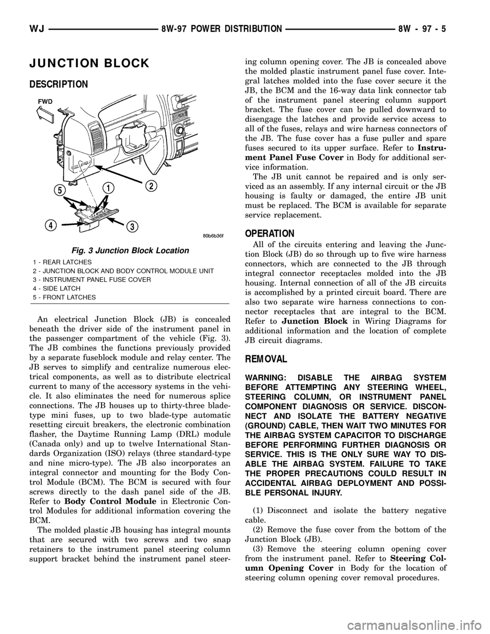
An electrical Junction Block (JB) is concealed
beneath the driver side of the instrument panel in
the passenger compartment of the vehicle (Fig. 3).
The JB combines the functions previously provided
by a separate fuseblock module and relay center. The
JB serves to simplify and centralize numerous elec-
trical components, as well as to distribute electrical
current to many of the accessory systems in the vehi-
cle. It also eliminates the need for numerous splice
connections. The JB houses up to thirty-three blade-
type mini fuses, up to two blade-type automatic
resetting circuit breakers, the electronic combination
flasher, the Daytime Running Lamp (DRL) module
(Canada only) and up to twelve International Stan-
dards Organization (ISO) relays (three standard-type
and nine micro-type). The JB also incorporates an
integral connector and mounting for the Body Con-
trol Module (BCM). The BCM is secured with four
screws directly to the dash panel side of the JB.
Refer toBody Control Modulein Electronic Con-
trol Modules for additional information covering the
BCM.
The molded plastic JB housing has integral mounts
that are secured with two screws and two snap
retainers to the instrument panel steering column
support bracket behind the instrument panel steer-ing column opening cover. The JB is concealed above
the molded plastic instrument panel fuse cover. Inte-
gral latches molded into the fuse cover secure it the
JB, the BCM and the 16-way data link connector tab
of the instrument panel steering column support
bracket. The fuse cover can be pulled downward to
disengage the latches and provide service access to
all of the fuses, relays and wire harness connectors of
the JB. The fuse cover has a fuse puller and spare
fuses secured to its upper surface. Refer toInstru-
ment Panel Fuse Coverin Body for additional ser-
vice information.
The JB unit cannot be repaired and is only ser-
viced as an assembly. If any internal circuit or the JB
housing is faulty or damaged, the entire JB unit
must be replaced. The BCM is available for separate
service replacement.
OPERATION
All of the circuits entering and leaving the Junc-
tion Block (JB) do so through up to five wire harness
connectors, which are connected to the JB through
integral connector receptacles molded into the JB
housing. Internal connection of all of the JB circuits
is accomplished by a printed circuit board. There are
also two separate wire harness connections to con-
nector receptacles that are integral to the BCM.
Refer toJunction Blockin Wiring Diagrams for
additional information and the location of complete
JB circuit diagrams.
REMOVAL
WARNING: DISABLE THE AIRBAG SYSTEM
BEFORE ATTEMPTING ANY STEERING WHEEL,
STEERING COLUMN, OR INSTRUMENT PANEL
COMPONENT DIAGNOSIS OR SERVICE. DISCON-
NECT AND ISOLATE THE BATTERY NEGATIVE
(GROUND) CABLE, THEN WAIT TWO MINUTES FOR
THE AIRBAG SYSTEM CAPACITOR TO DISCHARGE
BEFORE PERFORMING FURTHER DIAGNOSIS OR
SERVICE. THIS IS THE ONLY SURE WAY TO DIS-
ABLE THE AIRBAG SYSTEM. FAILURE TO TAKE
THE PROPER PRECAUTIONS COULD RESULT IN
ACCIDENTAL AIRBAG DEPLOYMENT AND POSSI-
BLE PERSONAL INJURY.
(1) Disconnect and isolate the battery negative
cable.
(2) Remove the fuse cover from the bottom of the
Junction Block (JB).
(3) Remove the steering column opening cover
from the instrument panel. Refer toSteering Col-
umn Opening Coverin Body for the location of
steering column opening cover removal procedures.
Fig. 3 Junction Block Location
1 - REAR LATCHES
2 - JUNCTION BLOCK AND BODY CONTROL MODULE UNIT
3 - INSTRUMENT PANEL FUSE COVER
4 - SIDE LATCH
5 - FRONT LATCHES
WJ8W-97 POWER DISTRIBUTION 8W - 97 - 5
Page 1231 of 2199
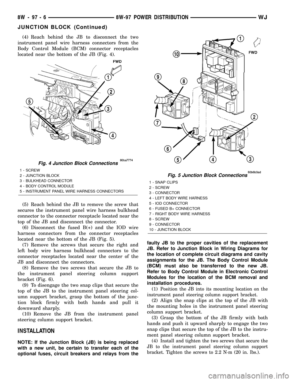
(4) Reach behind the JB to disconnect the two
instrument panel wire harness connectors from the
Body Control Module (BCM) connector receptacles
located near the bottom of the JB (Fig. 4).
(5) Reach behind the JB to remove the screw that
secures the instrument panel wire harness bulkhead
connector to the connector receptacle located near the
top of the JB and disconnect the connector.
(6) Disconnect the fused B(+) and the IOD wire
harness connectors from the connector receptacles
located near the bottom of the JB (Fig. 5).
(7) Remove the screws that secure the right and
left body wire harness bulkhead connectors to the
connector receptacles located near the center of the
JB and disconnect the connectors.
(8) Remove the two screws that secure the JB to
the instrument panel steering column support
bracket (Fig. 6).
(9) To disengage the two snap clips that secure the
top of the JB to the instrument panel steering col-
umn support bracket, grasp the bottom of the junc-
tion block firmly with both hands and pull it
downward sharply.
(10) Remove the JB from the instrument panel
steering column support bracket.
INSTALLATION
NOTE: If the Junction Block (JB) is being replaced
with a new unit, be certain to transfer each of the
optional fuses, circuit breakers and relays from thefaulty JB to the proper cavities of the replacement
JB. Refer to Junction Block in Wiring Diagrams for
the location of complete circuit diagrams and cavity
assignments for the JB. The Body Control Module
(BCM) must also be transferred to the new JB.
Refer to Body Control Module in Electronic Control
Modules for the location of the BCM removal and
installation procedures.
(1)
Position the JB into its mounting location on the
instrument panel steering column support bracket.
(2) Align the snap clips at the top of the JB with
the mounting holes in the instrument panel steering
column support bracket.
(3) Grasp the bottom of the JB firmly with both
hands and push it upward sharply to engage the two
snap clips that secure the top of the JB to the instru-
ment panel steering column support bracket.
(4)
Install and tighten the two screws that secure the
JB to the instrument panel steering column support
bracket. Tighten the screws to 2.2 N´m (20 in. lbs.).
Fig. 4 Junction Block Connections
1 - SCREW
2 - JUNCTION BLOCK
3 - BULKHEAD CONNECTOR
4 - BODY CONTROL MODULE
5 - INSTRUMENT PANEL WIRE HARNESS CONNECTORS
Fig. 5 Junction Block Connections
1 - SNAP CLIPS
2 - SCREW
3 - CONNECTOR
4 - LEFT BODY WIRE HARNESS
5 - IOD CONNECTOR
6 - FUSED B+ CONNECTOR
7 - RIGHT BODY WIRE HARNESS
8 - SCREW
9 - CONNECTOR
10 - JUNCTION BLOCK
8W - 97 - 6 8W-97 POWER DISTRIBUTIONWJ
JUNCTION BLOCK (Continued)