2002 JEEP GRAND CHEROKEE air bag
[x] Cancel search: air bagPage 1149 of 2199
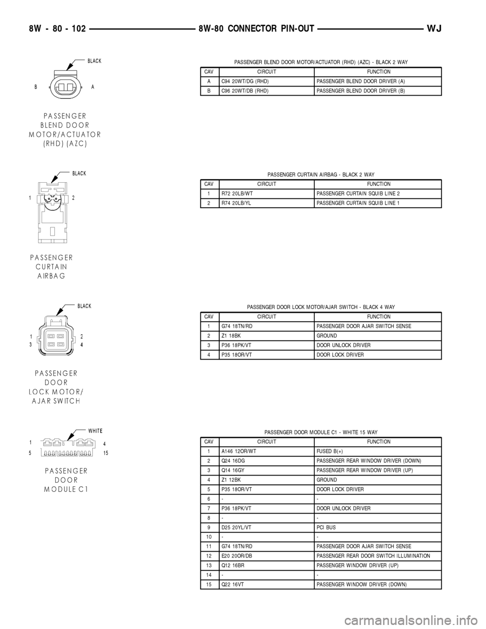
PASSENGER BLEND DOOR MOTOR/ACTUATOR (RHD) (AZC) - BLACK 2 WAY
CAV CIRCUIT FUNCTION
A C94 20WT/DG (RHD) PASSENGER BLEND DOOR DRIVER (A)
B C96 20WT/DB (RHD) PASSENGER BLEND DOOR DRIVER (B)
PASSENGER CURTAIN AIRBAG - BLACK 2 WAY
CAV CIRCUIT FUNCTION
1 R72 20LB/WT PASSENGER CURTAIN SQUIB LINE 2
2 R74 20LB/YL PASSENGER CURTAIN SQUIB LINE 1
PASSENGER DOOR LOCK MOTOR/AJAR SWITCH - BLACK 4 WAY
CAV CIRCUIT FUNCTION
1 G74 18TN/RD PASSENGER DOOR AJAR SWITCH SENSE
2 Z1 18BK GROUND
3 P36 18PK/VT DOOR UNLOCK DRIVER
4 P35 18OR/VT DOOR LOCK DRIVER
PASSENGER DOOR MODULE C1 - WHITE 15 WAY
CAV CIRCUIT FUNCTION
1 A146 12OR/WT FUSED B(+)
2 Q24 16DG PASSENGER REAR WINDOW DRIVER (DOWN)
3 Q14 16GY PASSENGER REAR WINDOW DRIVER (UP)
4 Z1 12BK GROUND
5 P35 18OR/VT DOOR LOCK DRIVER
6- -
7 P36 18PK/VT DOOR UNLOCK DRIVER
8- -
9 D25 20YL/VT PCI BUS
10 - -
11 G74 18TN/RD PASSENGER DOOR AJAR SWITCH SENSE
12 E20 20OR/DB PASSENGER REAR DOOR SWITCH ILLUMINATION
13 Q12 16BR PASSENGER WINDOW DRIVER (UP)
14 - -
15 Q22 16VT PASSENGER WINDOW DRIVER (DOWN)
8W - 80 - 102 8W-80 CONNECTOR PIN-OUTWJ
Page 1176 of 2199
8W-91 CONNECTOR/GROUND/SPLICE LOCATION
TABLE OF CONTENTS
page
CONNECTOR/GROUND/SPLICE LOCATION
DESCRIPTION..........................1
CONNECTOR/GROUND/SPLICE
LOCATION
DESCRIPTION
This section provides illustrations identifying con-
nector, ground, and splice locations in the vehicle.Connector, ground, and splice indexes are provided.
Use the wiring diagrams in each section for connec-
tor, ground, and splice identification. Refer to the
appropriate index for the proper figure number. For
items that are not shown in this section N/S is placed
in the Fig. column.
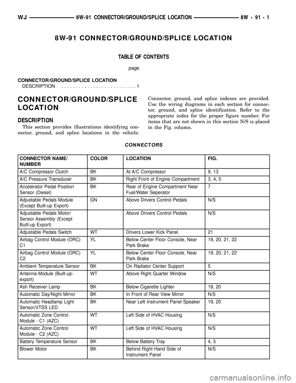
CONNECTORS
CONNECTOR NAME/
NUMBERCOLOR LOCATION FIG.
A/C Compressor Clutch BK At A/C Compressor 9, 13
A/C Pressure Transducer BK Right Front of Engine Compartment 3, 4, 5
Accelerator Pedal Position
Sensor (Diesel)BK Rear of Engine Compartment Near
Fuel/Water Seperator7
Adjustable Pedals Module
(Except Built-up Export)GN Above Drivers Control Pedals N/S
Adjustable Pedals Motor/
Sensor Assembly (Except
Built-up Export)Above Drivers Control Pedals N/S
Adjustable Pedals Switch WT Drivers Lower Kick Panel 21
Airbag Control Module (ORC)
C1YL Below Center Floor Console, Near
Park Brake19, 20, 21, 22
Airbag Control Module (ORC)
C2YL Below Center Floor Console, Near
Park Brake19, 20, 21, 22
Ambient Temperature Sensor BK On Radiator Center Support 5
Antenna Module (Built-up-
export)WT Above Right Quarter Window N/S
Ash Receiver Lamp BK Below Cigarette Lighter 19, 20
Automatic Day/Night Mirror BK In Front of Rear View Mirror N/S
Automatic Headlamp Light
Sensor/VTSS LEDBK Near Left Instrument Panel Speaker 19, 20
Automatic Zone Control
Module - C1 (AZC)WT Left Side of HVAC Housing N/S
Automatic Zone Control
Module - C2 (AZC)WT Left Side of HVAC Housing N/S
Battery Temperature Sensor BK Below Battery Tray 4, 5
Blower Motor BK Behind Right Hand Side of
Instrument PanelN/S
WJ8W-91 CONNECTOR/GROUND/SPLICE LOCATION 8W - 91 - 1
Page 1179 of 2199
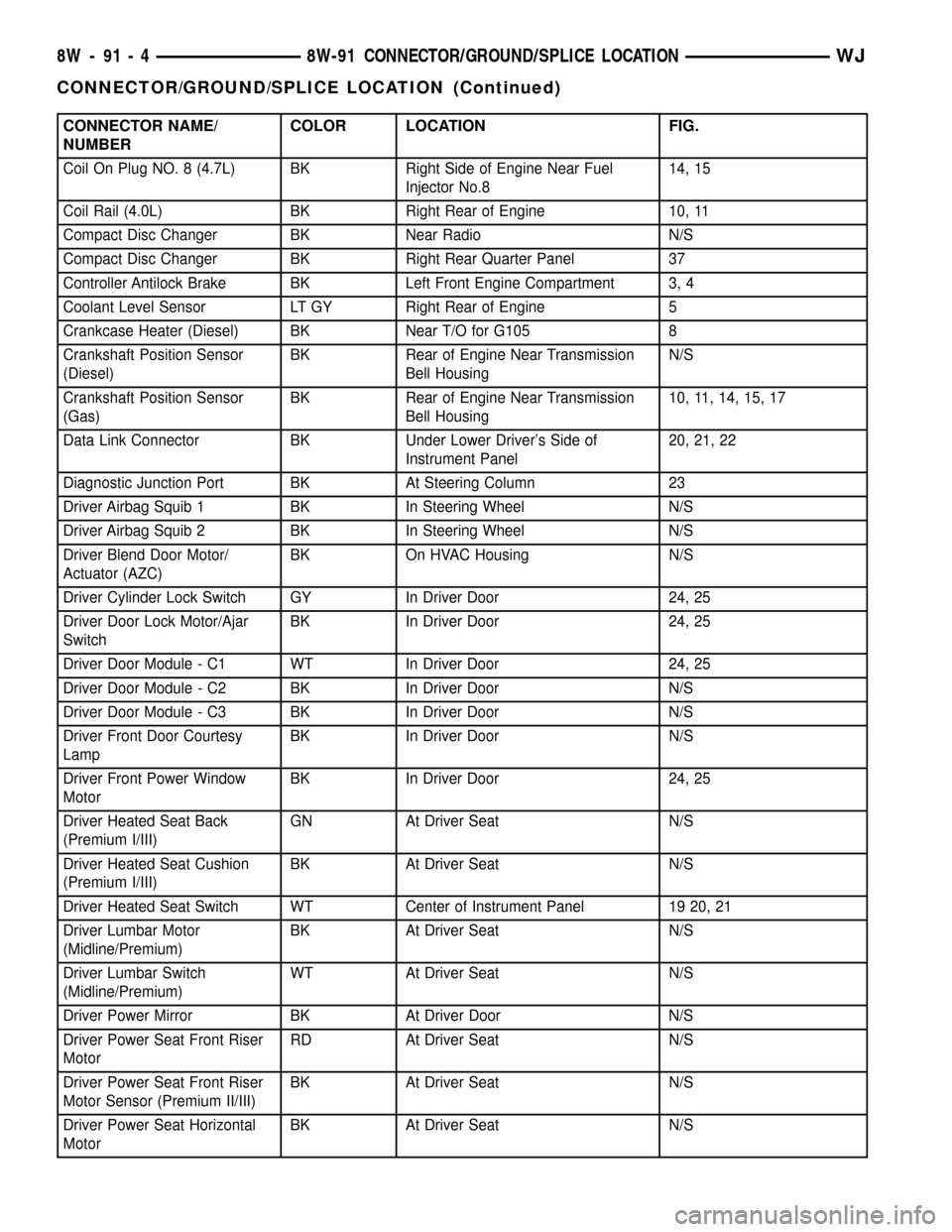
CONNECTOR NAME/
NUMBERCOLOR LOCATION FIG.
Coil On Plug NO. 8 (4.7L) BK Right Side of Engine Near Fuel
Injector No.814, 15
Coil Rail (4.0L) BK Right Rear of Engine 10, 11
Compact Disc Changer BK Near Radio N/S
Compact Disc Changer BK Right Rear Quarter Panel 37
Controller Antilock Brake BK Left Front Engine Compartment 3, 4
Coolant Level Sensor LT GY Right Rear of Engine 5
Crankcase Heater (Diesel) BK Near T/O for G105 8
Crankshaft Position Sensor
(Diesel)BK Rear of Engine Near Transmission
Bell HousingN/S
Crankshaft Position Sensor
(Gas)BK Rear of Engine Near Transmission
Bell Housing10, 11, 14, 15, 17
Data Link Connector BK Under Lower Driver's Side of
Instrument Panel20, 21, 22
Diagnostic Junction Port BK At Steering Column 23
Driver Airbag Squib 1 BK In Steering Wheel N/S
Driver Airbag Squib 2 BK In Steering Wheel N/S
Driver Blend Door Motor/
Actuator (AZC)BK On HVAC Housing N/S
Driver Cylinder Lock Switch GY In Driver Door 24, 25
Driver Door Lock Motor/Ajar
SwitchBK In Driver Door 24, 25
Driver Door Module - C1 WT In Driver Door 24, 25
Driver Door Module - C2 BK In Driver Door N/S
Driver Door Module - C3 BK In Driver Door N/S
Driver Front Door Courtesy
LampBK In Driver Door N/S
Driver Front Power Window
MotorBK In Driver Door 24, 25
Driver Heated Seat Back
(Premium I/III)GN At Driver Seat N/S
Driver Heated Seat Cushion
(Premium I/III)BK At Driver Seat N/S
Driver Heated Seat Switch WT Center of Instrument Panel 19 20, 21
Driver Lumbar Motor
(Midline/Premium)BK At Driver Seat N/S
Driver Lumbar Switch
(Midline/Premium)WT At Driver Seat N/S
Driver Power Mirror BK At Driver Door N/S
Driver Power Seat Front Riser
MotorRD At Driver Seat N/S
Driver Power Seat Front Riser
Motor Sensor (Premium II/III)BK At Driver Seat N/S
Driver Power Seat Horizontal
MotorBK At Driver Seat N/S
8W - 91 - 4 8W-91 CONNECTOR/GROUND/SPLICE LOCATIONWJ
CONNECTOR/GROUND/SPLICE LOCATION (Continued)
Page 1181 of 2199
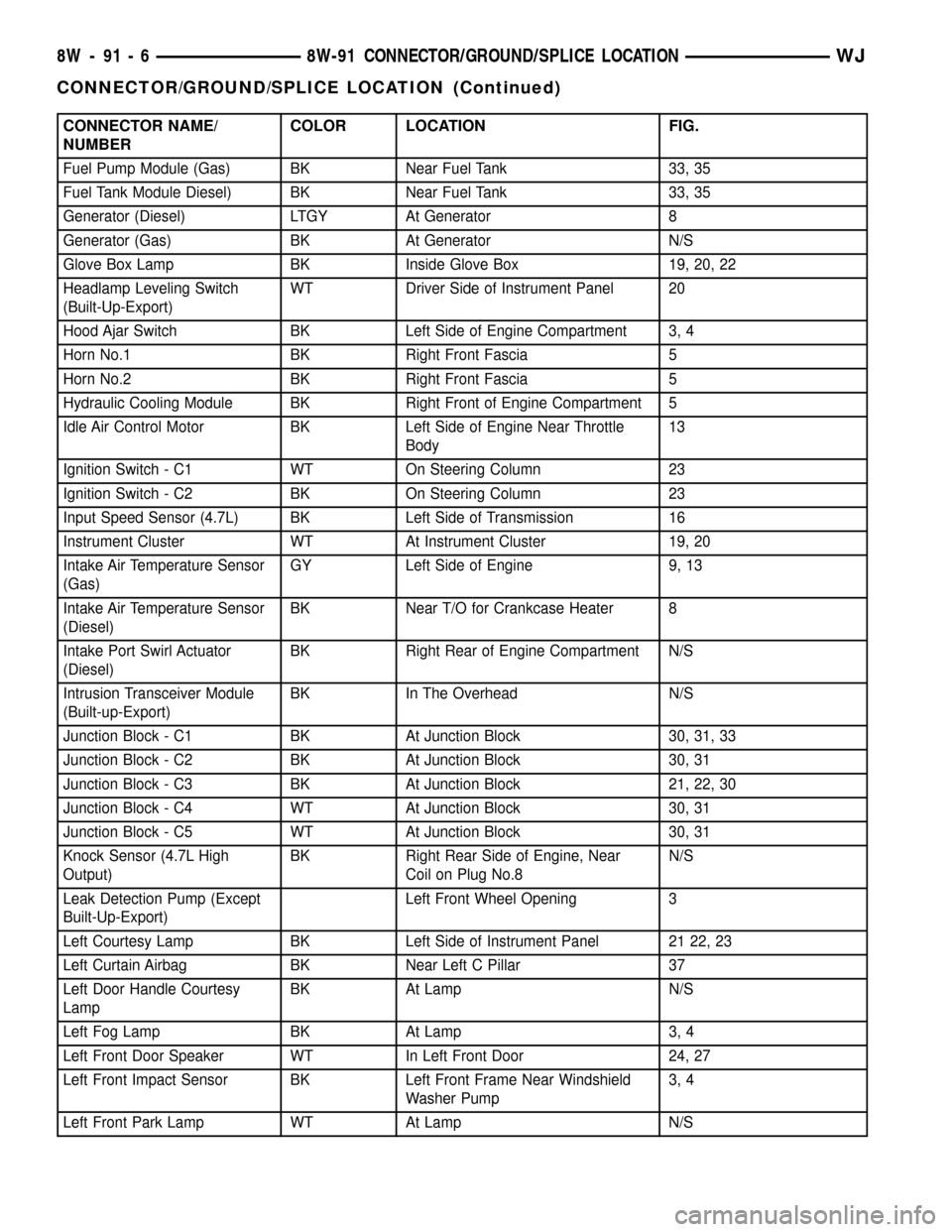
CONNECTOR NAME/
NUMBERCOLOR LOCATION FIG.
Fuel Pump Module (Gas) BK Near Fuel Tank 33, 35
Fuel Tank Module Diesel) BK Near Fuel Tank 33, 35
Generator (Diesel) LTGY At Generator 8
Generator (Gas) BK At Generator N/S
Glove Box Lamp BK Inside Glove Box 19, 20, 22
Headlamp Leveling Switch
(Built-Up-Export)WT Driver Side of Instrument Panel 20
Hood Ajar Switch BK Left Side of Engine Compartment 3, 4
Horn No.1 BK Right Front Fascia 5
Horn No.2 BK Right Front Fascia 5
Hydraulic Cooling Module BK Right Front of Engine Compartment 5
Idle Air Control Motor BK Left Side of Engine Near Throttle
Body13
Ignition Switch - C1 WT On Steering Column 23
Ignition Switch - C2 BK On Steering Column 23
Input Speed Sensor (4.7L) BK Left Side of Transmission 16
Instrument Cluster WT At Instrument Cluster 19, 20
Intake Air Temperature Sensor
(Gas)GY Left Side of Engine 9, 13
Intake Air Temperature Sensor
(Diesel)BK Near T/O for Crankcase Heater 8
Intake Port Swirl Actuator
(Diesel)BK Right Rear of Engine Compartment N/S
Intrusion Transceiver Module
(Built-up-Export)BK In The Overhead N/S
Junction Block - C1 BK At Junction Block 30, 31, 33
Junction Block - C2 BK At Junction Block 30, 31
Junction Block - C3 BK At Junction Block 21, 22, 30
Junction Block - C4 WT At Junction Block 30, 31
Junction Block - C5 WT At Junction Block 30, 31
Knock Sensor (4.7L High
Output)BK Right Rear Side of Engine, Near
Coil on Plug No.8N/S
Leak Detection Pump (Except
Built-Up-Export)Left Front Wheel Opening 3
Left Courtesy Lamp BK Left Side of Instrument Panel 21 22, 23
Left Curtain Airbag BK Near Left C Pillar 37
Left Door Handle Courtesy
LampBK At Lamp N/S
Left Fog Lamp BK At Lamp 3, 4
Left Front Door Speaker WT In Left Front Door 24, 27
Left Front Impact Sensor BK Left Front Frame Near Windshield
Washer Pump3, 4
Left Front Park Lamp WT At Lamp N/S
8W - 91 - 6 8W-91 CONNECTOR/GROUND/SPLICE LOCATIONWJ
CONNECTOR/GROUND/SPLICE LOCATION (Continued)
Page 1183 of 2199
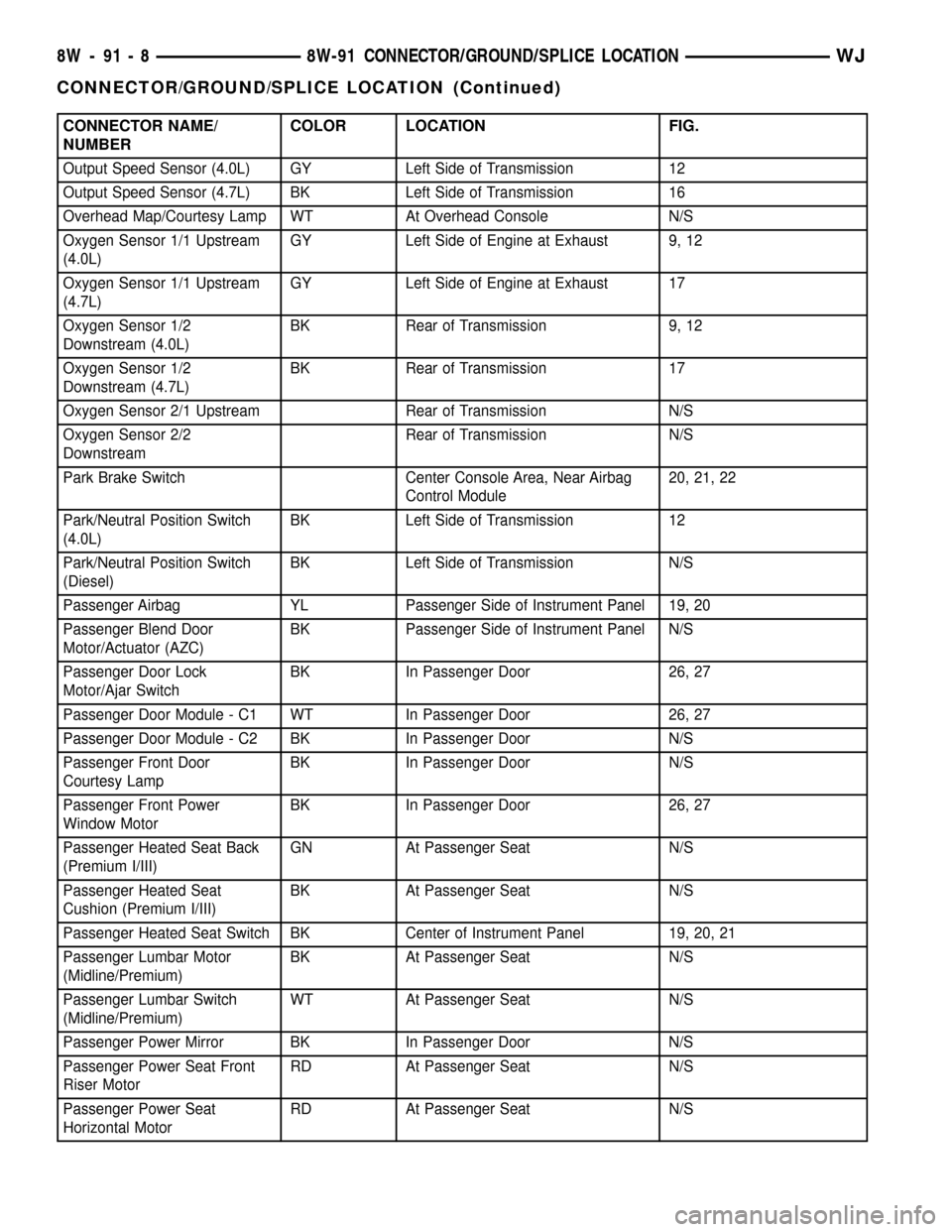
CONNECTOR NAME/
NUMBERCOLOR LOCATION FIG.
Output Speed Sensor (4.0L) GY Left Side of Transmission 12
Output Speed Sensor (4.7L) BK Left Side of Transmission 16
Overhead Map/Courtesy Lamp WT At Overhead Console N/S
Oxygen Sensor 1/1 Upstream
(4.0L)GY Left Side of Engine at Exhaust 9, 12
Oxygen Sensor 1/1 Upstream
(4.7L)GY Left Side of Engine at Exhaust 17
Oxygen Sensor 1/2
Downstream (4.0L)BK Rear of Transmission 9, 12
Oxygen Sensor 1/2
Downstream (4.7L)BK Rear of Transmission 17
Oxygen Sensor 2/1 Upstream Rear of Transmission N/S
Oxygen Sensor 2/2
DownstreamRear of Transmission N/S
Park Brake Switch Center Console Area, Near Airbag
Control Module20, 21, 22
Park/Neutral Position Switch
(4.0L)BK Left Side of Transmission 12
Park/Neutral Position Switch
(Diesel)BK Left Side of Transmission N/S
Passenger Airbag YL Passenger Side of Instrument Panel 19, 20
Passenger Blend Door
Motor/Actuator (AZC)BK Passenger Side of Instrument Panel N/S
Passenger Door Lock
Motor/Ajar SwitchBK In Passenger Door 26, 27
Passenger Door Module - C1 WT In Passenger Door 26, 27
Passenger Door Module - C2 BK In Passenger Door N/S
Passenger Front Door
Courtesy LampBK In Passenger Door N/S
Passenger Front Power
Window MotorBK In Passenger Door 26, 27
Passenger Heated Seat Back
(Premium I/III)GN At Passenger Seat N/S
Passenger Heated Seat
Cushion (Premium I/III)BK At Passenger Seat N/S
Passenger Heated Seat Switch BK Center of Instrument Panel 19, 20, 21
Passenger Lumbar Motor
(Midline/Premium)BK At Passenger Seat N/S
Passenger Lumbar Switch
(Midline/Premium)WT At Passenger Seat N/S
Passenger Power Mirror BK In Passenger Door N/S
Passenger Power Seat Front
Riser MotorRD At Passenger Seat N/S
Passenger Power Seat
Horizontal MotorRD At Passenger Seat N/S
8W - 91 - 8 8W-91 CONNECTOR/GROUND/SPLICE LOCATIONWJ
CONNECTOR/GROUND/SPLICE LOCATION (Continued)
Page 1184 of 2199
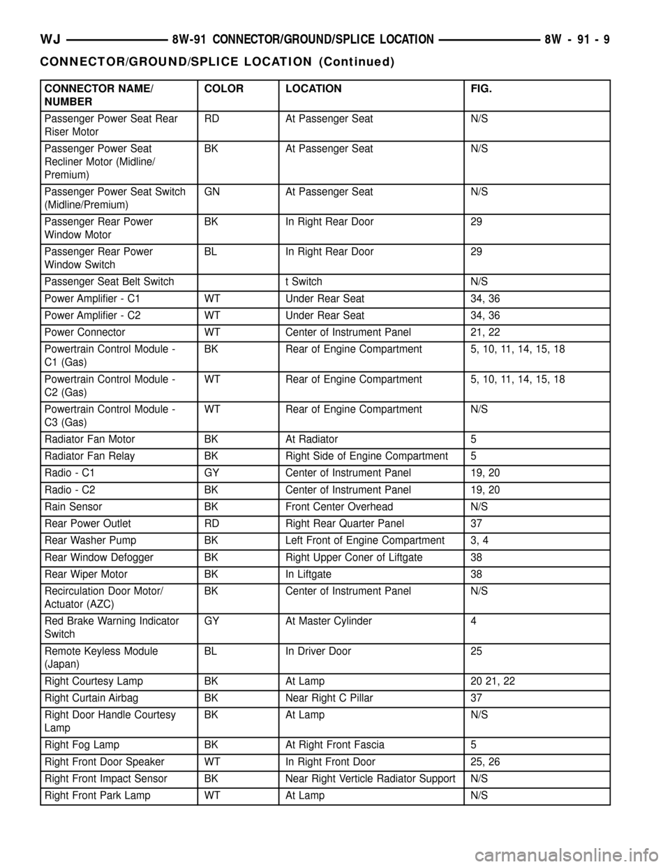
CONNECTOR NAME/
NUMBERCOLOR LOCATION FIG.
Passenger Power Seat Rear
Riser MotorRD At Passenger Seat N/S
Passenger Power Seat
Recliner Motor (Midline/
Premium)BK At Passenger Seat N/S
Passenger Power Seat Switch
(Midline/Premium)GN At Passenger Seat N/S
Passenger Rear Power
Window MotorBK In Right Rear Door 29
Passenger Rear Power
Window SwitchBL In Right Rear Door 29
Passenger Seat Belt Switch t Switch N/S
Power Amplifier - C1 WT Under Rear Seat 34, 36
Power Amplifier - C2 WT Under Rear Seat 34, 36
Power Connector WT Center of Instrument Panel 21, 22
Powertrain Control Module -
C1 (Gas)BK Rear of Engine Compartment 5, 10, 11, 14, 15, 18
Powertrain Control Module -
C2 (Gas)WT Rear of Engine Compartment 5, 10, 11, 14, 15, 18
Powertrain Control Module -
C3 (Gas)WT Rear of Engine Compartment N/S
Radiator Fan Motor BK At Radiator 5
Radiator Fan Relay BK Right Side of Engine Compartment 5
Radio - C1 GY Center of Instrument Panel 19, 20
Radio - C2 BK Center of Instrument Panel 19, 20
Rain Sensor BK Front Center Overhead N/S
Rear Power Outlet RD Right Rear Quarter Panel 37
Rear Washer Pump BK Left Front of Engine Compartment 3, 4
Rear Window Defogger BK Right Upper Coner of Liftgate 38
Rear Wiper Motor BK In Liftgate 38
Recirculation Door Motor/
Actuator (AZC)BK Center of Instrument Panel N/S
Red Brake Warning Indicator
SwitchGY At Master Cylinder 4
Remote Keyless Module
(Japan)BL In Driver Door 25
Right Courtesy Lamp BK At Lamp 20 21, 22
Right Curtain Airbag BK Near Right C Pillar 37
Right Door Handle Courtesy
LampBK At Lamp N/S
Right Fog Lamp BK At Right Front Fascia 5
Right Front Door Speaker WT In Right Front Door 25, 26
Right Front Impact Sensor BK Near Right Verticle Radiator Support N/S
Right Front Park Lamp WT At Lamp N/S
WJ8W-91 CONNECTOR/GROUND/SPLICE LOCATION 8W - 91 - 9
CONNECTOR/GROUND/SPLICE LOCATION (Continued)
Page 1186 of 2199
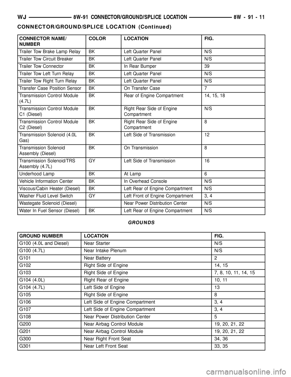
CONNECTOR NAME/
NUMBERCOLOR LOCATION FIG.
Trailer Tow Brake Lamp Relay BK Left Quarter Panel N/S
Trailer Tow Circuit Breaker BK Left Quarter Panel N/S
Trailer Tow Connector BK In Rear Bumper 39
Trailer Tow Left Turn Relay BK Left Quarter Panel N/S
Trailer Tow Right Turn Relay BK Left Quarter Panel N/S
Transfer Case Position Sensor BK On Transfer Case 7
Transmission Control Module
(4.7L)BK Rear of Engine Compartment 14, 15, 18
Transmission Control Module
C1 (Diesel)BK Right Rear Side of Engine
CompartmentN/S
Transmission Control Module
C2 (Diesel)BK Right Rear Side of Engine
Compartment8
Transmission Solenoid (4.0L
Gas)BK Left Side of Transmission 12
Transmission Solenoid
Assembly (Diesel)BK On Transmission 8
Transmission Solenoid/TRS
Assembly (4.7L)GY Left Side of Transmission 16
Underhood Lamp BK At Lamp 6
Vehicle Information Center BK In Overhead Console N/S
Viscous/Cabin Heater (Diesel) BK Left Rear of Engine Compartment N/S
Washer Fluid Level Switch GY Left Front of Engine Compartment 3, 4
Wastegate Solenoid (Diesel) Near Power Distribution Center N/S
Water In Fuel Sensor (Diesel) BK Left Rear of Engine Compartment N/S
GROUNDS
GROUND NUMBER LOCATION FIG.
G100 (4.0L and Diesel) Near Starter N/S
G100 (4.7L) Near Intake Plenum N/S
G101 Near Battery 2
G102 Right Side of Engine 14, 15
G103 Right Side of Engine 7, 8, 10, 11, 14, 15
G104 (4.0L) Right Rear of Engine 10, 11
G104 (4.7L) Left Side of Engine 13
G105 Right Side of Engine 8
G106 Left Side of Engine Compartment 3, 4
G107 Left Side of Engine Compartment 3, 4
G108 Near Power Distribution Center 5
G200 Near Airbag Control Module 19, 20, 21, 22
G201 Near Airbag Control Module 19, 20, 21, 22
G300 Near Right Front Seat 34, 36
G301 Near Left Front Seat 33, 35
WJ8W-91 CONNECTOR/GROUND/SPLICE LOCATION 8W - 91 - 11
CONNECTOR/GROUND/SPLICE LOCATION (Continued)
Page 1230 of 2199

JUNCTION BLOCK
DESCRIPTION
An electrical Junction Block (JB) is concealed
beneath the driver side of the instrument panel in
the passenger compartment of the vehicle (Fig. 3).
The JB combines the functions previously provided
by a separate fuseblock module and relay center. The
JB serves to simplify and centralize numerous elec-
trical components, as well as to distribute electrical
current to many of the accessory systems in the vehi-
cle. It also eliminates the need for numerous splice
connections. The JB houses up to thirty-three blade-
type mini fuses, up to two blade-type automatic
resetting circuit breakers, the electronic combination
flasher, the Daytime Running Lamp (DRL) module
(Canada only) and up to twelve International Stan-
dards Organization (ISO) relays (three standard-type
and nine micro-type). The JB also incorporates an
integral connector and mounting for the Body Con-
trol Module (BCM). The BCM is secured with four
screws directly to the dash panel side of the JB.
Refer toBody Control Modulein Electronic Con-
trol Modules for additional information covering the
BCM.
The molded plastic JB housing has integral mounts
that are secured with two screws and two snap
retainers to the instrument panel steering column
support bracket behind the instrument panel steer-ing column opening cover. The JB is concealed above
the molded plastic instrument panel fuse cover. Inte-
gral latches molded into the fuse cover secure it the
JB, the BCM and the 16-way data link connector tab
of the instrument panel steering column support
bracket. The fuse cover can be pulled downward to
disengage the latches and provide service access to
all of the fuses, relays and wire harness connectors of
the JB. The fuse cover has a fuse puller and spare
fuses secured to its upper surface. Refer toInstru-
ment Panel Fuse Coverin Body for additional ser-
vice information.
The JB unit cannot be repaired and is only ser-
viced as an assembly. If any internal circuit or the JB
housing is faulty or damaged, the entire JB unit
must be replaced. The BCM is available for separate
service replacement.
OPERATION
All of the circuits entering and leaving the Junc-
tion Block (JB) do so through up to five wire harness
connectors, which are connected to the JB through
integral connector receptacles molded into the JB
housing. Internal connection of all of the JB circuits
is accomplished by a printed circuit board. There are
also two separate wire harness connections to con-
nector receptacles that are integral to the BCM.
Refer toJunction Blockin Wiring Diagrams for
additional information and the location of complete
JB circuit diagrams.
REMOVAL
WARNING: DISABLE THE AIRBAG SYSTEM
BEFORE ATTEMPTING ANY STEERING WHEEL,
STEERING COLUMN, OR INSTRUMENT PANEL
COMPONENT DIAGNOSIS OR SERVICE. DISCON-
NECT AND ISOLATE THE BATTERY NEGATIVE
(GROUND) CABLE, THEN WAIT TWO MINUTES FOR
THE AIRBAG SYSTEM CAPACITOR TO DISCHARGE
BEFORE PERFORMING FURTHER DIAGNOSIS OR
SERVICE. THIS IS THE ONLY SURE WAY TO DIS-
ABLE THE AIRBAG SYSTEM. FAILURE TO TAKE
THE PROPER PRECAUTIONS COULD RESULT IN
ACCIDENTAL AIRBAG DEPLOYMENT AND POSSI-
BLE PERSONAL INJURY.
(1) Disconnect and isolate the battery negative
cable.
(2) Remove the fuse cover from the bottom of the
Junction Block (JB).
(3) Remove the steering column opening cover
from the instrument panel. Refer toSteering Col-
umn Opening Coverin Body for the location of
steering column opening cover removal procedures.
Fig. 3 Junction Block Location
1 - REAR LATCHES
2 - JUNCTION BLOCK AND BODY CONTROL MODULE UNIT
3 - INSTRUMENT PANEL FUSE COVER
4 - SIDE LATCH
5 - FRONT LATCHES
WJ8W-97 POWER DISTRIBUTION 8W - 97 - 5