2002 JEEP GRAND CHEROKEE junction
[x] Cancel search: junctionPage 1242 of 2199
the vehicle. The power outlet base and mount are
secured by a snap fit within the quarter trim panel.
A plastic protective cap snaps into the power outlet
base when the power outlet is not being used, and
hangs from the power outlet base mount by an inte-
gral bail strap while the power outlet is in use. While
the power outlet is very similar to a cigar lighter
base unit, it does not include the two small spring-
clip retainers inside the bottom of the receptacle
shell that are used to secure the cigar lighter heating
element to the insulated contact.
The power outlet receptacle unit and the accessory
power outlet protective cap are available for service.
The power outlet receptacle cannot be repaired and,
if faulty or damaged, it must be replaced.
OPERATION - REAR POWER OUTLET
The power outlet base or receptacle shell is con-
nected to ground, and an insulated contact in the
bottom of the shell is connected to battery current.
The power outlet receives battery voltage from a fuse
in the Power Distribution Center (PDC) through a
fuse in the Junction Block (JB) at all times. Refer to
Horn/Cigar Lighter/Power Outletin Wiring Dia-
grams for the location of complete rear power outlet
circuit diagrams.
DIAGNOSIS AND TESTING - REAR POWER
OUTLET
Refer toHorn/Cigar Lighter/Power Outletin
Wiring Diagrams for the location of complete rear
power outlet circuit diagrams.
(1) Check the fused B(+) fuse in the Junction
Block (JB). If OK, go to Step 2. If not OK, repair the
shorted circuit or component as required and replace
the faulty fuse.
(2) Check for battery voltage at the fused B(+) fuse
in the JB. If OK, go to Step 3. If not OK, repair the
open fused B(+) circuit to the Power Distribution
Center (PDC) as required.
(3) Remove the plastic protective cap from the rear
power outlet receptacle. Check for continuity between
the inside circumference of the rear power outlet
receptacle and a good ground. There should be conti-
nuity. If OK, go to Step 4. If not OK, go to Step 5.
(4) Check for battery voltage at the insulated con-
tact located at the back of the rear power outlet
receptacle. If not OK, go to Step 5.(5) Disconnect and isolate the battery negative
cable. Remove the rear power outlet from the right
quarter trim panel. Check for continuity between the
ground circuit cavity of the rear power outlet wire
harness connector and a good ground. There should
be continuity. If OK, go to Step 6. If not OK, repair
the open ground circuit to ground as required.
(6) Connect the battery negative cable. Check for
battery voltage at the fused B(+) circuit cavity of the
rear power outlet wire harness connector. If OK,
replace the faulty rear power outlet receptacle base.
If not OK, repair the open fused B(+) circuit to the
JB fuse as required.
REMOVAL
(1) Disconnect and isolate the battery negative
cable.
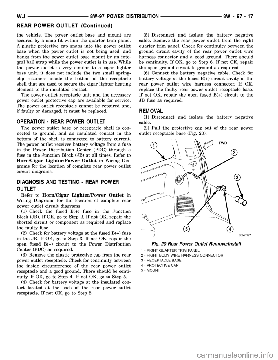
(2) Pull the protective cap out of the rear power
outlet receptacle base (Fig. 20).
Fig. 20 Rear Power Outlet Remove/Install
1 - RIGHT QUARTER TRIM PANEL
2 - RIGHT BODY WIRE HARNESS CONNECTOR
3 - RECEPTACLE BASE
4 - PROTECTIVE CAP
5 - MOUNT
WJ8W-97 POWER DISTRIBUTION 8W - 97 - 17
REAR POWER OUTLET (Continued)
Page 1421 of 2199
FUEL DELIVERY
DESCRIPTION
The fuel delivery system consists of:
²the fuel pump module containing the electric
fuel pump, fuel gauge sending unit (fuel level sensor)
and a separate fuel filter located at bottom of pump
module
²a separate combination fuel filter/fuel pressure
regulator
²fuel tubes/lines/hoses
²quick-connect fittings
²fuel injector rail
²fuel injectors
²fuel tank
²fuel tank filler/vent tube assembly
²fuel tank filler tube cap
²accelerator pedal
²throttle cable
OPERATION
The fuel tank assembly consists of: the fuel tank,
fuel tank shield, fuel tank straps, fuel pump module
assembly, fuel pump module locknut/gasket, and fuel
tank check valve (refer to Emission Control System
for fuel tank check valve information).
A fuel filler/vent tube assembly using a pressure/
vacuum, 1/4 turn fuel filler cap is used. The fuel
filler tube contains a flap door located below the fuel
fill cap.
Also to be considered part of the fuel system is the
evaporation control system. This is designed to
reduce the emission of fuel vapors into the atmo-
sphere. The description and function of the Evapora-
tive Control System is found in Emission Control
Systems.
Both fuel filters (at bottom of fuel pump module
and within fuel pressure regulator) are designed for
extended service. They do not require normal sched-
uled maintenance. Filters should only be replaced if
a diagnostic procedure indicates to do so.
DIAGNOSIS AND TESTING
FUEL PRESSURE LEAK DOWN TEST
Use this test in conjunction with the Fuel Pump
Pressure Test and Fuel Pump Capacity Test.
Check Valve Operation:The electric fuel pump
outlet contains a one-way check valve to prevent fuel
flow back into the tank and to maintain fuel supply
line pressure (engine warm) when pump is not oper-
ational. It is also used to keep the fuel supply line
full of gasoline when pump is not operational. After
the vehicle has cooled down, fuel pressure may drop
to 0 psi (cold fluid contracts), but liquid gasoline willremain in fuel supply line between the check valve
and fuel injectors.Fuel pressure that has
dropped to 0 psi on a cooled down vehicle
(engine off) is a normal condition.When the elec-
tric fuel pump is activated, fuel pressure should
immediately(1±2 seconds) rise to specification.
Abnormally long periods of cranking to restart a
hotengine that has been shut down for a short
period of time may be caused by:
²Fuel pressure bleeding past a fuel injector(s).
²Fuel pressure bleeding past the check valve in
the fuel pump module.
²A defective fuel filter/pressure regulator.
Two #6539, 5/16º, Fuel Line Pressure Test Adapter
Hose Tools are required for the following tests.
(1) Release fuel system pressure. Refer to Fuel
Pressure Release Procedure.
(2) Raise vehicle.
Fuel Line Identification:The fuel filter/pressure
regulator is located in front of the fuel tank and
above the rear axle. It is transversely mounted to a
chassis crossmember (left-to-right). The filter/regula-
tor is equipped with 3 fuel line fittings (2 at one end
and 1 at the other end). The single fitting facing the
left side of the vehicle is the supply line to the fuel
rail (Fig. 1) . The 2 fittings facing the right side of
the vehicle are connected to the fuel tank. Of these 2
fittings, the fitting towards thefrontis used for fuel
return to the fuel tank. The fitting towards therear
is a pressure line. Thisrearfitting must be discon-
nected for the following step.
(3) See previous step. Disconnect fuel pressure line
atrearof filter/regulator. This is a 5/169quick-con-
nect fitting (Fig. 1) . Refer to Quick-Connect Fittings
for procedures.
(4) Obtain correct Fuel Line Pressure Test Adapter
Hose Tool # 6539 for 5/16º fuel lines. Connect one
end of this Special Tool into the disconnected fuel
pressure line. Connect the other end of the Tool into
fitting on filter/regulator.
(5) Lower vehicle.
(6) Disconnect the fuel inlet line at fuel rail. Refer
to Quick-Connect Fittings for procedures. On some
engines, air cleaner housing removal may be neces-
sary before fuel line disconnection.
(7) Obtain a second Fuel Line Pressure Test
Adapter Hose Tool # 6539 for 5/16º fuel lines. Con-
nect this tool between disconnected fuel line and fuel
rail (Fig. 2) .
(8) Connect the 0-414 kPa (0-60 psi) fuel pressure
test gauge (from Gauge Set 5069) to the test port on
the appropriate Adaptor Tool.NOTE: The DRB III
Scan Tool along with the PEP module, the 500
psi pressure transducer, and the transducer-to-
test port adapter may also be used in place of
the fuel pressure gauge.
14 - 2 FUEL DELIVERYWJ
Page 1428 of 2199
OPERATION
Voltage to operate the electric pump is supplied
through the fuel pump relay.
Fuel is drawn in through a filter at the bottom of
the module and pushed through the electric motor
gearset to the pump outlet.
Check Valve Operation:The pump outlet con-
tains a one-way check valve to prevent fuel flow back
into the tank and to maintain fuel supply line pres-
sure (engine warm) when pump is not operational. It
is also used to keep the fuel supply line full of gaso-
line when pump is not operational. After the vehicle
has cooled down, fuel pressure may drop to 0 psi
(cold fluid contracts), but liquid gasoline will remain
in fuel supply line between the check valve and fuel
injectors.Fuel pressure that has dropped to 0
psi on a cooled down vehicle (engine off) is a
normal condition.Refer to the Fuel Pressure Leak
Down Test for more information.
The electric fuel pump is not a separate, service-
able component.
DIAGNOSIS AND TESTING
DIAGNOSIS AND TESTING - FUEL PUMP
CAPACITY TEST
Before performing this test, verify fuel pump
pressure. Refer to Fuel Pump Pressure Test.
Use this test in conjunction with the Fuel Pres-
sure Leak Down Test.
(1) Release fuel system pressure. Refer to Fuel
Pressure Release Procedure.
(2) Disconnect fuel supply line at fuel rail. Refer to
Quick-Connect Fittings. Some engines may require
air cleaner housing removal before line disconnection.
(3) Obtain correct Fuel Line Pressure Test Adapter
Tool Hose. Tool number 6539 is used for 5/16º fuel
lines and tool number 6631 is used for 3/8º fuel lines.
(4) Connect correct Fuel Line Pressure Test
Adapter Tool Hose into disconnected fuel supply line.
Insert other end of Adaptor Tool Hose into a gradu-
ated container.
(5) Remove fuel fill cap.
(6) To activate fuel pump and pressurize system,
obtain DRBtscan tool and actuate ASD Fuel System
Test.
(7) A good fuel pump will deliver at least 1/4 liter
of fuel in 7 seconds. Do not operate fuel pump for
longer than 7 seconds with fuel line disconnected as
fuel pump module reservoir may run empty.
(a) If capacity is lower than specification, but
fuel pump can be heard operating through fuel fill
cap opening, check for a kinked/damaged fuel sup-
ply line somewhere between fuel rail and fuel
pump module.(b) If line is not kinked/damaged, and fuel pres-
sure is OK, but capacity is low, replace fuel filter/
fuel pressure regulator. The filter/regulator may be
serviced separately on certain applications. Refer
to Fuel Filter/Fuel Pressure Regulator Removal/In-
stallation for additional information.
(c) If both fuel pressure and capacity are low,
replace fuel pump module assembly. Refer to Fuel
Pump Module Removal/Installation.
DIAGNOSIS AND TESTING - FUEL PUMP
AMPERAGE TEST
This amperage (current draw) test is to be done in
conjunction with the Fuel Pump Pressure Test, Fuel
Pump Capacity Test and Fuel Pressure Leak Down
Test. Before performing the amperage test, be sure
the temperature of the fuel tank is above 50É F (10É
C).
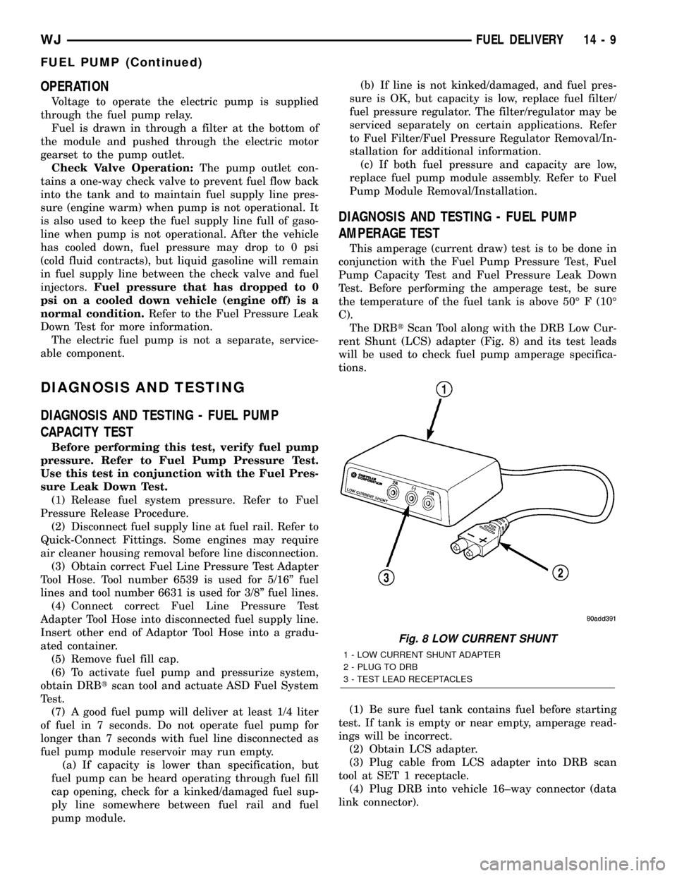
The DRBtScan Tool along with the DRB Low Cur-
rent Shunt (LCS) adapter (Fig. 8) and its test leads
will be used to check fuel pump amperage specifica-
tions.
(1) Be sure fuel tank contains fuel before starting
test. If tank is empty or near empty, amperage read-
ings will be incorrect.
(2) Obtain LCS adapter.
(3) Plug cable from LCS adapter into DRB scan
tool at SET 1 receptacle.
(4) Plug DRB into vehicle 16±way connector (data
link connector).
Fig. 8 LOW CURRENT SHUNT
1 - LOW CURRENT SHUNT ADAPTER
2 - PLUG TO DRB
3 - TEST LEAD RECEPTACLES
WJFUEL DELIVERY 14 - 9
FUEL PUMP (Continued)
Page 1430 of 2199
(19) Disconnect test leads from relay cavities
immediately after testing.
FUEL PUMP PRESSURE TEST
Use this test in conjunction with other fuel system
tests. Refer to the Fuel Pump Capacity Test, Fuel
Pressure Leak Down Test and Fuel Pump Amperage
Test.
Check Valve Operation:The electric fuel pump
outlet contains a one-way check valve to prevent fuel
flow back into the tank and to maintain fuel supply
line pressure (engine warm) when pump is not oper-
ational. It is also used to keep the fuel supply line
full of gasoline when pump is not operational. After
the vehicle has cooled down, fuel pressure may drop
to 0 psi (cold fluid contracts), but liquid gasoline will
remain in fuel supply line between the check valve
and fuel injectors.Fuel pressure that has
dropped to 0 psi on a cooled down vehicle
(engine off) is a normal condition.When the elec-
tric fuel pump is activated, fuel pressure should
immediately(1±2 seconds) rise to specification.
The fuel system is equipped with a combination
fuel filter/fuel pressure regulator. The fuel pressure
regulator is not controlled by engine vacuum.
WARNING: THE FUEL SYSTEM IS UNDER CON-
STANT FUEL PRESSURE EVEN WITH THE ENGINE
OFF. BEFORE DISCONNECTING FUEL LINE AT
FUEL RAIL, THIS PRESSURE MUST BE RELEASED.REFER TO THE FUEL SYSTEM PRESSURE
RELEASE PROCEDURE.
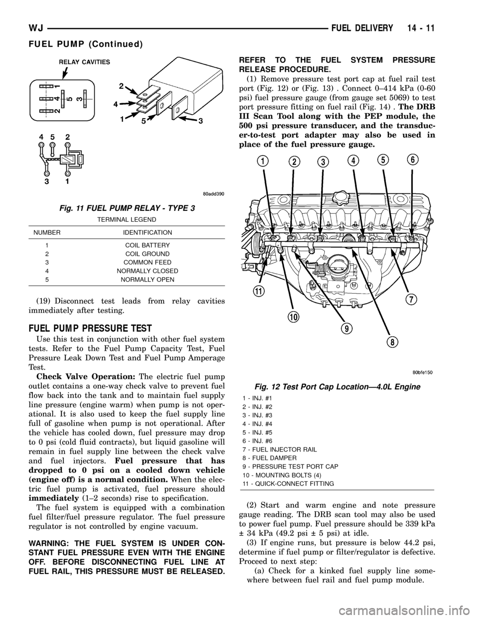
(1) Remove pressure test port cap at fuel rail test
port (Fig. 12) or (Fig. 13) . Connect 0±414 kPa (0-60
psi) fuel pressure gauge (from gauge set 5069) to test
port pressure fitting on fuel rail (Fig. 14) .The DRB
III Scan Tool along with the PEP module, the
500 psi pressure transducer, and the transduc-
er-to-test port adapter may also be used in
place of the fuel pressure gauge.
(2) Start and warm engine and note pressure
gauge reading. The DRB scan tool may also be used
to power fuel pump. Fuel pressure should be 339 kPa
34 kPa (49.2 psi 5 psi) at idle.
(3) If engine runs, but pressure is below 44.2 psi,
determine if fuel pump or filter/regulator is defective.
Proceed to next step:
(a) Check for a kinked fuel supply line some-
where between fuel rail and fuel pump module.
Fig. 11 FUEL PUMP RELAY - TYPE 3
TERMINAL LEGEND
NUMBER IDENTIFICATION
1 COIL BATTERY
2 COIL GROUND
3 COMMON FEED
4 NORMALLY CLOSED
5 NORMALLY OPEN
Fig. 12 Test Port Cap LocationÐ4.0L Engine
1 - INJ. #1
2 - INJ. #2
3 - INJ. #3
4 - INJ. #4
5 - INJ. #5
6 - INJ. #6
7 - FUEL INJECTOR RAIL
8 - FUEL DAMPER
9 - PRESSURE TEST PORT CAP
10 - MOUNTING BOLTS (4)
11 - QUICK-CONNECT FITTING
WJFUEL DELIVERY 14 - 11
FUEL PUMP (Continued)
Page 1910 of 2199
INSTRUMENT PANEL SYSTEM
REMOVAL
WARNING: ON VEHICLES EQUIPPED WITH AIR-
BAGS, DISABLE THE AIRBAG SYSTEM BEFORE
ATTEMPTING ANY STEERING WHEEL, STEERING
COLUMN, OR INSTRUMENT PANEL COMPONENT
DIAGNOSIS OR SERVICE. DISCONNECT AND ISO-
LATE THE BATTERY NEGATIVE (GROUND) CABLE,
THEN WAIT TWO MINUTES FOR THE AIRBAG SYS-
TEM CAPACITOR TO DISCHARGE BEFORE PER-
FORMING FURTHER DIAGNOSIS OR SERVICE. THIS
IS THE ONLY SURE WAY TO DISABLE THE AIRBAG
SYSTEM. FAILURE TO TAKE THE PROPER PRE-
CAUTIONS COULD RESULT IN ACCIDENTAL AIR-
BAG DEPLOYMENT AND POSSIBLE PERSONAL
INJURY.
NOTE: Before starting this procedure, be certain to
turn the steering wheel until the front wheels are in
the straight-ahead position.
(1) Disconnect and isolate the battery negative
cable.
(2) Remove the trim from the right and left A-pil-
lars. (Refer to 23 - BODY/INTERIOR/A-PILLAR
TRIM - REMOVAL).(3) Remove the top cover from the instrument
panel. (Refer to 23 - BODY/INSTRUMENT PANEL/
INSTRUMENT PANEL TOP COVER - REMOVAL).
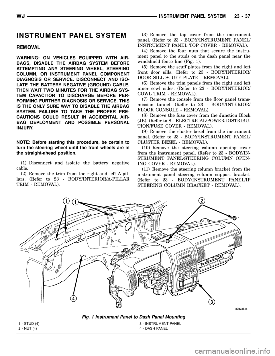
(4) Remove the four nuts that secure the instru-
ment panel to the studs on the dash panel near the
windshield fence line (Fig. 1).
(5) Remove the scuff plates from the right and left
front door sills. (Refer to 23 - BODY/INTERIOR/
DOOR SILL SCUFF PLATE - REMOVAL).
(6) Remove the trim panels from the right and left
inner cowl sides. (Refer to 23 - BODY/INTERIOR/
COWL TRIM - REMOVAL).
(7) Remove the console from the floor panel trans-
mission tunnel. (Refer to 23 - BODY/INTERIOR/
FLOOR CONSOLE - REMOVAL).
(8) Remove the fuse cover from the Junction Block
(JB). (Refer to 8 - ELECTRICAL/POWER DISTRIBU-
TION/FUSE COVER - REMOVAL).
(9) Remove the cluster bezel from the instrument
panel. (Refer to 23 - BODY/INSTRUMENT PANEL/
CLUSTER BEZEL - REMOVAL).
(10) Remove the steering column opening cover
from the instrument panel. (Refer to 23 - BODY/IN-
STRUMENT PANEL/STEERING COLUMN OPEN-
ING COVER - REMOVAL).
(11) Remove the steering column bracket from the
instrument panel steering column support bracket.
(Refer to 23 - BODY/INSTRUMENT PANEL/IP
STEERING COLUMN BRACKET - REMOVAL).
Fig. 1 Instrument Panel to Dash Panel Mounting
1 - STUD (4)
2 - NUT (4)3 - INSTRUMENT PANEL
4 - DASH PANEL
WJINSTRUMENT PANEL SYSTEM 23 - 37
Page 1912 of 2199
(18) Remove the four nuts that secure the steering
column to the studs on the instrument panel steering
column support bracket.
(19) Remove the steering column from the instru-
ment panel. Be certain that the steering wheel is
locked and secured from rotation to prevent the loss
of clockspring centering.
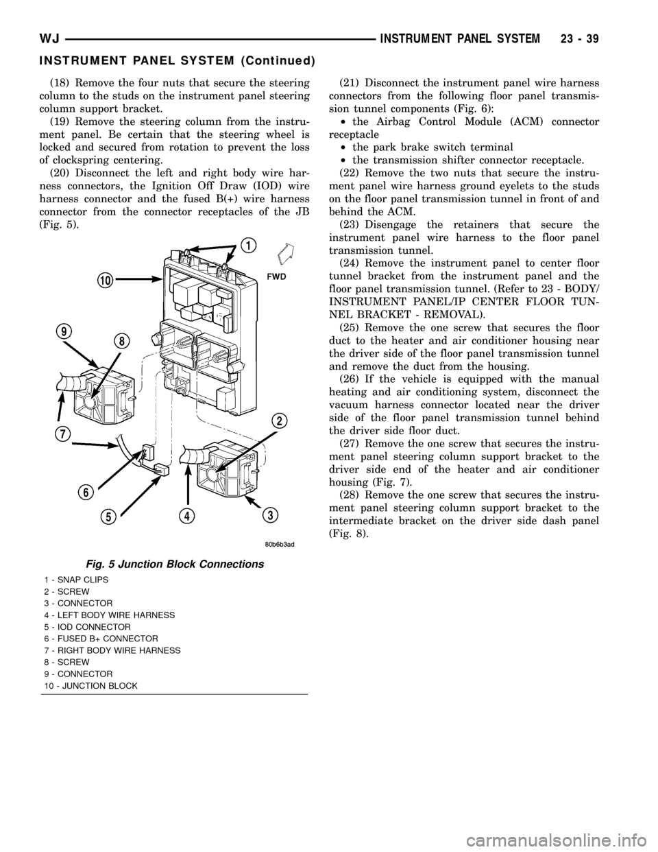
(20) Disconnect the left and right body wire har-
ness connectors, the Ignition Off Draw (IOD) wire
harness connector and the fused B(+) wire harness
connector from the connector receptacles of the JB
(Fig. 5).(21) Disconnect the instrument panel wire harness
connectors from the following floor panel transmis-
sion tunnel components (Fig. 6):
²the Airbag Control Module (ACM) connector
receptacle
²the park brake switch terminal
²the transmission shifter connector receptacle.
(22) Remove the two nuts that secure the instru-
ment panel wire harness ground eyelets to the studs
on the floor panel transmission tunnel in front of and
behind the ACM.
(23) Disengage the retainers that secure the
instrument panel wire harness to the floor panel
transmission tunnel.
(24) Remove the instrument panel to center floor
tunnel bracket from the instrument panel and the
floor panel transmission tunnel. (Refer to 23 - BODY/
INSTRUMENT PANEL/IP CENTER FLOOR TUN-
NEL BRACKET - REMOVAL).
(25) Remove the one screw that secures the floor
duct to the heater and air conditioner housing near
the driver side of the floor panel transmission tunnel
and remove the duct from the housing.
(26) If the vehicle is equipped with the manual
heating and air conditioning system, disconnect the
vacuum harness connector located near the driver
side of the floor panel transmission tunnel behind
the driver side floor duct.
(27) Remove the one screw that secures the instru-
ment panel steering column support bracket to the
driver side end of the heater and air conditioner
housing (Fig. 7).
(28) Remove the one screw that secures the instru-
ment panel steering column support bracket to the
intermediate bracket on the driver side dash panel
(Fig. 8).
Fig. 5 Junction Block Connections
1 - SNAP CLIPS
2 - SCREW
3 - CONNECTOR
4 - LEFT BODY WIRE HARNESS
5 - IOD CONNECTOR
6 - FUSED B+ CONNECTOR
7 - RIGHT BODY WIRE HARNESS
8 - SCREW
9 - CONNECTOR
10 - JUNCTION BLOCK
WJINSTRUMENT PANEL SYSTEM 23 - 39
INSTRUMENT PANEL SYSTEM (Continued)
Page 1914 of 2199
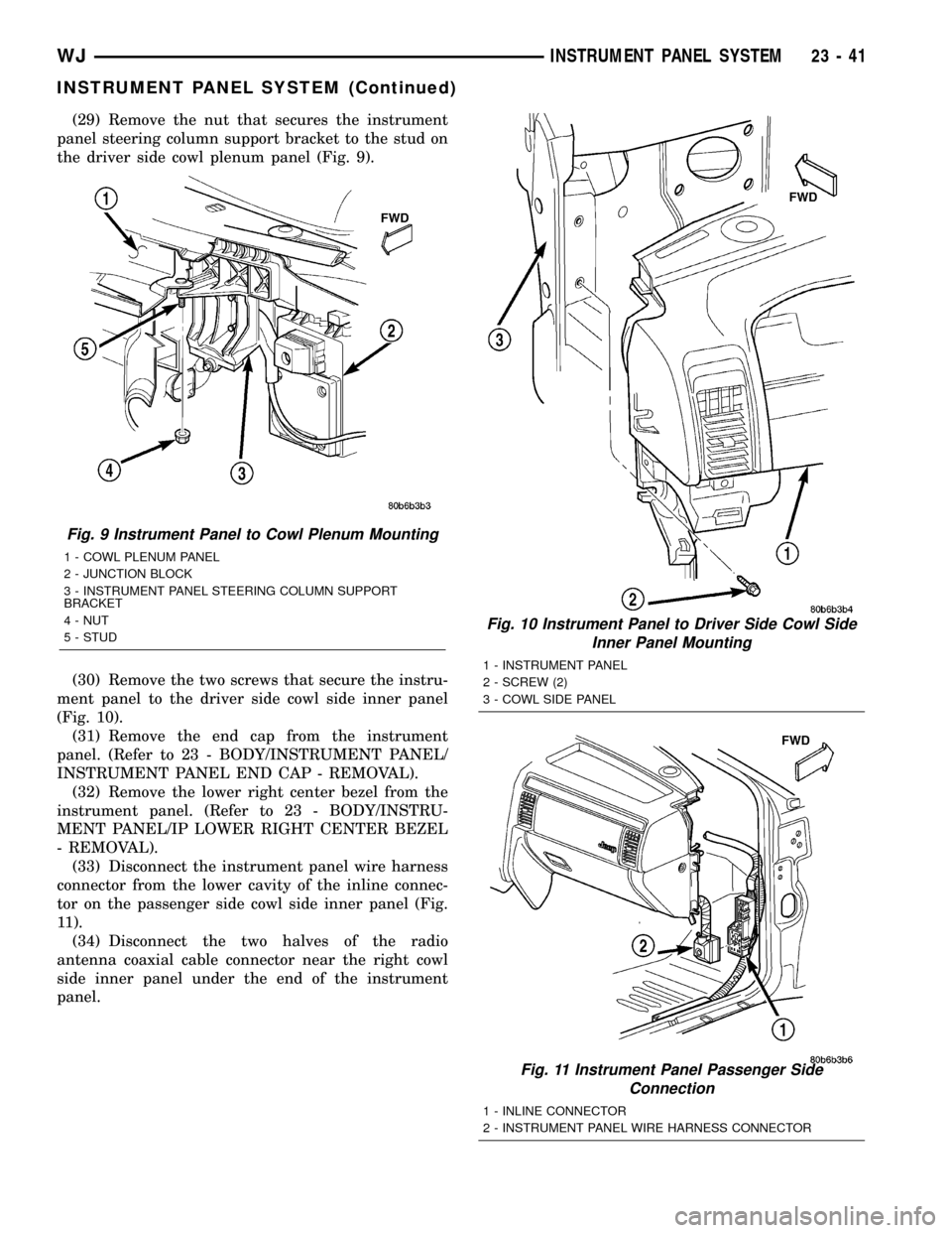
(29) Remove the nut that secures the instrument
panel steering column support bracket to the stud on
the driver side cowl plenum panel (Fig. 9).
(30) Remove the two screws that secure the instru-
ment panel to the driver side cowl side inner panel
(Fig. 10).
(31) Remove the end cap from the instrument
panel. (Refer to 23 - BODY/INSTRUMENT PANEL/
INSTRUMENT PANEL END CAP - REMOVAL).
(32) Remove the lower right center bezel from the
instrument panel. (Refer to 23 - BODY/INSTRU-
MENT PANEL/IP LOWER RIGHT CENTER BEZEL
- REMOVAL).
(33) Disconnect the instrument panel wire harness
connector from the lower cavity of the inline connec-
tor on the passenger side cowl side inner panel (Fig.
11).
(34) Disconnect the two halves of the radio
antenna coaxial cable connector near the right cowl
side inner panel under the end of the instrument
panel.
Fig. 9 Instrument Panel to Cowl Plenum Mounting
1 - COWL PLENUM PANEL
2 - JUNCTION BLOCK
3 - INSTRUMENT PANEL STEERING COLUMN SUPPORT
BRACKET
4 - NUT
5 - STUD
Fig. 10 Instrument Panel to Driver Side Cowl Side
Inner Panel Mounting
1 - INSTRUMENT PANEL
2 - SCREW (2)
3 - COWL SIDE PANEL
Fig. 11 Instrument Panel Passenger Side
Connection
1 - INLINE CONNECTOR
2 - INSTRUMENT PANEL WIRE HARNESS CONNECTOR
WJINSTRUMENT PANEL SYSTEM 23 - 41
INSTRUMENT PANEL SYSTEM (Continued)
Page 1917 of 2199
(23) Reconnect the instrument panel wire harness
connectors to the following floor panel transmission
tunnel components:
²the Airbag Control Module (ACM) connector
receptacle
²the park brake switch terminal
²the transmission shifter connector receptacle.
(24) Reconnect the left and right body wire har-
ness connectors, the Ignition Off Draw (IOD) wire
harness connector and the fused B(+) wire harness
connector to the connector receptacles of the Junction
Block (JB) and tighten the connector screws (Fig. 5).
Tighten the screws to 4 N´m (36 in. lbs.).
(25) Engage the lower steering column shaft with
the steering shaft coupler and position the steering
column to the mounting studs on the instrument
panel steering column support bracket (Fig. 4).
(26) Install and tighten the four nuts that secure
the steering column to the studs on the instrument
panel steering column support bracket. Tighten the
nuts to 11.8 N´m (105 in. lbs.).
(27) Install and tighten the bolt that secures the
coupler to the lower steering column shaft. Tighten
the bolt to 49 N´m (36 ft. lbs.).
(28) Turn the ignition switch to the On position,
then install the shifter interlock cable connector into
the ignition lock housing receptacle.
(29) Reconnect the instrument panel wire harness
connectors to the following steering column compo-
nents (Fig. 3):
²the two lower clockspring connector receptacles
²the left multi-function switch connector recepta-
cle
²the right multi-function switch connector recep-
tacle
²the two ignition switch connector receptacles
²the shifter interlock solenoid connector recepta-
cle
²if the vehicle is so equipped, the Sentry Key
Immobilizer Module (SKIM) connector receptacle.
(30) Position the lower tilting steering column
shroud to the steering column multi-function switchmounting housing, then install and tighten the screw
that secures the shroud to the housing (Fig. 2).
Tighten the screw to 1.9 N´m (17 in. lbs.).
(31) Position the upper tilting steering column
shroud over the steering column. Align the upper and
lower shrouds with each other and snap the two
halves together.
(32) Reinstall the steering column bracket onto the
instrument panel steering column support bracket.
(Refer to 23 - BODY/INSTRUMENT PANEL/IP
STEERING COLUMN BRACKET - INSTALLA-
TION).
(33) Reinstall the steering column opening cover
onto the instrument panel. (Refer to 23 - BODY/IN-
STRUMENT PANEL/STEERING COLUMN OPEN-
ING COVER - INSTALLATION).
(34) Reinstall the cluster bezel onto the instru-
ment panel. (Refer to 23 - BODY/INSTRUMENT
PANEL/CLUSTER BEZEL - INSTALLATION).
(35) Reinstall the fuse cover onto the Junction
Block (JB). (Refer to 8 - ELECTRICAL/POWER DIS-
TRIBUTION/FUSE COVER - INSTALLATION).
(36) Reinstall the console onto the floor panel
transmission tunnel. (Refer to 23 - BODY/INTERI-
OR/FLOOR CONSOLE - INSTALLATION).
(37) Reinstall the trim panels onto the right and
left inner cowl sides. (Refer to 23 - BODY/INTERI-
OR/COWL TRIM - INSTALLATION).
(38) Reinstall the scuff plates onto the right and
left front door sills. (Refer to 23 - BODY/INTERIOR/
DOOR SILL SCUFF PLATE - INSTALLATION).
(39) Reinstall the top cover onto the instrument
panel. (Refer to 23 - BODY/INSTRUMENT PANEL/
INSTRUMENT PANEL TOP COVER - INSTALLA-
TION).
(40) Reinstall the trim onto the right and left
A-pillars. (Refer to 23 - BODY/INTERIOR/A-PILLAR
TRIM - INSTALLATION).
(41) Reconnect the battery negative cable.
23 - 44 INSTRUMENT PANEL SYSTEMWJ
INSTRUMENT PANEL SYSTEM (Continued)