2002 JEEP GRAND CHEROKEE Indicator
[x] Cancel search: IndicatorPage 607 of 2199

OPERATION
The Vehicle Theft Security System (VTSS) indica-
tor gives a visible indication of the VTSS arming sta-
tus. One side of Light-Emittiong Diode (LED) in the
VTSS indicator is connected to unswitched battery
current through a fused B(+) circuit and a fuse in the
Junction Block (JB). The other side of the LED is
hard wired to the Body Control Module (BCM), which
controls the operation of the VTSS indicator by pull-
ing this side of the LED circuit to ground. When the
VTSS arming is in progress, the BCM will flash the
LED rapidly on and off for about fifteen seconds.
When the VTSS has been successfully armed, the
BCM will flash the LED on and off continually at a
much slower rate until the VTSS has been disarmed.
The VTSS indicator can be diagnosed using conven-
tional diagnostic tools and methods.
DIAGNOSIS AND TESTING - VTSS INDICATOR
The diagnosis found here addresses an inoperative
Vehicle Theft Security System (VTSS) indicator con-
dition. If the problem being diagnosed is related to
indicator accuracy, be certain to confirm that the
problem is with the indicator and not with an inop-
erative VTSS. (Refer to 8 - ELECTRICAL/VEHICLE
THEFT SECURITY - DIAGNOSIS AND TESTING -
VEHICLE THEFT SECURITY SYSTEM). If no VTSS
problem is found, the following procedure will help to
locate a short or open in the VTSS indicator control
circuit. Refer to the appropriate wiring information.
WARNING: ON VEHICLES EQUIPPED WITH AIR-
BAGS, DISABLE THE AIRBAG SYSTEM BEFORE
ATTEMPTING ANY STEERING WHEEL, STEERING
COLUMN, OR INSTRUMENT PANEL COMPONENT
DIAGNOSIS OR SERVICE. DISCONNECT AND ISO-
LATE THE BATTERY NEGATIVE (GROUND) CABLE,
THEN WAIT TWO MINUTES FOR THE AIRBAG SYS-
TEM CAPACITOR TO DISCHARGE BEFORE PER-
FORMING FURTHER DIAGNOSIS OR SERVICE. THIS
IS THE ONLY SURE WAY TO DISABLE THE AIRBAG
SYSTEM. FAILURE TO TAKE THE PROPER PRE-CAUTIONS COULD RESULT IN ACCIDENTAL AIR-
BAG DEPLOYMENT AND POSSIBLE PERSONAL
INJURY.
(1) Check the fused B(+) fuse in the Junction
Block (JB). If OK, go to Step 2. If not OK, repair the
shorted circuit or component and replace the faulty
fuse.
(2) Check for battery voltage at the fused B(+) fuse
in the JB. If OK, go to Step 3. If not OK, repair the
open fused B(+) circuit between the JB and the
Power Distribution Center (PDC).
(3) Disconnect and isolate the battery negative
cable. Disconnect the instrument panel wire harness
connector for the automatic headlamp light sensor/
VTSS indicator from the automatic headlamp light
sensor/VTSS indicator pigtail wire connector. Recon-
nect the battery negative cable. Check for battery
voltage at the fused B(+) circuit cavity of the instru-
ment panel wire harness connector for the automatic
headlamp light sensor/VTSS indicator. If OK, go to
Step 4. If not OK, repair the open fused B(+) circuit
between the VTSS indicator and the JB.
(4) Disconnect and isolate the battery negative
cable. Disconnect the instrument panel wire harness
connector for the JB from the JB connector recepta-
cle. Check for continuity between the VTSS indicator
driver circuit cavity of the instrument panel wire
harness connector for the automatic headlamp light
sensor/VTSS indicator and a good ground. There
should be no continuity. If OK, go to Step 5. If not
OK, repair the shorted VTSS indicator driver circuit
between the VTSS indicator and the JB.
(5) Check for continuity between the VTSS indica-
tor driver circuit of the instrument panel wire har-
ness connector for the automatic headlamp light
sensor/VTSS indicator and the instrument panel wire
harness connector for the JB. There should be conti-
nuity. If OK, replace the faulty VTSS indicator. If not
OK, repair the open VTSS indicator driver circuit
between the VTSS indicator and the JB.
8Q - 16 VEHICLE THEFT SECURITYWJ
VTSS INDICATOR (Continued)
Page 632 of 2199

switch mounting housing. Tighten the screws to 2.5
N´m (22 in. lbs.).
(3) Reconnect the instrument panel wire harness
connector for the right multi-function switch to the
switch connector receptacle.
(4) Position the lower tilting steering column
shroud to the underside of the steering column (Fig.
18).
(5) Install and tighten the screw that secures the
lower tilting steering column shroud to the multi-
function switch mounting housing. Tighten the screw
to 1.9 N´m (17 in. lbs.).
(6) Position the upper tilting column shroud over
the steering column with the hazard warning switch
button inserted through the hole in the upper surface
of the shroud. Align the upper tilting steering column
shroud to the lower shroud and snap the two shroud
halves together.
(7) Reconnect the battery negative cable.
WASHER FLUID LEVEL
SWITCH
DESCRIPTION
The washer fluid level switch is a single pole, sin-
gle throw reed-type switch mounted near the front of
the washer reservoir, forward of the two washer
pump/motors (Fig. 20). Only the molded plastic
switch mounting flange and connector receptacle are
visible when the switch is installed in the reservoir.A short nipple formation extends from the inner sur-
face of the switch mounting flange, and a barb on the
nipple near the switch mounting flange is press-fit
into a rubber grommet seal installed in the mounting
hole of the reservoir. A small plastic float pivots on
the end of a bracket that extends from the switch
nipple formation. Within the float is a small magnet,
which actuates the reed switch. The washer fluid
level switch cannot be adjusted or repaired. If faulty
or damaged, the switch must be replaced.
OPERATION
The washer fluid level switch uses a pivoting,
oblong float to monitor the level of the washer fluid
in the washer reservoir. The float contains a small
magnet. When the float pivots, the changing proxim-
ity of its magnetic field will cause the contacts of the
small, stationary reed switch to open or close. When
the fluid level in the washer reservoir is at or above
the float level, the float moves to a vertical position
and the switch contacts open. When the fluid level in
the washer reservoir falls below the pivoting float,
the float moves to a horizontal position and the
switch contacts close. The switch is connected to the
vehicle electrical system through a dedicated take
out and connector of the left headlamp and dash wire
harness. The switch receives a five volt reference sig-
nal from the Body Control Module (BCM) through
the washer fluid switch output circuit. The switch is
grounded at all times through another take out of
the left headlamp and dash wire harness with a sin-
gle eyelet terminal connector that is secured under a
ground screw near the top of the left front fender
inner shield in the engine compartment.
When the switch closes, the BCM senses the volt-
age change on the circuit. The BCM is programmed
to send low washer fluid messages to the Electronic
Vehicle Information Center (EVIC) over the Program-
mable Communications Interface (PCI) data bus. The
EVIC is programmed to respond to this message by
displaying the Washer Fluid Low warning and send-
ing a chime request message back to the BCM over
the PCI data bus. Then the BCM generates an audi-
ble chime tone warning. A resistor within the washer
fluid level switch allows the BCM to monitor and
diagnose this circuit. The BCM will store a Diagnos-
tic Trouble Code (DTC) for any fault that it detects.
For retrieval of this fault information and further
diagnosis of the washer fluid level switch, the BCM,
the EVIC, the PCI data bus, the BCM message out-
puts to the EVIC that control the Low Washer Fluid
indicator, or the EVIC message outputs to the BCM
that control chime service, a DRBIIItscan tool and
the appropriate diagnostic information are required.
Fig. 20 Washer Fluid Level Switch (Viewed from
Bottom of Reservoir)
1 - REAR WASHER PUMP/MOTOR
2 - FRONT WASHER PUMP/MOTOR
3 - WASHER FLUID LEVEL SWITCH
WJFRONT WIPERS/WASHERS 8R - 25
RIGHT MULTI-FUNCTION SWITCH (Continued)
Page 673 of 2199

Component Page
Power Outlet......................... 8W-41
Power Seats.......................... 8W-63
Power Windows....................... 8W-60
Powertrain Control Module.............. 8W-30
Radio............................... 8W-47
Rain Sensor.......................... 8W-49
Recirculation Door Motor/Actuator........ 8W-42
Red Brake Warning Indicator Switch....... 8W-35
Remote Keyless Module................. 8W-39
Remote Radio Switches................. 8W-47
Splices.............................. 8W-10
Seat Belt Switch...................... 8W-43
Seat Module.......................... 8W-63
Sentry Key Immobilizer Module.......... 8W-39
Shifter Assembly...................... 8W-31
Side Impact Sensors................... 8W-43
Side Marker Lamps.................... 8W-50
Side Repeater Lamps................... 8W-52
Siren............................... 8W-49
Speakers............................ 8W-47Component Page
Speed Control Switches................. 8W-33
Sunroof............................. 8W-64
Temperature Valve Actuator............. 8W-42
Throttle Position Sensor................ 8W-30
Trailer Tow.......................... 8W-54
Transfer Case Position Sensor............ 8W-31
Transmission......................... 8W-31
Turn Signal Lamps.................... 8W-52
Underhood Lamp...................... 8W-44
Vehicle Information Center.............. 8W-49
Viscous/Cabin Heater................... 8W-30
Visor/Vanity Lamps.................... 8W-44
Washer Fluid Level Switch.............. 8W-53
Wastegate Solenoid.................... 8W-30
Water In Fuel Sensor................... 8W-30
Wheel Speed Sensors................... 8W-35
Window Defogger...................... 8W-48
Wiper High/Low Relay.................. 8W-53
Wiper Motor.......................... 8W-53
Washer Pump......................... 8W-5
8W - 02 - 2 8W-02 COMPONENT INDEXWJ
Page 858 of 2199

8W-35 ANTILOCK BRAKES
Component Page
Brake Lamp Switch.................. 8W-35-5
Controller Antilock Brake...... 8W-35-2, 3, 4, 5, 6
Diagnostic Junction Port............. 8W-35-2, 3
Engine Control Module.............. 8W-35-4, 5
Fuse 4........................... 8W-35-2, 3
Fuse 19.......................... 8W-35-2, 3
Fuse 23............................ 8W-35-5
Fuse 25.......................... 8W-35-2, 3
G107............................ 8W-35-2, 3Component Page
Junction Block.................. 8W-35-2, 3, 5
Left Front Wheel Speed Sensor......... 8W-35-6
Left Rear Wheel Speed Sensor.......... 8W-35-6
Power Distribution Center........... 8W-35-2, 3
Powertrain Control Module............. 8W-35-4
Red Brake Warning Indicator Switch..... 8W-35-5
Right Front Wheel Speed Sensor........ 8W-35-6
Right Rear Wheel Speed Sensor......... 8W-35-6
WJ8W-35 ANTILOCK BRAKES 8W - 35 - 1
Page 1051 of 2199

Component Page
LIFTGATE FLIP-UP PUSH
BUTTON SWITCH................ 8W-80-97
LIFTGATE FLIP-UP RELEASE
SOLENOID...................... 8W-80-97
LIFTGATE POWER LOCK MOTOR..... 8W-80-97
LINE PRESSURE SENSOR (4.7L)...... 8W-80-98
MANIFOLD ABSOLUTE PRESSURE
SENSOR (4.0L)................... 8W-80-98
MANIFOLD ABSOLUTE PRESSURE
SENSOR (4.7L)................... 8W-80-98
MANUAL TEMPERATURE
CONTROL C1 (MTC).............. 8W-80-98
MANUAL TEMPERATURE
CONTROL C2 (MTC).............. 8W-80-99
MASS AIR FLOW SENSOR (DIESEL) . . . 8W-80-99
MODE DOOR MOTOR/ACTUATOR
(AZC).......................... 8W-80-99
NEEDLE MOVEMENT SENSOR
(DIESEL)....................... 8W-80-99
OUTPUT SPEED SENSOR (4.0L)...... 8W-80-99
OUTPUT SPEED SENSOR (4.7L)..... 8W-80-100
OVERHEAD MAP/COURTESY LAMP . . 8W-80-100
OXYGEN SENSOR 1/1 UPSTREAM.... 8W-80-100
OXYGEN SENSOR 1/2 DOWNSTREAM . 8W-80-100
OXYGEN SENSOR 2/1 UPSTREAM.... 8W-80-100
OXYGEN SENSOR 2/2
DOWNSTREAM................. 8W-80-101
PARK/NEUTRAL POSITION SWITCH
(4.0L).......................... 8W-80-101
PARK/NEUTRAL POSITION SWITCH
(DIESEL)...................... 8W-80-101
PASSENGER AIRBAG.............. 8W-80-101
PASSENGER BLEND DOOR
MOTOR/ACTUATOR (LHD) (AZC) . . . 8W-80-101
PASSENGER BLEND DOOR
MOTOR/ACTUATOR (RHD) (AZC) . . . 8W-80-102
PASSENGER CURTAIN AIRBAG...... 8W-80-102
PASSENGER DOOR LOCK MOTOR/AJAR
SWITCH....................... 8W-80-102
PASSENGER DOOR MODULE C1..... 8W-80-102
PASSENGER DOOR MODULE C2..... 8W-80-103
PASSENGER FRONT DOOR
COURTESY LAMP............... 8W-80-103
PASSENGER FRONT POWER
WINDOW MOTOR............... 8W-80-103
PASSENGER HEATED SEAT BACK
(PREMIUM I/III)................. 8W-80-103
PASSENGER HEATED SEAT CUSHION
(PREMIUM I/III)................. 8W-80-104
PASSENGER HEATED SEAT SWITCH . 8W-80-104
PASSENGER LUMBAR MOTOR
(MIDLINE/PREMIUM)............ 8W-80-104
PASSENGER LUMBAR SWITCH
(MIDLINE/PREMIUM)............ 8W-80-104
PASSENGER POWER MIRROR....... 8W-80-105Component Page
PASSENGER POWER SEAT FRONT
RISER MOTOR.................. 8W-80-105
PASSENGER POWER SEAT
HORIZONTAL MOTOR........... 8W-80-105
PASSENGER POWER SEAT REAR
RISER MOTOR.................. 8W-80-105
PASSENGER POWER SEAT RECLINER
MOTOR (MIDLINE/PREMIUM)..... 8W-80-106
PASSENGER POWER SEAT SWITCH
(MIDLINE/PREMIUM)............ 8W-80-106
PASSENGER REAR POWER
WINDOW MOTOR............... 8W-80-106
PASSENGER REAR POWER
WINDOW SWITCH............... 8W-80-106
PASSENGER SEAT BELT SWITCH.... 8W-80-106
PASSENGER SIDE IMPACT
SENSOR....................... 8W-80-107
POWER AMPLIFIER C1
(PREMIUM RADIO).............. 8W-80-107
POWER AMPLIFIER C2
(PREMIUM RADIO).............. 8W-80-107
POWER CONNECTOR.............. 8W-80-108
POWERTRAIN CONTROL
MODULE C1 (GAS).............. 8W-80-108
POWERTRAIN CONTROL
MODULE C2 (GAS).............. 8W-80-109
POWERTRAIN CONTROL
MODULE C3 (GAS).............. 8W-80-110
RADIATOR FAN MOTOR............ 8W-80-110
RADIATOR FAN RELAY............. 8W-80-111
RADIO C1........................ 8W-80-111
RADIO C2........................ 8W-80-111
RAIN SENSOR (AUTOWIPE)......... 8W-80-112
REAR POWER OUTLET............. 8W-80-112
REAR WASHER PUMP.............. 8W-80-112
REAR WIPER MOTOR.............. 8W-80-112
RECIRCULATION DOOR
MOTOR/ACTUATOR (AZC)......... 8W-80-112
RED BRAKE WARNING INDICATOR
SWITCH....................... 8W-80-113
REMOTE KEYLESS MODULE
(JAPAN)....................... 8W-80-113
RIGHT COURTESY LAMP........... 8W-80-113
RIGHT DOOR HANDLE
COURTESY LAMP............... 8W-80-113
RIGHT FOG LAMP................. 8W-80-113
RIGHT FRONT DOOR SPEAKER..... 8W-80-114
RIGHT FRONT IMPACT SENSOR..... 8W-80-114
RIGHT FRONT PARK LAMP......... 8W-80-114
RIGHT FRONT PARK/TURN SIGNAL LAMP
(EXCEPT BUILT-UP-EXPORT)...... 8W-80-114
RIGHT FRONT SIDE MARKER LAMP
(EXCEPT BUILT-UP-EXPORT)...... 8W-80-115
RIGHT FRONT TURN SIGNAL LAMP
(BUILT-UP-EXPORT)............. 8W-80-115
8W - 80 - 4 8W-80 CONNECTOR PIN-OUTWJ
Page 1056 of 2199

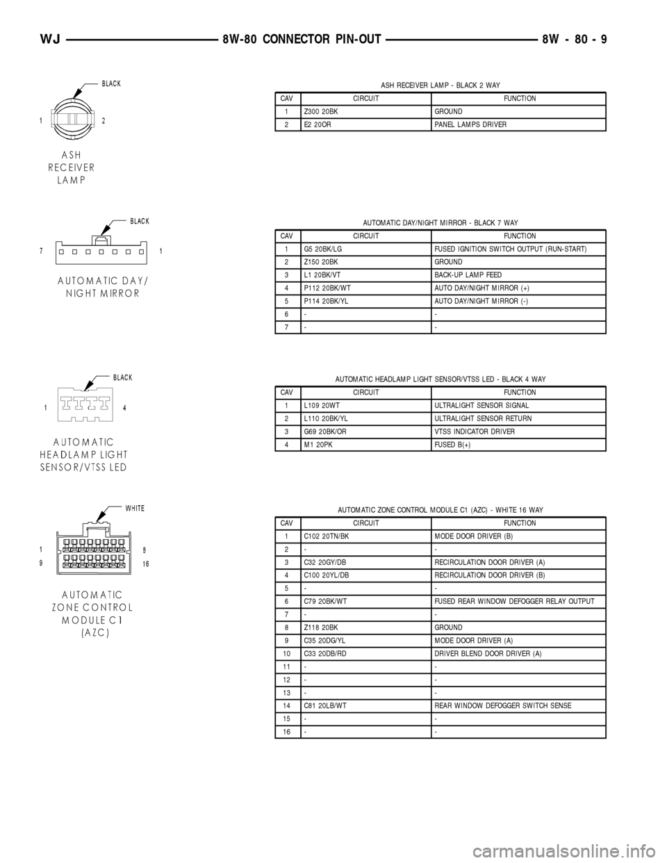
ASH RECEIVER LAMP - BLACK 2 WAY
CAV CIRCUIT FUNCTION
1 Z300 20BK GROUND
2 E2 20OR PANEL LAMPS DRIVER
AUTOMATIC DAY/NIGHT MIRROR - BLACK 7 WAY
CAV CIRCUIT FUNCTION
1 G5 20BK/LG FUSED IGNITION SWITCH OUTPUT (RUN-START)
2 Z150 20BK GROUND
3 L1 20BK/VT BACK-UP LAMP FEED
4 P112 20BK/WT AUTO DAY/NIGHT MIRROR (+)
5 P114 20BK/YL AUTO DAY/NIGHT MIRROR (-)
6- -
7- -
AUTOMATIC HEADLAMP LIGHT SENSOR/VTSS LED - BLACK 4 WAY
CAV CIRCUIT FUNCTION
1 L109 20WT ULTRALIGHT SENSOR SIGNAL
2 L110 20BK/YL ULTRALIGHT SENSOR RETURN
3 G69 20BK/OR VTSS INDICATOR DRIVER
4 M1 20PK FUSED B(+)
AUTOMATIC ZONE CONTROL MODULE C1 (AZC) - WHITE 16 WAY
CAV CIRCUIT FUNCTION
1 C102 20TN/BK MODE DOOR DRIVER (B)
2- -
3 C32 20GY/DB RECIRCULATION DOOR DRIVER (A)
4 C100 20YL/DB RECIRCULATION DOOR DRIVER (B)
5- -
6 C79 20BK/WT FUSED REAR WINDOW DEFOGGER RELAY OUTPUT
7- -
8 Z118 20BK GROUND
9 C35 20DG/YL MODE DOOR DRIVER (A)
10 C33 20DB/RD DRIVER BLEND DOOR DRIVER (A)
11 - -
12 - -
13 - -
14 C81 20LB/WT REAR WINDOW DEFOGGER SWITCH SENSE
15 - -
16 - -
WJ8W-80 CONNECTOR PIN-OUT 8W - 80 - 9
Page 1058 of 2199

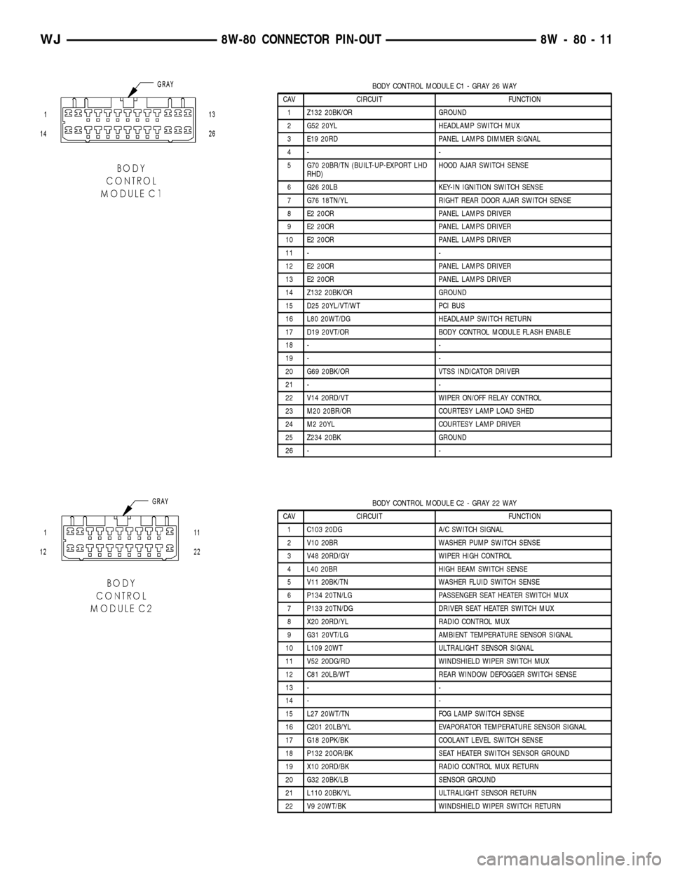
BODY CONTROL MODULE C1 - GRAY 26 WAY
CAV CIRCUIT FUNCTION
1 Z132 20BK/OR GROUND
2 G52 20YL HEADLAMP SWITCH MUX
3 E19 20RD PANEL LAMPS DIMMER SIGNAL
4- -
5 G70 20BR/TN (BUILT-UP-EXPORT LHD
RHD)HOOD AJAR SWITCH SENSE
6 G26 20LB KEY-IN IGNITION SWITCH SENSE
7 G76 18TN/YL RIGHT REAR DOOR AJAR SWITCH SENSE
8 E2 20OR PANEL LAMPS DRIVER
9 E2 20OR PANEL LAMPS DRIVER
10 E2 20OR PANEL LAMPS DRIVER
11 - -
12 E2 20OR PANEL LAMPS DRIVER
13 E2 20OR PANEL LAMPS DRIVER
14 Z132 20BK/OR GROUND
15 D25 20YL/VT/WT PCI BUS
16 L80 20WT/DG HEADLAMP SWITCH RETURN
17 D19 20VT/OR BODY CONTROL MODULE FLASH ENABLE
18 - -
19 - -
20 G69 20BK/OR VTSS INDICATOR DRIVER
21 - -
22 V14 20RD/VT WIPER ON/OFF RELAY CONTROL
23 M20 20BR/OR COURTESY LAMP LOAD SHED
24 M2 20YL COURTESY LAMP DRIVER
25 Z234 20BK GROUND
26 - -
BODY CONTROL MODULE C2 - GRAY 22 WAY
CAV CIRCUIT FUNCTION
1 C103 20DG A/C SWITCH SIGNAL
2 V10 20BR WASHER PUMP SWITCH SENSE
3 V48 20RD/GY WIPER HIGH CONTROL
4 L40 20BR HIGH BEAM SWITCH SENSE
5 V11 20BK/TN WASHER FLUID SWITCH SENSE
6 P134 20TN/LG PASSENGER SEAT HEATER SWITCH MUX
7 P133 20TN/DG DRIVER SEAT HEATER SWITCH MUX
8 X20 20RD/YL RADIO CONTROL MUX
9 G31 20VT/LG AMBIENT TEMPERATURE SENSOR SIGNAL
10 L109 20WT ULTRALIGHT SENSOR SIGNAL
11 V52 20DG/RD WINDSHIELD WIPER SWITCH MUX
12 C81 20LB/WT REAR WINDOW DEFOGGER SWITCH SENSE
13 - -
14 - -
15 L27 20WT/TN FOG LAMP SWITCH SENSE
16 C201 20LB/YL EVAPORATOR TEMPERATURE SENSOR SIGNAL
17 G18 20PK/BK COOLANT LEVEL SWITCH SENSE
18 P132 20OR/BK SEAT HEATER SWITCH SENSOR GROUND
19 X10 20RD/BK RADIO CONTROL MUX RETURN
20 G32 20BK/LB SENSOR GROUND
21 L110 20BK/YL ULTRALIGHT SENSOR RETURN
22 V9 20WT/BK WINDSHIELD WIPER SWITCH RETURN
WJ8W-80 CONNECTOR PIN-OUT 8W - 80 - 11
Page 1116 of 2199

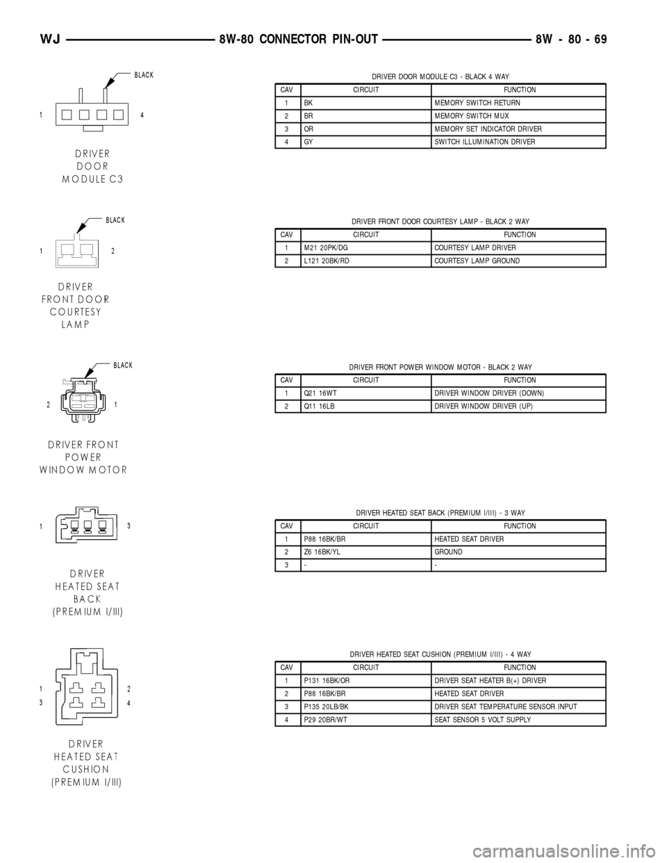
DRIVER DOOR MODULE C3 - BLACK 4 WAY
CAV CIRCUIT FUNCTION
1 BK MEMORY SWITCH RETURN
2 BR MEMORY SWITCH MUX
3 OR MEMORY SET INDICATOR DRIVER
4 GY SWITCH ILLUMINATION DRIVER
DRIVER FRONT DOOR COURTESY LAMP - BLACK 2 WAY
CAV CIRCUIT FUNCTION
1 M21 20PK/DG COURTESY LAMP DRIVER
2 L121 20BK/RD COURTESY LAMP GROUND
DRIVER FRONT POWER WINDOW MOTOR - BLACK 2 WAY
CAV CIRCUIT FUNCTION
1 Q21 16WT DRIVER WINDOW DRIVER (DOWN)
2 Q11 16LB DRIVER WINDOW DRIVER (UP)
DRIVER HEATED SEAT BACK (PREMIUM I/III)-3WAY
CAV CIRCUIT FUNCTION
1 P88 16BK/BR HEATED SEAT DRIVER
2 Z6 16BK/YL GROUND
3- -
DRIVER HEATED SEAT CUSHION (PREMIUM I/III)-4WAY
CAV CIRCUIT FUNCTION
1 P131 16BK/OR DRIVER SEAT HEATER B(+) DRIVER
2 P88 16BK/BR HEATED SEAT DRIVER
3 P135 20LB/BK DRIVER SEAT TEMPERATURE SENSOR INPUT
4 P29 20BR/WT SEAT SENSOR 5 VOLT SUPPLY
WJ8W-80 CONNECTOR PIN-OUT 8W - 80 - 69