2002 JEEP GRAND CHEROKEE battery location
[x] Cancel search: battery locationPage 1429 of 2199

(5) Connect (-) and (+) test cable leads into LCS
adapter receptacles. Use10 amp (10A +)receptacle
and common (-) receptacles.
(6) Gain access to MAIN MENU on DRB screen.
(7) Press DVOM button on DRB.
(8) Using left/right arrow keys, highlight CHAN-
NEL 1 function on DRB screen.
(9) Press ENTER three times.
(10) Using up/down arrow keys, highlight RANGE
on DRB screen (screen will default to 2 amp scale).
(11) Press ENTER to change 2 amp scale to 10
amp scale.This step must be done to prevent
damage to DRB scan tool or LCS adapter
(blown fuse).
(12) Remove cover from Power Distribution Center
(PDC).
(13) Remove fuel pump relay from PDC. Refer to
label on PDC cover for relay location.
WARNING: BEFORE PROCEEDING TO NEXT STEP,
NOTE THE FUEL PUMP WILL BE ACTIVATED AND
SYSTEM PRESSURE WILL BE PRESENT. THIS WILL
OCCUR AFTER CONNECTING TEST LEADS FROM
LCS ADAPTER INTO FUEL PUMP RELAY CAVITIES.
THE FUEL PUMP WILL OPERATE EVEN WITH IGNI-
TION KEY IN OFF POSITION. BEFORE ATTACHING
TEST LEADS, BE SURE ALL FUEL LINES AND
FUEL SYSTEM COMPONENTS ARE CONNECTED.
CAUTION: To prevent possible damage to the vehi-
cle electrical system and LCS adapter, the test
leads must be connected into relay cavities exactly
as shown in following steps.
Depending upon vehicle model, year or engine con-
figuration, three different types of relays may be
used: Type-1, type-2 and type±3.
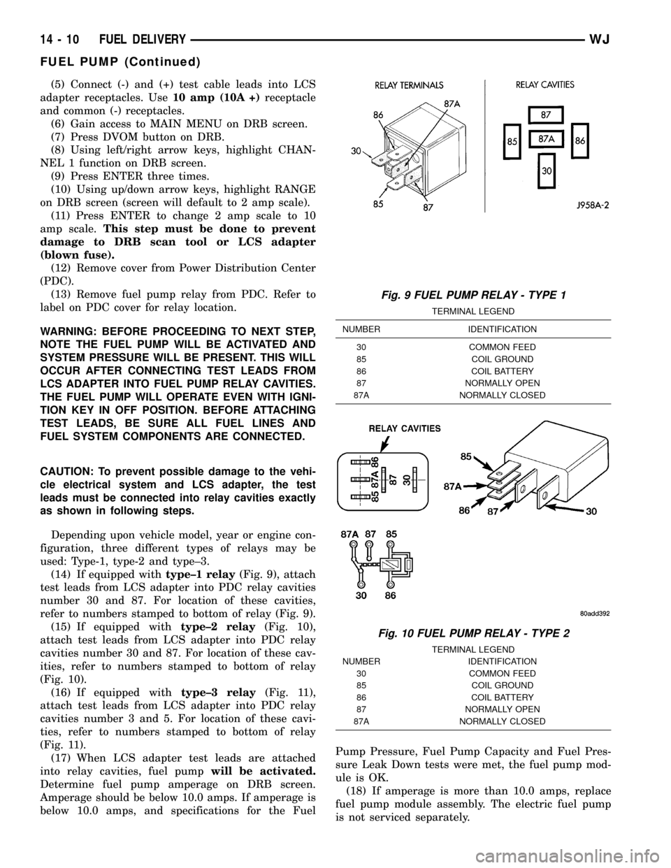
(14) If equipped withtype±1 relay(Fig. 9), attach
test leads from LCS adapter into PDC relay cavities
number 30 and 87. For location of these cavities,
refer to numbers stamped to bottom of relay (Fig. 9).
(15) If equipped withtype±2 relay(Fig. 10),
attach test leads from LCS adapter into PDC relay
cavities number 30 and 87. For location of these cav-
ities, refer to numbers stamped to bottom of relay
(Fig. 10).
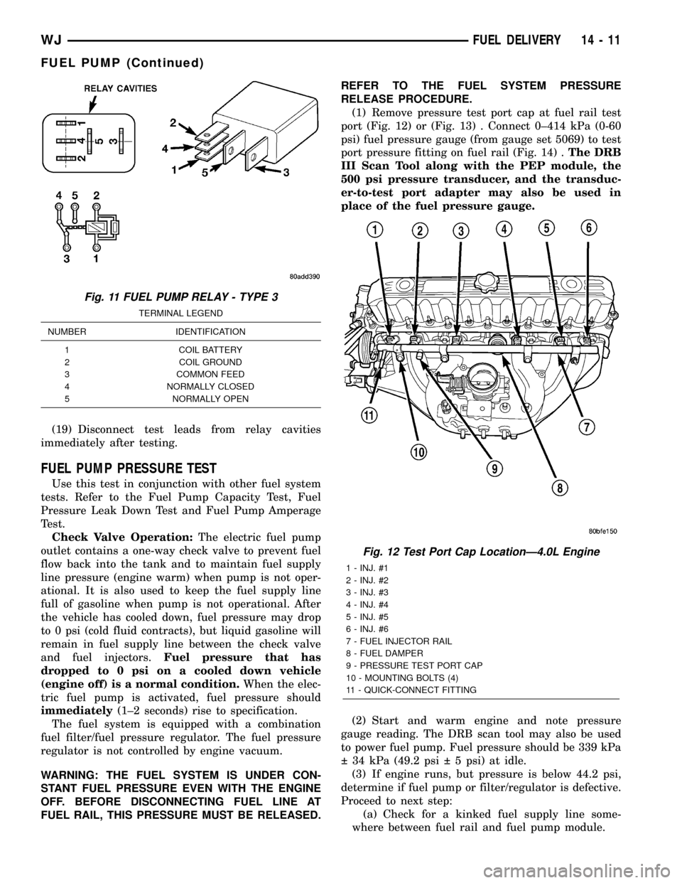
(16) If equipped withtype±3 relay(Fig. 11),
attach test leads from LCS adapter into PDC relay
cavities number 3 and 5. For location of these cavi-
ties, refer to numbers stamped to bottom of relay
(Fig. 11).
(17) When LCS adapter test leads are attached
into relay cavities, fuel pumpwill be activated.
Determine fuel pump amperage on DRB screen.
Amperage should be below 10.0 amps. If amperage is
below 10.0 amps, and specifications for the FuelPump Pressure, Fuel Pump Capacity and Fuel Pres-
sure Leak Down tests were met, the fuel pump mod-
ule is OK.
(18) If amperage is more than 10.0 amps, replace
fuel pump module assembly. The electric fuel pump
is not serviced separately.
Fig. 9 FUEL PUMP RELAY - TYPE 1
TERMINAL LEGEND
NUMBER IDENTIFICATION
30 COMMON FEED
85 COIL GROUND
86 COIL BATTERY
87 NORMALLY OPEN
87A NORMALLY CLOSED
Fig. 10 FUEL PUMP RELAY - TYPE 2
TERMINAL LEGEND
NUMBER IDENTIFICATION
30 COMMON FEED
85 COIL GROUND
86 COIL BATTERY
87 NORMALLY OPEN
87A NORMALLY CLOSED
14 - 10 FUEL DELIVERYWJ
FUEL PUMP (Continued)
Page 1430 of 2199

(19) Disconnect test leads from relay cavities
immediately after testing.
FUEL PUMP PRESSURE TEST
Use this test in conjunction with other fuel system
tests. Refer to the Fuel Pump Capacity Test, Fuel
Pressure Leak Down Test and Fuel Pump Amperage
Test.
Check Valve Operation:The electric fuel pump
outlet contains a one-way check valve to prevent fuel
flow back into the tank and to maintain fuel supply
line pressure (engine warm) when pump is not oper-
ational. It is also used to keep the fuel supply line
full of gasoline when pump is not operational. After
the vehicle has cooled down, fuel pressure may drop
to 0 psi (cold fluid contracts), but liquid gasoline will
remain in fuel supply line between the check valve
and fuel injectors.Fuel pressure that has
dropped to 0 psi on a cooled down vehicle
(engine off) is a normal condition.When the elec-
tric fuel pump is activated, fuel pressure should
immediately(1±2 seconds) rise to specification.
The fuel system is equipped with a combination
fuel filter/fuel pressure regulator. The fuel pressure
regulator is not controlled by engine vacuum.
WARNING: THE FUEL SYSTEM IS UNDER CON-
STANT FUEL PRESSURE EVEN WITH THE ENGINE
OFF. BEFORE DISCONNECTING FUEL LINE AT
FUEL RAIL, THIS PRESSURE MUST BE RELEASED.REFER TO THE FUEL SYSTEM PRESSURE
RELEASE PROCEDURE.
(1) Remove pressure test port cap at fuel rail test
port (Fig. 12) or (Fig. 13) . Connect 0±414 kPa (0-60
psi) fuel pressure gauge (from gauge set 5069) to test
port pressure fitting on fuel rail (Fig. 14) .The DRB
III Scan Tool along with the PEP module, the
500 psi pressure transducer, and the transduc-
er-to-test port adapter may also be used in
place of the fuel pressure gauge.
(2) Start and warm engine and note pressure
gauge reading. The DRB scan tool may also be used
to power fuel pump. Fuel pressure should be 339 kPa
34 kPa (49.2 psi 5 psi) at idle.
(3) If engine runs, but pressure is below 44.2 psi,
determine if fuel pump or filter/regulator is defective.
Proceed to next step:
(a) Check for a kinked fuel supply line some-
where between fuel rail and fuel pump module.
Fig. 11 FUEL PUMP RELAY - TYPE 3
TERMINAL LEGEND
NUMBER IDENTIFICATION
1 COIL BATTERY
2 COIL GROUND
3 COMMON FEED
4 NORMALLY CLOSED
5 NORMALLY OPEN
Fig. 12 Test Port Cap LocationÐ4.0L Engine
1 - INJ. #1
2 - INJ. #2
3 - INJ. #3
4 - INJ. #4
5 - INJ. #5
6 - INJ. #6
7 - FUEL INJECTOR RAIL
8 - FUEL DAMPER
9 - PRESSURE TEST PORT CAP
10 - MOUNTING BOLTS (4)
11 - QUICK-CONNECT FITTING
WJFUEL DELIVERY 14 - 11
FUEL PUMP (Continued)
Page 1435 of 2199

CAUTION: The left and right fuel rails are replaced
as an assembly. Do not attempt to separate rail
halves at connector tube (Fig. 22). Due to design of
tube, it does not use any clamps. Never attempt to
install a clamping device of any kind to tube. When
removing fuel rail assembly for any reason, be care-
ful not to bend or kink tube.
(1) Remove fuel tank filler tube cap.
(2) Perform Fuel System Pressure Release Proce-
dure.
(3) Remove negative battery cable at battery.
(4) Remove air duct at throttle body air box.
(5) Remove air box at throttle body.
(6) Remove wiring at rear of generator.
(7) Disconnect fuel line latch clip and fuel line at
fuel rail. A special tool will be necessary for fuel line
disconnection. Refer to Quick-Connect Fittings.
(8) Remove vacuum lines at throttle body.(9) Disconnect electrical connectors at all 8 fuel
injectors. To remove connector refer to (Fig. 23). Push
red colored slider away from injector (1). While push-
ing slider, depress tab (2) and remove connector (3)
from injector. The factory fuel injection wiring har-
ness is numerically tagged (INJ 1, INJ 2, etc.) for
injector position identification. If harness is not
tagged, note wiring location before removal.
(10) Disconnect electrical connectors at throttle
body.
(11) Disconnect electrical connectors at MAP and
IAT sensors.
Fig. 21 Fuel Injector Rail/Fuel DamperÐ4.0L Engine
1 - INJ. #1
2 - INJ. #2
3 - INJ. #3
4 - INJ. #4
5 - INJ. #5
6 - INJ. #6
7 - FUEL INJECTOR RAIL
8 - FUEL DAMPER
9 - PRESSURE TEST PORT CAP
10 - MOUNTING BOLTS (4)
11 - QUICK-CONNECT FITTING
Fig. 22 FUEL INJECTOR RAIL - 4.7L V-8 EN
1 - MOUNTING BOLTS (4)
2 - INJ.#7
3 - INJ.#5
4 - QUICK-CONNECT FITTING
5 - INJ.#3
6 - FUEL INJECTOR RAIL
7 - INJ.#1
8 - CONNECTOR TUBE
9 - INJ.#2
10 - INJ.#4
11 - INJ.#6
12 - INJ.#8
13 - PRESSURE TEST PORT CAP
14 - 16 FUEL DELIVERYWJ
FUEL RAIL (Continued)
Page 1436 of 2199

(12) Remove first three ignition coils on each bank
(cylinders #1, 3, 5, 2, 4 and 6). Refer to Ignition Coil
Removal/Installation.
(13) Remove 4 fuel rail mounting bolts (Fig. 22).
(14) Gently rock and pullleftside of fuel rail until
fuel injectors just start to clear machined holes in
cylinder head. Gently rock and pullrightside of rail
until injectors just start to clear cylinder head holes.
Repeat this procedure (left/right) until all injectors
have cleared cylinder head holes.
(15) Remove fuel rail (with injectors attached)
from engine.
(16) If fuel injectors are to be removed, refer to
Fuel Injector Removal/Installation.
REMOVAL - 4.0L
The fuel damper is not serviced separately.
WARNING: THE FUEL SYSTEM IS UNDER CON-
STANT FUEL PRESSURE EVEN WITH ENGINE OFF.
THIS PRESSURE MUST BE RELEASED BEFORE
SERVICING FUEL RAIL.
(1) Remove fuel tank filler tube cap.
(2) Perform Fuel System Pressure Release Proce-
dure.
(3) Disconnect negative battery cable from battery.(4) Remove air tube at top of throttle body. Note:
Some engine/vehicles may require removal of air
cleaner ducts at throttle body.
(5) Disconnect electrical connectors at all 6 fuel
injectors. To remove connector refer to (Fig. 25). Push
red colored slider away from injector (1). While push-
ing slider, depress tab (2) and remove connector (3)
from injector. The factory fuel injection wiring har-
ness is numerically tagged (INJ 1, INJ 2, etc.) for
injector position identification. If harness is not
tagged, note wiring location before removal.
(6) Remove oxygen sensor wiring clip nuts at fuel
rail mounting studs (certain emissions packages
only).
(7) Disconnect fuel supply line latch clip and fuel
line at fuel rail. Refer to Quick-Connect Fittings.
(8) Disconnect throttle cable at throttle body. Refer
to Throttle Cable Removal/Installation.
Fig. 23 Remove/Install Injector ConnectorÐ4.7L V-8
Engine
Fig. 24 Fuel Rail MountingÐ4.0L Engine
1 - INJ. #1
2 - INJ. #2
3 - INJ. #3
4 - INJ. #4
5 - INJ. #5
6 - INJ. #6
7 - FUEL INJECTOR RAIL
8 - FUEL DAMPER
9 - PRESSURE TEST PORT CAP
10 - MOUNTING BOLTS (4)
11 - QUICK-CONNECT FITTING
WJFUEL DELIVERY 14 - 17
FUEL RAIL (Continued)
Page 1451 of 2199

FUEL INJECTION
DIAGNOSIS AND TESTING
VISUAL INSPECTION
A visual inspection for loose, disconnected or incor-
rectly routed wires, vacuum lines and hoses should
be made. This should be done before attempting to
diagnose or service the fuel injection system. A visual
check will help spot these faults and save unneces-
sary test and diagnostic time. A thorough visual
inspection will include the following checks:
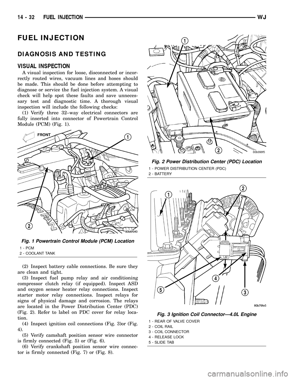
(1) Verify three 32±way electrical connectors are
fully inserted into connector of Powertrain Control
Module (PCM) (Fig. 1).
(2) Inspect battery cable connections. Be sure they
are clean and tight.
(3) Inspect fuel pump relay and air conditioning
compressor clutch relay (if equipped). Inspect ASD
and oxygen sensor heater relay connections. Inspect
starter motor relay connections. Inspect relays for
signs of physical damage and corrosion. The relays
are located in the Power Distribution Center (PDC)
(Fig. 2). Refer to label on PDC cover for relay loca-
tion.
(4) Inspect ignition coil connections (Fig. 3)or (Fig.
4).
(5) Verify camshaft position sensor wire connector
is firmly connected (Fig. 5) or (Fig. 6).
(6) Verify crankshaft position sensor wire connec-
tor is firmly connected (Fig. 7) or (Fig. 8).
Fig. 1 Powertrain Control Module (PCM) Location
1 - PCM
2 - COOLANT TANK
Fig. 2 Power Distribution Center (PDC) Location
1 - POWER DISTRIBUTION CENTER (PDC)
2 - BATTERY
Fig. 3 Ignition Coil ConnectorÐ4.0L Engine
1 - REAR OF VALVE COVER
2 - COIL RAIL
3 - COIL CONNECTOR
4 - RELEASE LOCK
5 - SLIDE TAB
14 - 32 FUEL INJECTIONWJ
Page 1457 of 2199

(23) Inspect for pinched or leaking fuel tubes/lines.
Inspect for pinched, cracked or leaking fuel hoses.
(24) Inspect for exhaust system restrictions such
as pinched exhaust pipes, collapsed muffler or
plugged catalytic convertor.
(25) If equipped with automatic transmission, ver-
ify electrical harness is firmly connected to park/neu-
tral switch and to transmission components.
(26) Verify fuel pump module pigtail harness elec-
trical connector (Fig. 15) is firmly connected to body
harness connector.
(27) Inspect fuel line harness (from fuel pump
module) at fuel filter/fuel pressure regulator (Fig. 15)
for chaffing, cracks or leaks.
(28) Verify battery cable and solenoid feed wire
connections to starter solenoid are tight and clean.
(29) Inspect for chaffed wires or wires rubbing up
against other components.
(30) Inspect for chaffed vacuum lines or lines rub-
bing up against other components.
Fig. 15 Fuel Filter/Fuel Pressure Regulator Location
1 - FUEL RETURN LINE
2 - FUEL SUPPLY LINE (TO FUEL RAIL)
3 - FUEL FILTER/FUEL PRESSURE REGULATOR
4 - FUEL PRESSURE LINE
5 - REAR AXLE
6 - ELEC. CONNECTOR
7 - EVAP LINE
14 - 38 FUEL INJECTIONWJ
FUEL INJECTION (Continued)
Page 1463 of 2199

The PCM determines injector on-time (pulse width)
based on various inputs.
DIAGNOSIS AND TESTING - FUEL INJECTOR
To perform a complete test of the fuel injectors and
their circuitry, use the DRB scan tool and refer to the
appropriate Powertrain Diagnostics Procedures man-
ual. To test the injector only, refer to the following:
Disconnect the fuel injector wire harness connector
from the injector. The injector is equipped with 2
electrical terminals (pins). Place an ohmmeter across
the terminals. Resistance reading should be approxi-
mately 12 ohms 1.2 ohms at 20ÉC (68ÉF).
REMOVAL
WARNING: THE FUEL SYSTEM IS UNDER CON-
STANT PRESSURE EVEN WITH ENGINE OFF.
BEFORE SERVICING FUEL INJECTOR(S), FUEL
SYSTEM PRESSURE MUST BE RELEASED.
To remove one or more fuel injectors, the fuel rail
assembly must be removed from engine.
(1) Perform Fuel System Pressure Release Proce-
dure.
(2) Remove fuel injector rail. Refer to Fuel Injector
Rail Removal/Installation.
(3) Remove clip(s) retaining injector(s) to fuel rail
(Fig. 25).
(4) Remove injector(s) from fuel rail.
INSTALLATION
(1) Apply a small amount of engine oil to each fuel
injector o-ring. This will help in fuel rail installation.
(2) Install injector(s) and injector clip(s) to fuel
rail.
(3) Install fuel rail assembly. Refer to Fuel Injector
Rail Removal/Installation.
(4) Start engine and check for leaks.
FUEL PUMP RELAY
DESCRIPTION
The 5±pin, 12±volt, fuel pump relay is located in
the Power Distribution Center (PDC). Refer to the
label on the PDC cover for relay location.
OPERATION
The Powertrain Control Module (PCM) energizes
the electric fuel pump through the fuel pump relay.
The fuel pump relay is energized by first applying
battery voltage to it when the ignition key is turned
ON, and then applying a ground signal to the relay
from the PCM.
Whenever the ignition key is turned ON, the elec-
tric fuel pump will operate. But, the PCM will shut-
down the ground circuit to the fuel pump relay in
approximately 1±3 seconds unless the engine is oper-
ating or the starter motor is engaged.
IDLE AIR CONTROL MOTOR
DESCRIPTION
The IAC stepper motor is mounted to the throttle
body, and regulates the amount of air bypassing the
control of the throttle plate. As engine loads and
ambient temperatures change, engine rpm changes.
A pintle on the IAC stepper motor protrudes into a
passage in the throttle body, controlling air flow
through the passage. The IAC is controlled by the
Powertrain Control Module (PCM) to maintain the
target engine idle speed.
OPERATION
At idle, engine speed can be increased by retract-
ing the IAC motor pintle and allowing more air to
pass through the port, or it can be decreased by
restricting the passage with the pintle and diminish-
ing the amount of air bypassing the throttle plate.
The IAC is called a stepper motor because it is
moved (rotated) in steps, or increments. Opening the
IAC opens an air passage around the throttle blade
which increases RPM.Fig. 25 Fuel Injector MountingÐTypical (4.7L V-8
Engine Shown)
1 - INLET FITTING
2 - FUEL INJECTOR RAIL
3 - CLIP
4 - FUEL INJECTOR
14 - 44 FUEL INJECTIONWJ
FUEL INJECTOR (Continued)
Page 1871 of 2199

TIRE PRESSURE MONITORING
DESCRIPTION
The EVIC will monitor the tire pressure signals
from the five tire sensors and determine if any tire
has gone below the low pressure threshold or raised
above the high pressure threshold. Refer to the table
below.
LOW TIRE PRESSURE THRESHOLDS
SYSTEM STATUS
INDICATORTIRE PRESSURE
ON 179 kPa (26 PSI)
OFF 214 kPa (31 PSI)
HIGH TIRE PRESSURE THRESHOLDS
SYSTEM STATUS
INDICATORTIRE PRESSURE
ON 310 kPa (45 PSI)
OFF 276 kPa (40 PSI)
The Remote Tire Pressure Monitors (RTPM) are
not internally serviceable. For a Sensor Failure or
Low Battery fault, the RTPM must be replaced.
OPERATION
If equipped with the Tire Pressure Monitoring Sys-
tem, each of the vehicle's five wheels will have a
valve stem with a pressure sensor and radio trans-
mitter built in. Signals from the tire pressure sensors
are received and interpreted by the Electronic Vehi-
cle Information Center (EVIC). A sensor in a
mounted wheel will broadcast its detected pressure
once per minute when the vehicle is moving faster
than 40 km/h (25 mph). The spare tire sensor will
broadcast once every hour. Each sensor's broadcast is
uniquely coded so that the EVIC can determine loca-
tion. The individual tire pressures can be displayed
graphically on the EVIC
DIAGNOSIS AND TESTING - TIRE PRESSURE
MONITORING SYSTEM
All Tire Pressure Monitoring System Faults are
specific to one location. If a9BATTERY LOW9or
9SENSOR FAILURE9fault is detected, the location
will be displayed. The appropriate sensor/transmitter
can then be replaced. If a single sensor/transmitter
cannot be detected by the EVIC, replace that sensor
transmitter. If none of the sensors/transmitters can
be detected, refer to symptoms in the EVIC section.
For additional system description and diagnosis,
refer to Tire Pressure Monitoring in the Body Diag-
nostic manual.
SENSOR
REMOVAL - TIRE PRESSURE SENSOR/
TRANSMITTER
(1) Remove the tire/wheel from the vehicle.
CAUTION: When removing the stick on balancing
weights from the wheel, do not use an abrasive
cleaner or a cleaner which will damage the protec-
tive finish on the wheel.
(2) Remove the balancing weights from the wheel.
NOTE: The cap used on this valve stem contains an
O-ring seal to prevent contamination and moisture
from entering the valve stem. Retain this valve stem
cap for re-use. Do not substitute a regular valve
stem cap in its place.
(3) Remove the cap from the valve stem.
NOTE: The valve stem used on this vehicle is made
of aluminum and the core is nickel plated brass.
The original valve stem core must be reinstalled
and not substituted for a valve stem core made of a
different material. This is required to prevent corro-
sion in the valve stem caused by the different met-
als.
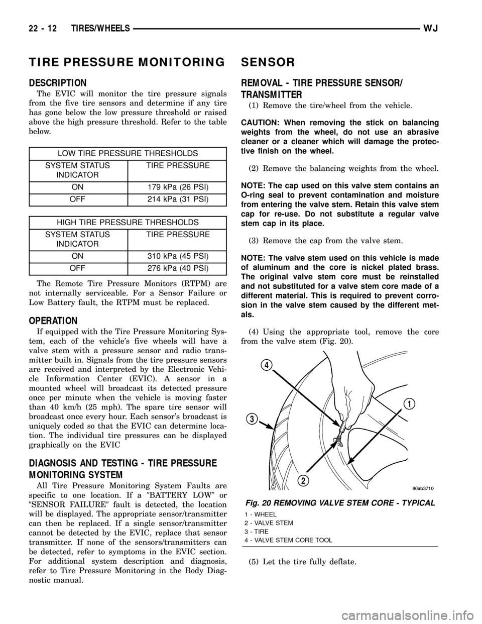
(4) Using the appropriate tool, remove the core
from the valve stem (Fig. 20).
(5) Let the tire fully deflate.
Fig. 20 REMOVING VALVE STEM CORE - TYPICAL
1 - WHEEL
2 - VALVE STEM
3 - TIRE
4 - VALVE STEM CORE TOOL
22 - 12 TIRES/WHEELSWJ