2002 JEEP GRAND CHEROKEE rear light
[x] Cancel search: rear lightPage 1134 of 2199
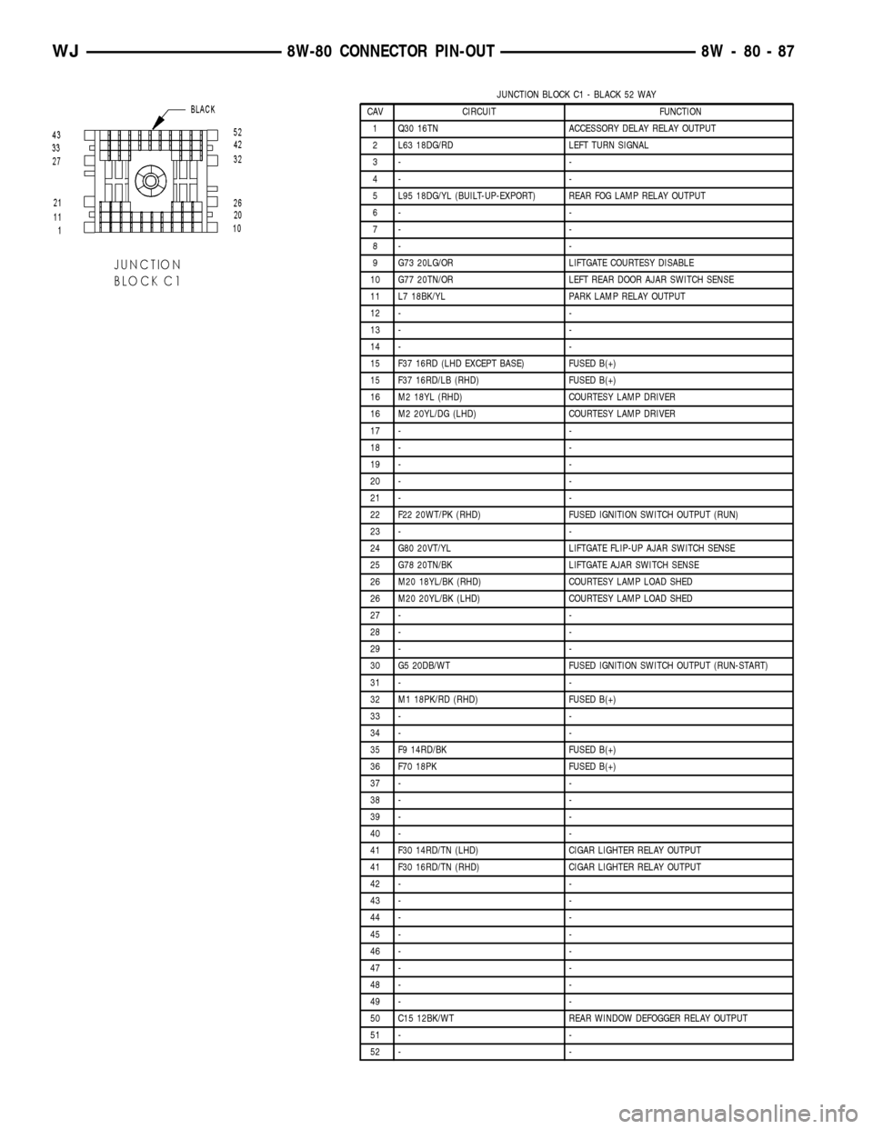
JUNCTION BLOCK C1 - BLACK 52 WAY
CAV CIRCUIT FUNCTION
1 Q30 16TN ACCESSORY DELAY RELAY OUTPUT
2 L63 18DG/RD LEFT TURN SIGNAL
3- -
4- -
5 L95 18DG/YL (BUILT-UP-EXPORT) REAR FOG LAMP RELAY OUTPUT
6- -
7- -
8- -
9 G73 20LG/OR LIFTGATE COURTESY DISABLE
10 G77 20TN/OR LEFT REAR DOOR AJAR SWITCH SENSE
11 L7 18BK/YL PARK LAMP RELAY OUTPUT
12 - -
13 - -
14 - -
15 F37 16RD (LHD EXCEPT BASE) FUSED B(+)
15 F37 16RD/LB (RHD) FUSED B(+)
16 M2 18YL (RHD) COURTESY LAMP DRIVER
16 M2 20YL/DG (LHD) COURTESY LAMP DRIVER
17 - -
18 - -
19 - -
20 - -
21 - -
22 F22 20WT/PK (RHD) FUSED IGNITION SWITCH OUTPUT (RUN)
23 - -
24 G80 20VT/YL LIFTGATE FLIP-UP AJAR SWITCH SENSE
25 G78 20TN/BK LIFTGATE AJAR SWITCH SENSE
26 M20 18YL/BK (RHD) COURTESY LAMP LOAD SHED
26 M20 20YL/BK (LHD) COURTESY LAMP LOAD SHED
27 - -
28 - -
29 - -
30 G5 20DB/WT FUSED IGNITION SWITCH OUTPUT (RUN-START)
31 - -
32 M1 18PK/RD (RHD) FUSED B(+)
33 - -
34 - -
35 F9 14RD/BK FUSED B(+)
36 F70 18PK FUSED B(+)
37 - -
38 - -
39 - -
40 - -
41 F30 14RD/TN (LHD) CIGAR LIGHTER RELAY OUTPUT
41 F30 16RD/TN (RHD) CIGAR LIGHTER RELAY OUTPUT
42 - -
43 - -
44 - -
45 - -
46 - -
47 - -
48 - -
49 - -
50 C15 12BK/WT REAR WINDOW DEFOGGER RELAY OUTPUT
51 - -
52 - -
WJ8W-80 CONNECTOR PIN-OUT 8W - 80 - 87
Page 1137 of 2199
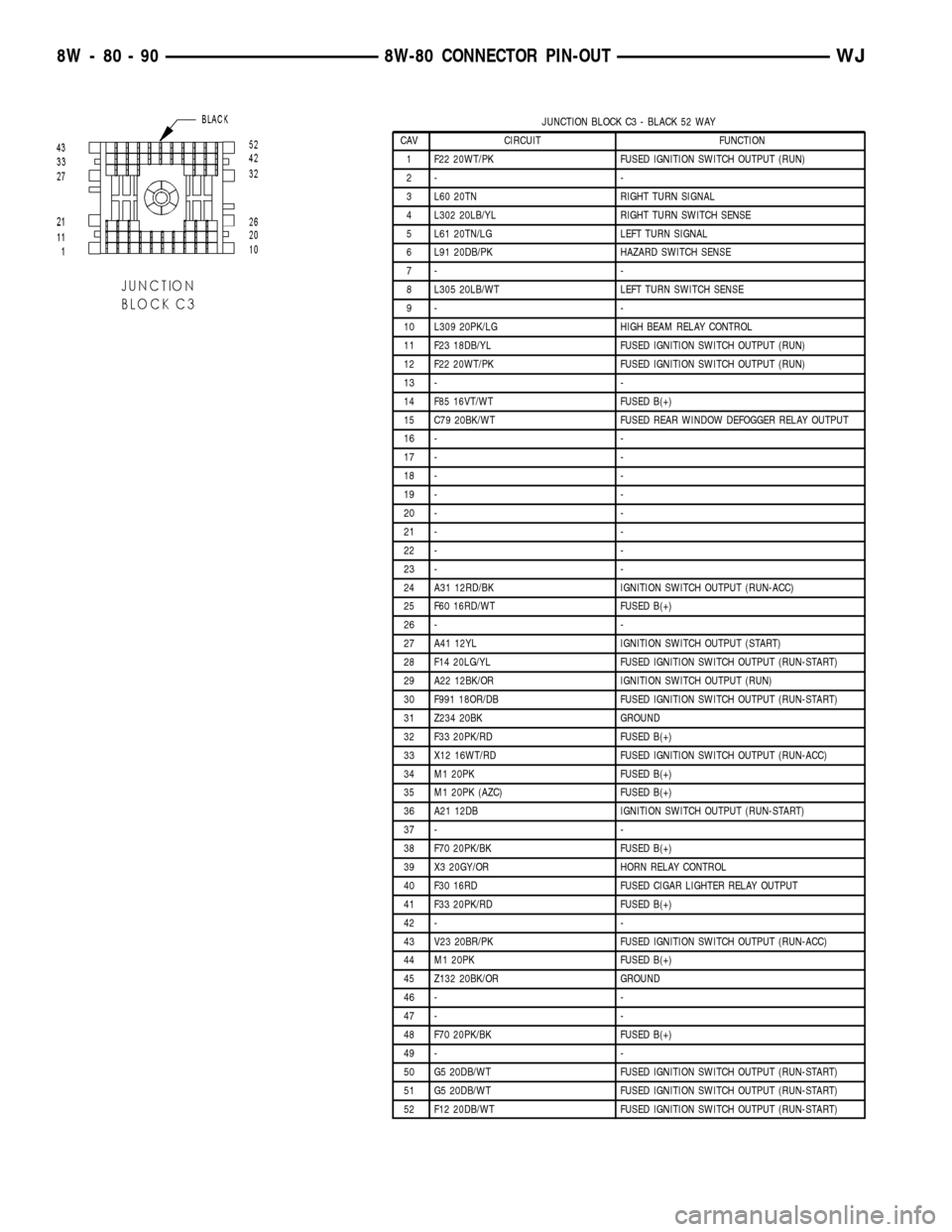
JUNCTION BLOCK C3 - BLACK 52 WAY
CAV CIRCUIT FUNCTION
1 F22 20WT/PK FUSED IGNITION SWITCH OUTPUT (RUN)
2- -
3 L60 20TN RIGHT TURN SIGNAL
4 L302 20LB/YL RIGHT TURN SWITCH SENSE
5 L61 20TN/LG LEFT TURN SIGNAL
6 L91 20DB/PK HAZARD SWITCH SENSE
7- -
8 L305 20LB/WT LEFT TURN SWITCH SENSE
9- -
10 L309 20PK/LG HIGH BEAM RELAY CONTROL
11 F23 18DB/YL FUSED IGNITION SWITCH OUTPUT (RUN)
12 F22 20WT/PK FUSED IGNITION SWITCH OUTPUT (RUN)
13 - -
14 F85 16VT/WT FUSED B(+)
15 C79 20BK/WT FUSED REAR WINDOW DEFOGGER RELAY OUTPUT
16 - -
17 - -
18 - -
19 - -
20 - -
21 - -
22 - -
23 - -
24 A31 12RD/BK IGNITION SWITCH OUTPUT (RUN-ACC)
25 F60 16RD/WT FUSED B(+)
26 - -
27 A41 12YL IGNITION SWITCH OUTPUT (START)
28 F14 20LG/YL FUSED IGNITION SWITCH OUTPUT (RUN-START)
29 A22 12BK/OR IGNITION SWITCH OUTPUT (RUN)
30 F991 18OR/DB FUSED IGNITION SWITCH OUTPUT (RUN-START)
31 Z234 20BK GROUND
32 F33 20PK/RD FUSED B(+)
33 X12 16WT/RD FUSED IGNITION SWITCH OUTPUT (RUN-ACC)
34 M1 20PK FUSED B(+)
35 M1 20PK (AZC) FUSED B(+)
36 A21 12DB IGNITION SWITCH OUTPUT (RUN-START)
37 - -
38 F70 20PK/BK FUSED B(+)
39 X3 20GY/OR HORN RELAY CONTROL
40 F30 16RD FUSED CIGAR LIGHTER RELAY OUTPUT
41 F33 20PK/RD FUSED B(+)
42 - -
43 V23 20BR/PK FUSED IGNITION SWITCH OUTPUT (RUN-ACC)
44 M1 20PK FUSED B(+)
45 Z132 20BK/OR GROUND
46 - -
47 - -
48 F70 20PK/BK FUSED B(+)
49 - -
50 G5 20DB/WT FUSED IGNITION SWITCH OUTPUT (RUN-START)
51 G5 20DB/WT FUSED IGNITION SWITCH OUTPUT (RUN-START)
52 F12 20DB/WT FUSED IGNITION SWITCH OUTPUT (RUN-START)
8W - 80 - 90 8W-80 CONNECTOR PIN-OUTWJ
Page 1176 of 2199
8W-91 CONNECTOR/GROUND/SPLICE LOCATION
TABLE OF CONTENTS
page
CONNECTOR/GROUND/SPLICE LOCATION
DESCRIPTION..........................1
CONNECTOR/GROUND/SPLICE
LOCATION
DESCRIPTION
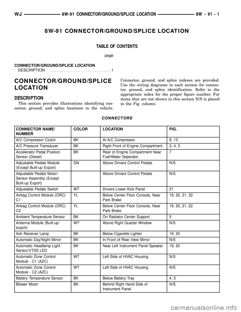
This section provides illustrations identifying con-
nector, ground, and splice locations in the vehicle.Connector, ground, and splice indexes are provided.
Use the wiring diagrams in each section for connec-
tor, ground, and splice identification. Refer to the
appropriate index for the proper figure number. For
items that are not shown in this section N/S is placed
in the Fig. column.
CONNECTORS
CONNECTOR NAME/
NUMBERCOLOR LOCATION FIG.
A/C Compressor Clutch BK At A/C Compressor 9, 13
A/C Pressure Transducer BK Right Front of Engine Compartment 3, 4, 5
Accelerator Pedal Position
Sensor (Diesel)BK Rear of Engine Compartment Near
Fuel/Water Seperator7
Adjustable Pedals Module
(Except Built-up Export)GN Above Drivers Control Pedals N/S
Adjustable Pedals Motor/
Sensor Assembly (Except
Built-up Export)Above Drivers Control Pedals N/S
Adjustable Pedals Switch WT Drivers Lower Kick Panel 21
Airbag Control Module (ORC)
C1YL Below Center Floor Console, Near
Park Brake19, 20, 21, 22
Airbag Control Module (ORC)
C2YL Below Center Floor Console, Near
Park Brake19, 20, 21, 22
Ambient Temperature Sensor BK On Radiator Center Support 5
Antenna Module (Built-up-
export)WT Above Right Quarter Window N/S
Ash Receiver Lamp BK Below Cigarette Lighter 19, 20
Automatic Day/Night Mirror BK In Front of Rear View Mirror N/S
Automatic Headlamp Light
Sensor/VTSS LEDBK Near Left Instrument Panel Speaker 19, 20
Automatic Zone Control
Module - C1 (AZC)WT Left Side of HVAC Housing N/S
Automatic Zone Control
Module - C2 (AZC)WT Left Side of HVAC Housing N/S
Battery Temperature Sensor BK Below Battery Tray 4, 5
Blower Motor BK Behind Right Hand Side of
Instrument PanelN/S
WJ8W-91 CONNECTOR/GROUND/SPLICE LOCATION 8W - 91 - 1
Page 1178 of 2199
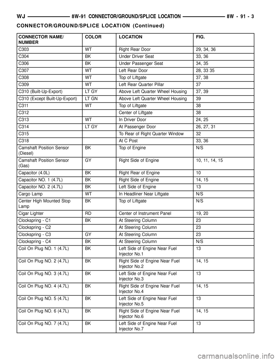
CONNECTOR NAME/
NUMBERCOLOR LOCATION FIG.
C303 WT Right Rear Door 29, 34, 36
C304 BK Under Driver Seat 33, 36
C306 BK Under Passenger Seat 34, 35
C307 WT Left Rear Door 28, 33 35
C308 WT Top of Liftgate 37, 38
C309 WT Left Rear Quarter Pillar 37
C310 (Built-Up-Export) LT GY Above Left Quarter Wheel Housing 37, 39
C310 (Except Built-Up-Export) LT GN Above Left Quarter Wheel Housing 39
C311 WT Top of Liftgate 38
C312 Center of Liftgate 38
C313 WT In Driver Door 24, 25
C314 LT GY At Passenger Door 26, 27, 31
C315 To Rear of Right Quarter Window 32
C318 At C Post 33, 36
Camshaft Position Sensor
(Diesel)BK Top of Engine N/S
Camshaft Position Sensor
(Gas)GY Right Side of Engine 10, 11, 14, 15
Capacitor (4.0L) BK Right Rear of Engine 10
Capacitor NO. 1 (4.7L) BK Right Side of Engine 14, 15
Capacitor NO. 2 (4.7L) BK Left Side of Engine 13
Cargo Lamp WT In Headliner Near Liftgate N/S
Center High Mounted Stop
LampBK Top of Liftgate N/S
Cigar Lighter RD Center of Instrument Panel 19, 20
Clockspring - C1 BK At Steering Column 23
Clockspring - C2 At Steering Column 23
Clockspring - C3 GY At Steering Column 23
Clockspring - C4 BK At Steering Column N/S
Coil On Plug NO. 1 (4.7L) BK Left Side of Engine Near Fuel
Injector No.113
Coil On Plug NO. 2 (4.7L) BK Right Side of Engine Near Fuel
Injector No.214, 15
Coil On Plug NO. 3 (4.7L) BK Left Side of Engine Near Fuel
Injector No.313
Coil On Plug NO. 4 (4.7L) BK Right Side of Engine Near Fuel
Injector No.414, 15
Coil On Plug NO. 5 (4.7L) BK Left Side of Engine Near Fuel
Injector No.513
Coil On Plug NO. 6 (4.7L) BK Right Side of Engine Near Fuel
Injector No.614, 15
Coil On Plug NO. 7 (4.7L) BK Left Side of Engine Near Fuel
Injector No.713
WJ8W-91 CONNECTOR/GROUND/SPLICE LOCATION 8W - 91 - 3
CONNECTOR/GROUND/SPLICE LOCATION (Continued)
Page 1226 of 2199

8W-97 POWER DISTRIBUTION
TABLE OF CONTENTS
page page
POWER DISTRIBUTION
DESCRIPTION..........................1
OPERATION............................1
SPECIAL TOOLS
POWER DISTRIBUTION SYSTEMS.........2
CIGAR LIGHTER OUTLET
DESCRIPTION..........................2
OPERATION............................2
DIAGNOSIS AND TESTING - CIGAR LIGHTER
OUTLET.............................2
CIGAR LIGHTER OUTLET DOOR SPRING
REMOVAL.............................3
INSTALLATION..........................3
IOD FUSE
DESCRIPTION..........................3
OPERATION............................4
REMOVAL.............................4
INSTALLATION..........................4
JUNCTION BLOCK
DESCRIPTION..........................5
OPERATION............................5
REMOVAL.............................5
INSTALLATION..........................6
POWER DISTRIBUTION CENTER
DESCRIPTION..........................7
OPERATION............................8
REMOVAL.............................8
DISASSEMBLY
POWER DISTRIBUTION CENTER
DISASSEMBLY........................9ASSEMBLY
POWER DISTRIBUTION CENTER
ASSEMBLY..........................11
INSTALLATION.........................12
POWER OUTLET
DESCRIPTION - FRONT POWER OUTLET....12
OPERATION - FRONT POWER OUTLET......12
DIAGNOSIS AND TESTING - POWER OUTLET . 12
REMOVAL.............................13
INSTALLATION.........................13
POWER OUTLET RELAY
DESCRIPTION.........................13
OPERATION...........................14
DIAGNOSIS AND TESTING - POWER OUTLET
RELAY..............................14
REMOVAL.............................15
INSTALLATION.........................15
IOD WIRE HARNESS CONNECTOR
DESCRIPTION.........................15
OPERATION...........................15
FUSE COVER
REMOVAL.............................16
INSTALLATION.........................16
REAR POWER OUTLET
DESCRIPTION - REAR POWER OUTLET.....16
OPERATION - REAR POWER OUTLET.......17
DIAGNOSIS AND TESTING - REAR POWER
OUTLET............................17
REMOVAL.............................17
INSTALLATION.........................18
POWER DISTRIBUTION
DESCRIPTION
This group covers the various standard and
optional power distribution components used on this
model. The power distribution system for this vehicle
consists of the following components:
²Power Distribution Center (PDC)
²Junction Block (JB)
²Power Outlets
The power distribution system also incorporates
various types of circuit control and protection fea-
tures, including:
²Automatic resetting circuit breakers
²Blade-type fuses
²Bus bars
²Cartridge fuses²Circuit splice blocks
²Flashers
²Fusible links
²Standard and Micro-Relays
Following are general descriptions of the major
components in the power distribution system. See the
owner's manual in the vehicle glove box for more
information on the features and use of all of the
power distribution system components. Refer to Wir-
ing Diagrams for complete circuit diagrams.
OPERATION
The power distribution system for this vehicle is
designed to provide safe, reliable, and centralized dis-
tribution points for the electrical current required to
operate all of the standard and optional factory-in-
stalled electrical and electronic powertrain, chassis,
safety, security, comfort and convenience systems. At
WJ8W-97 POWER DISTRIBUTION 8W - 97 - 1
Page 1240 of 2199
ground at all times. If not OK, repair the open
ground circuit to ground as required.
REMOVAL
(1) Disconnect and isolate the battery negative
cable.
(2) Remove the steering column opening cover
from the instrument panel. Refer toSteering Col-
umn Opening Coverin Body for the procedure.
(3) The power outlet / cigar lighter relay is located
on the left side of the combination flasher in the
junction block.
(4) Remove the power outlet / cigar lighter relay
from the junction block.
INSTALLATION
(1) Position the power outlet / cigar lighter relay in
the proper receptacle in the junction block.
(2) Align the power outlet / cigar lighter relay ter-
minals with the terminal cavities in the junction
block receptacle.
(3) Push in firmly on the power outlet / cigar
lighter relay until the terminals are fully seated in
the terminal cavities in the junction block receptacle.
(4) Install the steering column opening cover onto
the instrument panel. Refer toSteering Column
Opening Coverin Body for the procedure.
(5) Reconnect the battery negative cable.
IOD WIRE HARNESS
CONNECTOR
DESCRIPTION
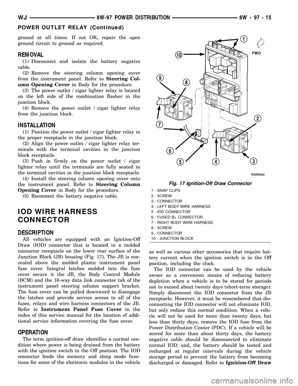
All vehicles are equipped with an Ignition-Off
Draw (IOD) connector that is located in a molded
connector receptacle on the lower rear surface of the
Junction Block (JB) housing (Fig. 17). The JB is con-
cealed above the molded plastic instrument panel
fuse cover. Integral latches molded into the fuse
cover secure it the JB, the Body Control Module
(BCM) and the 16-way data link connector tab of the
instrument panel steering column support bracket.
The fuse cover can be pulled downward to disengage
the latches and provide service access to all of the
fuses, relays and wire harness connectors of the JB.
Refer toInstrument Panel Fuse Coverin the
index of this service manual for the location of addi-
tional service information covering the fuse cover.
OPERATION
The term ignition-off draw identifies a normal con-
dition where power is being drained from the battery
with the ignition switch in the Off position. The IOD
connector feeds the memory and sleep mode func-
tions for some of the electronic modules in the vehicleas well as various other accessories that require bat-
tery current when the ignition switch is in the Off
position, including the clock.
The IOD connector can be used by the vehicle
owner as a convenient means of reducing battery
depletion when a vehicle is to be stored for periods
not to exceed about twenty days (short-term storage).
Simply disconnect the IOD connector from the JB
receptacle. However, it must be remembered that dis-
connecting the IOD connector will not eliminate IOD,
but only reduce this normal condition. When a vehi-
cle will not be used for more than twenty days, but
less than thirty days, remove the IOD fuse from the
Power Distribution Center (PDC). If a vehicle will be
stored for more than about thirty days, the battery
negative cable should be disconnected to eliminate
normal IOD; and, the battery should be tested and
recharged at regular intervals during the vehicle
storage period to prevent the battery from becoming
discharged or damaged. Refer toIgnition-Off Draw
Fig. 17 Ignition-Off Draw Connector
1 - SNAP CLIPS
2 - SCREW
3 - CONNECTOR
4 - LEFT BODY WIRE HARNESS
5 - IOD CONNECTOR
6 - FUSED B+ CONNECTOR
7 - RIGHT BODY WIRE HARNESS
8 - SCREW
9 - CONNECTOR
10 - JUNCTION BLOCK
WJ8W-97 POWER DISTRIBUTION 8W - 97 - 15
POWER OUTLET RELAY (Continued)
Page 1241 of 2199
FuseandBatteryin the index in this service man-
ual for the location of additional service information
covering the ignition-off draw fuse and the battery.
FUSE COVER
REMOVAL
(1) Disconnect and isolate the battery negative
cable.
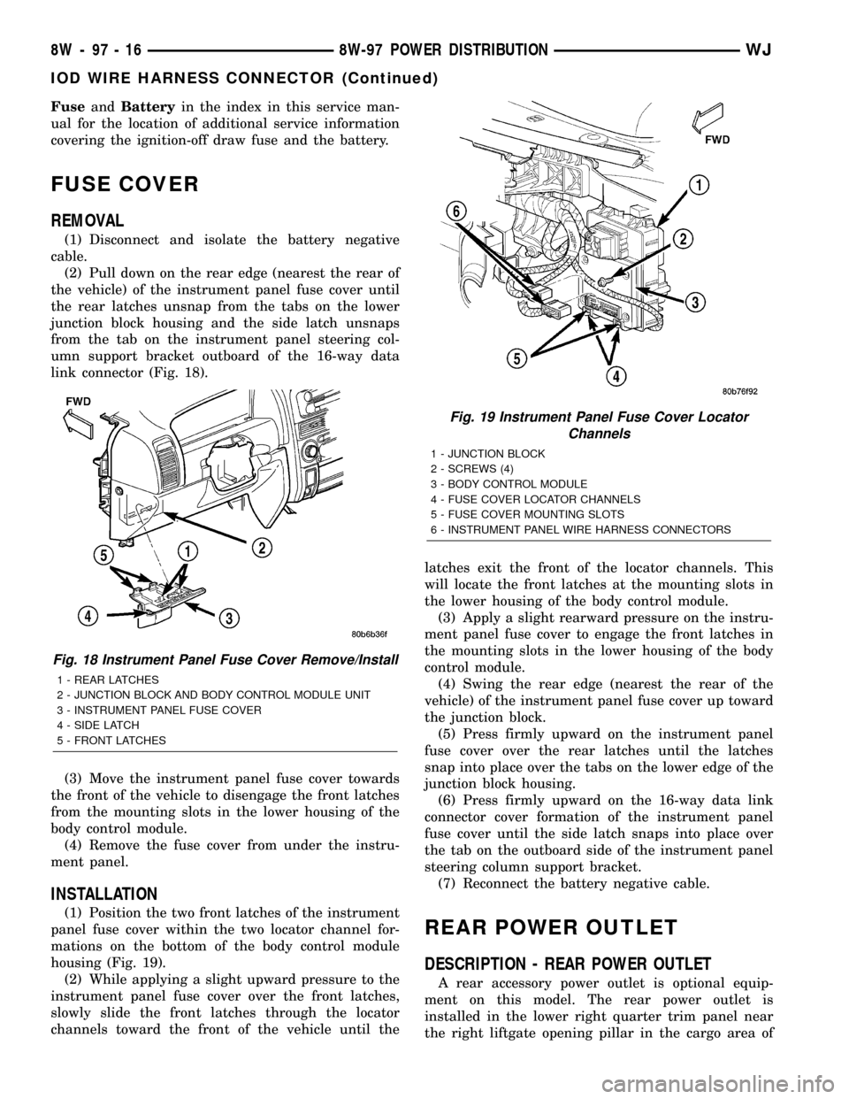
(2) Pull down on the rear edge (nearest the rear of
the vehicle) of the instrument panel fuse cover until
the rear latches unsnap from the tabs on the lower
junction block housing and the side latch unsnaps
from the tab on the instrument panel steering col-
umn support bracket outboard of the 16-way data
link connector (Fig. 18).
(3) Move the instrument panel fuse cover towards
the front of the vehicle to disengage the front latches
from the mounting slots in the lower housing of the
body control module.
(4) Remove the fuse cover from under the instru-
ment panel.
INSTALLATION
(1) Position the two front latches of the instrument
panel fuse cover within the two locator channel for-
mations on the bottom of the body control module
housing (Fig. 19).
(2) While applying a slight upward pressure to the
instrument panel fuse cover over the front latches,
slowly slide the front latches through the locator
channels toward the front of the vehicle until thelatches exit the front of the locator channels. This
will locate the front latches at the mounting slots in
the lower housing of the body control module.
(3) Apply a slight rearward pressure on the instru-
ment panel fuse cover to engage the front latches in
the mounting slots in the lower housing of the body
control module.
(4) Swing the rear edge (nearest the rear of the
vehicle) of the instrument panel fuse cover up toward
the junction block.
(5) Press firmly upward on the instrument panel
fuse cover over the rear latches until the latches
snap into place over the tabs on the lower edge of the
junction block housing.
(6) Press firmly upward on the 16-way data link
connector cover formation of the instrument panel
fuse cover until the side latch snaps into place over
the tab on the outboard side of the instrument panel
steering column support bracket.
(7) Reconnect the battery negative cable.
REAR POWER OUTLET
DESCRIPTION - REAR POWER OUTLET
A rear accessory power outlet is optional equip-
ment on this model. The rear power outlet is
installed in the lower right quarter trim panel near
the right liftgate opening pillar in the cargo area of
Fig. 18 Instrument Panel Fuse Cover Remove/Install
1 - REAR LATCHES
2 - JUNCTION BLOCK AND BODY CONTROL MODULE UNIT
3 - INSTRUMENT PANEL FUSE COVER
4 - SIDE LATCH
5 - FRONT LATCHES
Fig. 19 Instrument Panel Fuse Cover Locator
Channels
1 - JUNCTION BLOCK
2 - SCREWS (4)
3 - BODY CONTROL MODULE
4 - FUSE COVER LOCATOR CHANNELS
5 - FUSE COVER MOUNTING SLOTS
6 - INSTRUMENT PANEL WIRE HARNESS CONNECTORS
8W - 97 - 16 8W-97 POWER DISTRIBUTIONWJ
IOD WIRE HARNESS CONNECTOR (Continued)
Page 1242 of 2199
the vehicle. The power outlet base and mount are
secured by a snap fit within the quarter trim panel.
A plastic protective cap snaps into the power outlet
base when the power outlet is not being used, and
hangs from the power outlet base mount by an inte-
gral bail strap while the power outlet is in use. While
the power outlet is very similar to a cigar lighter
base unit, it does not include the two small spring-
clip retainers inside the bottom of the receptacle
shell that are used to secure the cigar lighter heating
element to the insulated contact.
The power outlet receptacle unit and the accessory
power outlet protective cap are available for service.
The power outlet receptacle cannot be repaired and,
if faulty or damaged, it must be replaced.
OPERATION - REAR POWER OUTLET
The power outlet base or receptacle shell is con-
nected to ground, and an insulated contact in the
bottom of the shell is connected to battery current.
The power outlet receives battery voltage from a fuse
in the Power Distribution Center (PDC) through a
fuse in the Junction Block (JB) at all times. Refer to
Horn/Cigar Lighter/Power Outletin Wiring Dia-
grams for the location of complete rear power outlet
circuit diagrams.
DIAGNOSIS AND TESTING - REAR POWER
OUTLET
Refer toHorn/Cigar Lighter/Power Outletin
Wiring Diagrams for the location of complete rear
power outlet circuit diagrams.
(1) Check the fused B(+) fuse in the Junction
Block (JB). If OK, go to Step 2. If not OK, repair the
shorted circuit or component as required and replace
the faulty fuse.
(2) Check for battery voltage at the fused B(+) fuse
in the JB. If OK, go to Step 3. If not OK, repair the
open fused B(+) circuit to the Power Distribution
Center (PDC) as required.
(3) Remove the plastic protective cap from the rear
power outlet receptacle. Check for continuity between
the inside circumference of the rear power outlet
receptacle and a good ground. There should be conti-
nuity. If OK, go to Step 4. If not OK, go to Step 5.
(4) Check for battery voltage at the insulated con-
tact located at the back of the rear power outlet
receptacle. If not OK, go to Step 5.(5) Disconnect and isolate the battery negative
cable. Remove the rear power outlet from the right
quarter trim panel. Check for continuity between the
ground circuit cavity of the rear power outlet wire
harness connector and a good ground. There should
be continuity. If OK, go to Step 6. If not OK, repair
the open ground circuit to ground as required.
(6) Connect the battery negative cable. Check for
battery voltage at the fused B(+) circuit cavity of the
rear power outlet wire harness connector. If OK,
replace the faulty rear power outlet receptacle base.
If not OK, repair the open fused B(+) circuit to the
JB fuse as required.
REMOVAL
(1) Disconnect and isolate the battery negative
cable.
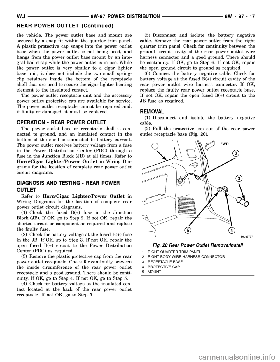
(2) Pull the protective cap out of the rear power
outlet receptacle base (Fig. 20).
Fig. 20 Rear Power Outlet Remove/Install
1 - RIGHT QUARTER TRIM PANEL
2 - RIGHT BODY WIRE HARNESS CONNECTOR
3 - RECEPTACLE BASE
4 - PROTECTIVE CAP
5 - MOUNT
WJ8W-97 POWER DISTRIBUTION 8W - 97 - 17
REAR POWER OUTLET (Continued)