2002 JEEP GRAND CHEROKEE Turn Signal on
[x] Cancel search: Turn Signal onPage 1164 of 2199
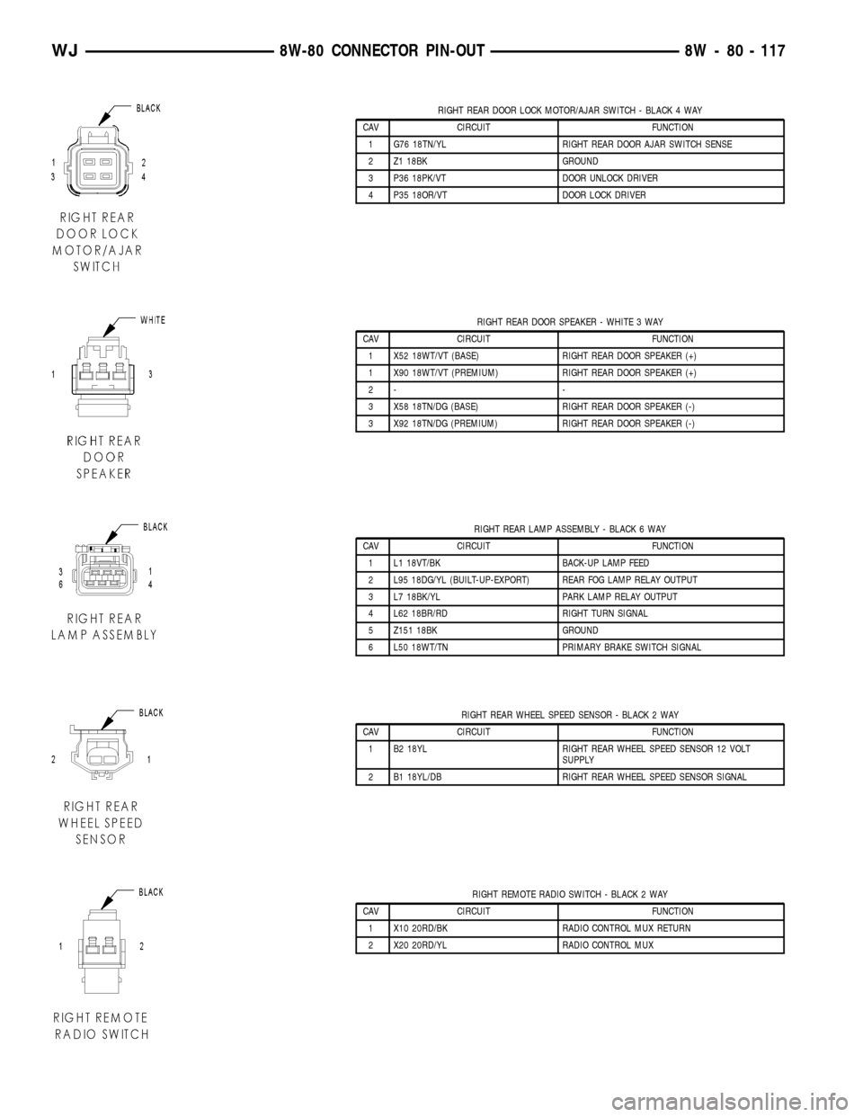
RIGHT REAR DOOR LOCK MOTOR/AJAR SWITCH - BLACK 4 WAY
CAV CIRCUIT FUNCTION
1 G76 18TN/YL RIGHT REAR DOOR AJAR SWITCH SENSE
2 Z1 18BK GROUND
3 P36 18PK/VT DOOR UNLOCK DRIVER
4 P35 18OR/VT DOOR LOCK DRIVER
RIGHT REAR DOOR SPEAKER - WHITE 3 WAY
CAV CIRCUIT FUNCTION
1 X52 18WT/VT (BASE) RIGHT REAR DOOR SPEAKER (+)
1 X90 18WT/VT (PREMIUM) RIGHT REAR DOOR SPEAKER (+)
2- -
3 X58 18TN/DG (BASE) RIGHT REAR DOOR SPEAKER (-)
3 X92 18TN/DG (PREMIUM) RIGHT REAR DOOR SPEAKER (-)
RIGHT REAR LAMP ASSEMBLY - BLACK 6 WAY
CAV CIRCUIT FUNCTION
1 L1 18VT/BK BACK-UP LAMP FEED
2 L95 18DG/YL (BUILT-UP-EXPORT) REAR FOG LAMP RELAY OUTPUT
3 L7 18BK/YL PARK LAMP RELAY OUTPUT
4 L62 18BR/RD RIGHT TURN SIGNAL
5 Z151 18BK GROUND
6 L50 18WT/TN PRIMARY BRAKE SWITCH SIGNAL
RIGHT REAR WHEEL SPEED SENSOR - BLACK 2 WAY
CAV CIRCUIT FUNCTION
1 B2 18YL RIGHT REAR WHEEL SPEED SENSOR 12 VOLT
SUPPLY
2 B1 18YL/DB RIGHT REAR WHEEL SPEED SENSOR SIGNAL
RIGHT REMOTE RADIO SWITCH - BLACK 2 WAY
CAV CIRCUIT FUNCTION
1 X10 20RD/BK RADIO CONTROL MUX RETURN
2 X20 20RD/YL RADIO CONTROL MUX
WJ8W-80 CONNECTOR PIN-OUT 8W - 80 - 117
Page 1165 of 2199
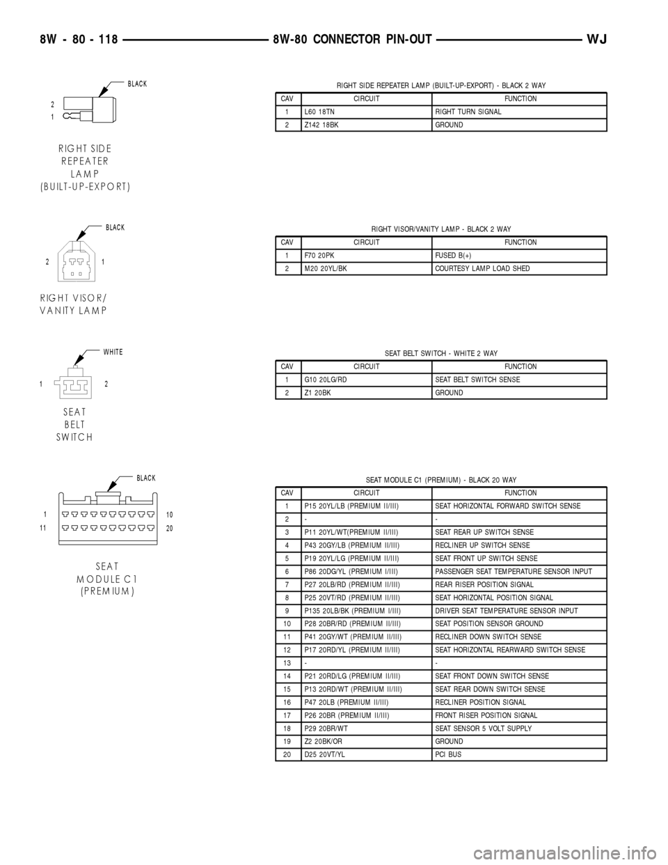
RIGHT SIDE REPEATER LAMP (BUILT-UP-EXPORT) - BLACK 2 WAY
CAV CIRCUIT FUNCTION
1 L60 18TN RIGHT TURN SIGNAL
2 Z142 18BK GROUND
RIGHT VISOR/VANITY LAMP - BLACK 2 WAY
CAV CIRCUIT FUNCTION
1 F70 20PK FUSED B(+)
2 M20 20YL/BK COURTESY LAMP LOAD SHED
SEAT BELT SWITCH - WHITE 2 WAY
CAV CIRCUIT FUNCTION
1 G10 20LG/RD SEAT BELT SWITCH SENSE
2 Z1 20BK GROUND
SEAT MODULE C1 (PREMIUM) - BLACK 20 WAY
CAV CIRCUIT FUNCTION
1 P15 20YL/LB (PREMIUM II/III) SEAT HORIZONTAL FORWARD SWITCH SENSE
2- -
3 P11 20YL/WT(PREMIUM II/III) SEAT REAR UP SWITCH SENSE
4 P43 20GY/LB (PREMIUM II/III) RECLINER UP SWITCH SENSE
5 P19 20YL/LG (PREMIUM II/III) SEAT FRONT UP SWITCH SENSE
6 P86 20DG/YL (PREMIUM I/III) PASSENGER SEAT TEMPERATURE SENSOR INPUT
7 P27 20LB/RD (PREMIUM II/III) REAR RISER POSITION SIGNAL
8 P25 20VT/RD (PREMIUM II/III) SEAT HORIZONTAL POSITION SIGNAL
9 P135 20LB/BK (PREMIUM I/III) DRIVER SEAT TEMPERATURE SENSOR INPUT
10 P28 20BR/RD (PREMIUM II/III) SEAT POSITION SENSOR GROUND
11 P41 20GY/WT (PREMIUM II/III) RECLINER DOWN SWITCH SENSE
12 P17 20RD/YL (PREMIUM II/III) SEAT HORIZONTAL REARWARD SWITCH SENSE
13 - -
14 P21 20RD/LG (PREMIUM II/III) SEAT FRONT DOWN SWITCH SENSE
15 P13 20RD/WT (PREMIUM II/III) SEAT REAR DOWN SWITCH SENSE
16 P47 20LB (PREMIUM II/III) RECLINER POSITION SIGNAL
17 P26 20BR (PREMIUM II/III) FRONT RISER POSITION SIGNAL
18 P29 20BR/WT SEAT SENSOR 5 VOLT SUPPLY
19 Z2 20BK/OR GROUND
20 D25 20VT/YL PCI BUS
8W - 80 - 118 8W-80 CONNECTOR PIN-OUTWJ
Page 1170 of 2199
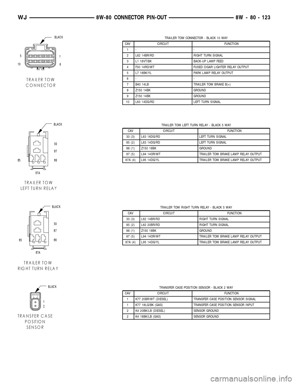
TRAILER TOW CONNECTOR - BLACK 10 WAY
CAV CIRCUIT FUNCTION
1- -
2 L62 14BR/RD RIGHT TURN SIGNAL
3 L1 18VT/BK BACK-UP LAMP FEED
4 F30 14RD/WT FUSED CIGAR LIGHTER RELAY OUTPUT
5 L7 18BK/YL PARK LAMP RELAY OUTPUT
6- -
7 B40 14LB TRAILER TOW BRAKE B(+)
8 Z150 14BK GROUND
9 Z150 14BK GROUND
10 L63 14DG/RD LEFT TURN SIGNAL
TRAILER TOW LEFT TURN RELAY - BLACK 5 WAY
CAV CIRCUIT FUNCTION
30 (3) L63 16DG/RD LEFT TURN SIGNAL
85 (2) L63 14DG/RD LEFT TURN SIGNAL
86 (1) Z150 18BK GROUND
87 (5) L94 14OR/WT TRAILER TOW BRAKE LAMP RELAY OUTPUT
87A (4) L95 14DG/YL TRAILER TOW BRAKE LAMP RELAY OUTPUT
TRAILER TOW RIGHT TURN RELAY - BLACK 5 WAY
CAV CIRCUIT FUNCTION
30 (3) L62 14BR/RD RIGHT TURN SIGNAL
85 (2) L62 20BR/RD RIGHT TURN SIGNAL
86 (1) Z150 18BK GROUND
87 (5) L94 14OR/WT TRAILER TOW BRAKE LAMP RELAY OUTPUT
87A (4) L95 14DG/YL TRAILER TOW BRAKE LAMP RELAY OUTPUT
TRANSFER CASE POSITION SENSOR - BLACK 2 WAY
CAV CIRCUIT FUNCTION
1 K77 20BR/WT (DIESEL) TRANSFER CASE POSITION SENSOR SIGNAL
1 K77 18LG/BK (GAS) TRANSFER CASE POSITION SENSOR INPUT
2 K4 20BK/LB (DIESEL) SENSOR GROUND
2 K4 18BK/LB (GAS) SENSOR GROUND
WJ8W-80 CONNECTOR PIN-OUT 8W - 80 - 123
Page 1182 of 2199
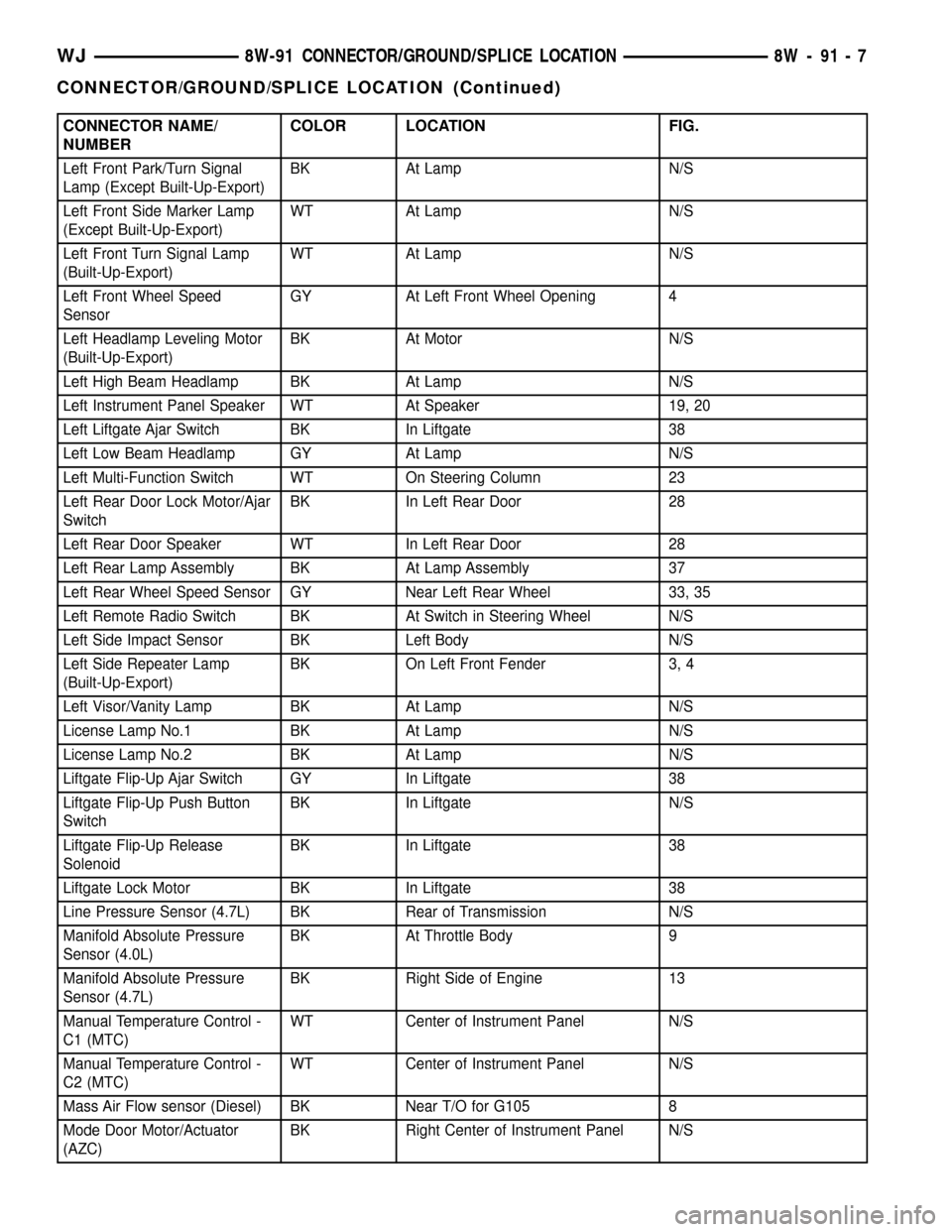
CONNECTOR NAME/
NUMBERCOLOR LOCATION FIG.
Left Front Park/Turn Signal
Lamp (Except Built-Up-Export)BK At Lamp N/S
Left Front Side Marker Lamp
(Except Built-Up-Export)WT At Lamp N/S
Left Front Turn Signal Lamp
(Built-Up-Export)WT At Lamp N/S
Left Front Wheel Speed
SensorGY At Left Front Wheel Opening 4
Left Headlamp Leveling Motor
(Built-Up-Export)BK At Motor N/S
Left High Beam Headlamp BK At Lamp N/S
Left Instrument Panel Speaker WT At Speaker 19, 20
Left Liftgate Ajar Switch BK In Liftgate 38
Left Low Beam Headlamp GY At Lamp N/S
Left Multi-Function Switch WT On Steering Column 23
Left Rear Door Lock Motor/Ajar
SwitchBK In Left Rear Door 28
Left Rear Door Speaker WT In Left Rear Door 28
Left Rear Lamp Assembly BK At Lamp Assembly 37
Left Rear Wheel Speed Sensor GY Near Left Rear Wheel 33, 35
Left Remote Radio Switch BK At Switch in Steering Wheel N/S
Left Side Impact Sensor BK Left Body N/S
Left Side Repeater Lamp
(Built-Up-Export)BK On Left Front Fender 3, 4
Left Visor/Vanity Lamp BK At Lamp N/S
License Lamp No.1 BK At Lamp N/S
License Lamp No.2 BK At Lamp N/S
Liftgate Flip-Up Ajar Switch GY In Liftgate 38
Liftgate Flip-Up Push Button
SwitchBK In Liftgate N/S
Liftgate Flip-Up Release
SolenoidBK In Liftgate 38
Liftgate Lock Motor BK In Liftgate 38
Line Pressure Sensor (4.7L) BK Rear of Transmission N/S
Manifold Absolute Pressure
Sensor (4.0L)BK At Throttle Body 9
Manifold Absolute Pressure
Sensor (4.7L)BK Right Side of Engine 13
Manual Temperature Control -
C1 (MTC)WT Center of Instrument Panel N/S
Manual Temperature Control -
C2 (MTC)WT Center of Instrument Panel N/S
Mass Air Flow sensor (Diesel) BK Near T/O for G105 8
Mode Door Motor/Actuator
(AZC)BK Right Center of Instrument Panel N/S
WJ8W-91 CONNECTOR/GROUND/SPLICE LOCATION 8W - 91 - 7
CONNECTOR/GROUND/SPLICE LOCATION (Continued)
Page 1185 of 2199
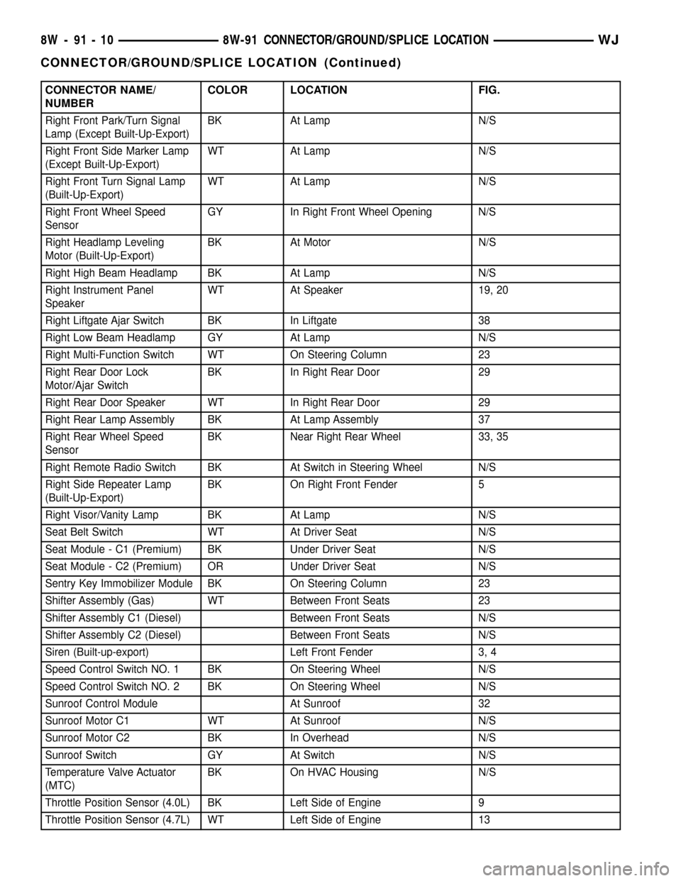
CONNECTOR NAME/
NUMBERCOLOR LOCATION FIG.
Right Front Park/Turn Signal
Lamp (Except Built-Up-Export)BK At Lamp N/S
Right Front Side Marker Lamp
(Except Built-Up-Export)WT At Lamp N/S
Right Front Turn Signal Lamp
(Built-Up-Export)WT At Lamp N/S
Right Front Wheel Speed
SensorGY In Right Front Wheel Opening N/S
Right Headlamp Leveling
Motor (Built-Up-Export)BK At Motor N/S
Right High Beam Headlamp BK At Lamp N/S
Right Instrument Panel
SpeakerWT At Speaker 19, 20
Right Liftgate Ajar Switch BK In Liftgate 38
Right Low Beam Headlamp GY At Lamp N/S
Right Multi-Function Switch WT On Steering Column 23
Right Rear Door Lock
Motor/Ajar SwitchBK In Right Rear Door 29
Right Rear Door Speaker WT In Right Rear Door 29
Right Rear Lamp Assembly BK At Lamp Assembly 37
Right Rear Wheel Speed
SensorBK Near Right Rear Wheel 33, 35
Right Remote Radio Switch BK At Switch in Steering Wheel N/S
Right Side Repeater Lamp
(Built-Up-Export)BK On Right Front Fender 5
Right Visor/Vanity Lamp BK At Lamp N/S
Seat Belt Switch WT At Driver Seat N/S
Seat Module - C1 (Premium) BK Under Driver Seat N/S
Seat Module - C2 (Premium) OR Under Driver Seat N/S
Sentry Key Immobilizer Module BK On Steering Column 23
Shifter Assembly (Gas) WT Between Front Seats 23
Shifter Assembly C1 (Diesel) Between Front Seats N/S
Shifter Assembly C2 (Diesel) Between Front Seats N/S
Siren (Built-up-export) Left Front Fender 3, 4
Speed Control Switch NO. 1 BK On Steering Wheel N/S
Speed Control Switch NO. 2 BK On Steering Wheel N/S
Sunroof Control Module At Sunroof 32
Sunroof Motor C1 WT At Sunroof N/S
Sunroof Motor C2 BK In Overhead N/S
Sunroof Switch GY At Switch N/S
Temperature Valve Actuator
(MTC)BK On HVAC Housing N/S
Throttle Position Sensor (4.0L) BK Left Side of Engine 9
Throttle Position Sensor (4.7L) WT Left Side of Engine 13
8W - 91 - 10 8W-91 CONNECTOR/GROUND/SPLICE LOCATIONWJ
CONNECTOR/GROUND/SPLICE LOCATION (Continued)
Page 1299 of 2199
(9) Lower the engine until it is properly located on
the engine mounts.
(10) Install the through bolts and tighten the nuts.
(11) Lower the jack stand and remove the piece of
wood.
(12) Install the engine flywheel and transmission
torque converter housing access cover.
(13) Install the engine starter motor. (Refer to 8 -
ELECTRICAL/STARTING/STARTER MOTOR -
INSTALLATION).
(14) Connect the exhaust pipe to the hanger and to
the engine exhaust manifold.
(15) Install transmission oil cooling lines (if
equipped) and oxygen sensor wiring supports that
attach to the oil pan studs.
(16) Install the oil pan drain plug (Fig. 81).
Tighten the plug to 34 N´m (25 ft. lbs.) torque.
(17) Lower the vehicle.
(18) Connect negative cable to battery.
(19) Fill the oil pan with engine oil to the specified
level.
WARNING: USE EXTREME CAUTION WHEN THE
ENGINE IS OPERATING. DO NOT STAND IN A
DIRECT LINE WITH THE FAN. DO NOT PUT YOUR
HANDS NEAR THE PULLEYS, BELTS OR FAN. DO
NOT WEAR LOOSE CLOTHING.
(20) Start the engine and inspect for leaks.
ENGINE OIL PRESSURE
SENSOR
DESCRIPTION
The 3±wire, solid-state engine oil pressure sensor
(sending unit) is located in an engine oil pressure
gallery.
OPERATION
The oil pressure sensor uses three circuits. They
are:
²A 5±volt power supply from the Powertrain Con-
trol Module (PCM)
²A sensor ground through the PCM's sensor
return
²A signal to the PCM relating to engine oil pres-
sure
The oil pressure sensor has a 3±wire electrical
function very much like the Manifold Absolute Pres-
sure (MAP) sensor. Meaning different pressures
relate to different output voltages.
A 5±volt supply is sent to the sensor from the PCM
to power up the sensor. The sensor returns a voltage
signal back to the PCM relating to engine oil pres-
sure. This signal is then transferred (bussed) to theinstrument panel on either a CCD or PCI bus circuit
(depending on vehicle line) to operate the oil pressure
gauge and the check gauges lamp. Ground for the
sensor is provided by the PCM through a low-noise
sensor return.
OIL PUMP
REMOVAL
A gear-type oil pump is mounted at the underside
of the cylinder block opposite the No.4 main bearing.
(1) Drain the engine oil.
(2) Remove the oil pan (Refer to 9 - ENGINE/LU-
BRICATION/OIL PAN - REMOVAL).
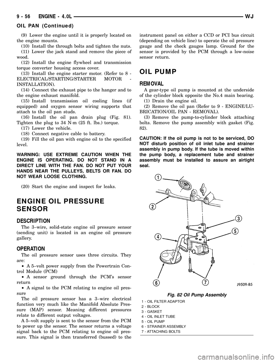
(3) Remove the pump-to-cylinder block attaching
bolts. Remove the pump assembly with gasket (Fig.
82).
CAUTION: If the oil pump is not to be serviced, DO
NOT disturb position of oil inlet tube and strainer
assembly in pump body. If the tube is moved within
the pump body, a replacement tube and strainer
assembly must be installed to assure an airtight
seal.
Fig. 82 Oil Pump Assembly
1 - OIL FILTER ADAPTOR
2 - BLOCK
3 - GASKET
4 - OIL INLET TUBE
5 - OIL PUMP
6 - STRAINER ASSEMBLY
7 - ATTACHING BOLTS
9 - 56 ENGINE - 4.0LWJ
OIL PAN (Continued)
Page 1376 of 2199

NOTE: When installing oil pan gasket/windage tray,
start four pan bolts at each corner before tightening
oil pickup tube. This will keep pan gasket in align-
ment.
(3) Install oil pump pick-up tube using a new
O-ring. First tighten bolt at O-ring end of tube to 28
N´m (20 ft. lbs.). Tighten remain tube support fasten-
ers to 28 N´m (20 ft. lbs.).
(4) Install oil pan and tighten fasteners to 15 N´m
(11 ft. lbs.) (Fig. 95).
(5) Reconnect transmission oil cooler lines to oil
pan stud bolt.
(6) Install starter (Refer to 8 - ELECTRICAL/
STARTING/STARTER MOTOR - INSTALLATION).
(7) Install exhaust system Y-pipe.
(8) Install structural cover (Refer to 9 - ENGINE/
ENGINE BLOCK/STRUCTURAL COVER - INSTAL-
LATION).
(9) Lower vehicle.
(10) Fill engine with proper amount of oil (Refer to
LUBRICATION & MAINTENANCE/FLUID TYPES -
SPECIFICATIONS).
(11) Connect negative cable to battery.
OIL PRESSURE SENSOR/
SWITCH
DESCRIPTION
The 3±wire, solid-state engine oil pressure sensor
(sending unit) is located in an engine oil pressure
gallery.
OPERATION
The oil pressure sensor uses three circuits. They are:
²A 5±volt power supply from the Powertrain Con-
trol Module (PCM)
²A sensor ground through the PCM's sensor
return
²
A signal to the PCM relating to engine oil pressure
The oil pressure sensor has a 3±wire electrical
function very much like the Manifold Absolute Pres-
sure (MAP) sensor. Meaning different pressures
relate to different output voltages.
A 5±volt supply is sent to the sensor from the PCM
to power up the sensor. The sensor returns a voltage
signal back to the PCM relating to engine oil pres-
sure. This signal is then transferred (bussed) to the
instrument panel on either a CCD or PCI bus circuit
(depending on vehicle line) to operate the oil pressure
gauge and the check gauges lamp. Ground for the
sensor is provided by the PCM through a low-noise
sensor return.
REMOVAL
(1) Disconnect the negative cable from the battery.
(2) Raise vehicle on hoist.
(3) Remove front splash shield.
(4) Disconnect oil pressure sender wire (Fig. 96).
(5) Remove the pressure sender (Fig. 96).
INSTALLATION
(1) Install oil pressure sender.
(2) Connect oil pressure sender wire.
(3) Install front splash shield.
(4) Lower vehicle.
(5) Connect the negative battery cable.
Fig. 95 Oil Pan Tightening Sequence
Fig. 96 Oil Pressure Sending Unit
1 - BELT
2 - OIL PRESSURE SENSOR
3 - OIL FILTER
4 - ELEC. CONNECTOR
WJENGINE - 4.7L 9 - 133
OIL PAN (Continued)
Page 1426 of 2199
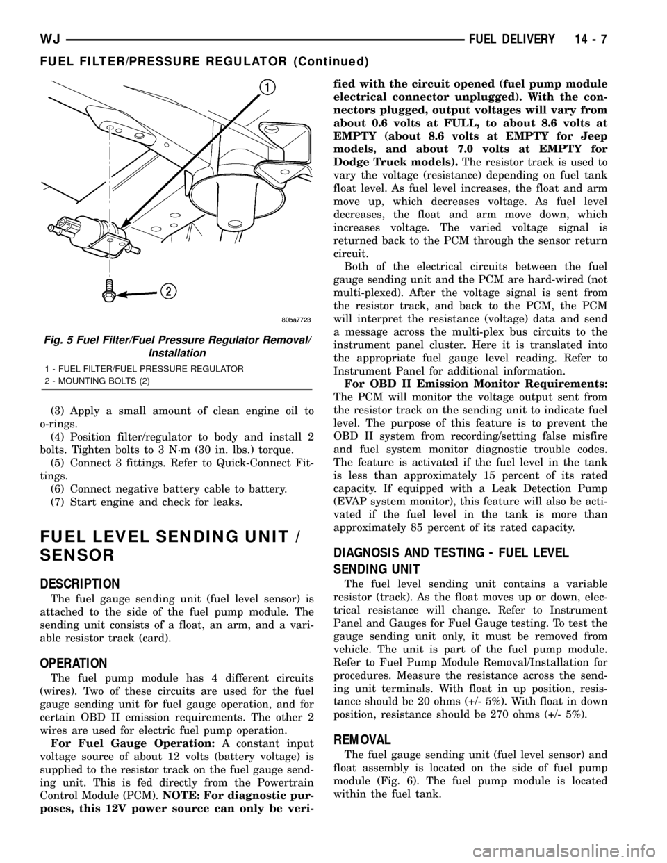
(3) Apply a small amount of clean engine oil to
o-rings.
(4) Position filter/regulator to body and install 2
bolts. Tighten bolts to 3 N´m (30 in. lbs.) torque.
(5) Connect 3 fittings. Refer to Quick-Connect Fit-
tings.
(6) Connect negative battery cable to battery.
(7) Start engine and check for leaks.
FUEL LEVEL SENDING UNIT /
SENSOR
DESCRIPTION
The fuel gauge sending unit (fuel level sensor) is
attached to the side of the fuel pump module. The
sending unit consists of a float, an arm, and a vari-
able resistor track (card).
OPERATION
The fuel pump module has 4 different circuits
(wires). Two of these circuits are used for the fuel
gauge sending unit for fuel gauge operation, and for
certain OBD II emission requirements. The other 2
wires are used for electric fuel pump operation.
For Fuel Gauge Operation:A constant input
voltage source of about 12 volts (battery voltage) is
supplied to the resistor track on the fuel gauge send-
ing unit. This is fed directly from the Powertrain
Control Module (PCM).NOTE: For diagnostic pur-
poses, this 12V power source can only be veri-fied with the circuit opened (fuel pump module
electrical connector unplugged). With the con-
nectors plugged, output voltages will vary from
about 0.6 volts at FULL, to about 8.6 volts at
EMPTY (about 8.6 volts at EMPTY for Jeep
models, and about 7.0 volts at EMPTY for
Dodge Truck models).The resistor track is used to
vary the voltage (resistance) depending on fuel tank
float level. As fuel level increases, the float and arm
move up, which decreases voltage. As fuel level
decreases, the float and arm move down, which
increases voltage. The varied voltage signal is
returned back to the PCM through the sensor return
circuit.
Both of the electrical circuits between the fuel
gauge sending unit and the PCM are hard-wired (not
multi-plexed). After the voltage signal is sent from
the resistor track, and back to the PCM, the PCM
will interpret the resistance (voltage) data and send
a message across the multi-plex bus circuits to the
instrument panel cluster. Here it is translated into
the appropriate fuel gauge level reading. Refer to
Instrument Panel for additional information.
For OBD II Emission Monitor Requirements:
The PCM will monitor the voltage output sent from
the resistor track on the sending unit to indicate fuel
level. The purpose of this feature is to prevent the
OBD II system from recording/setting false misfire
and fuel system monitor diagnostic trouble codes.
The feature is activated if the fuel level in the tank
is less than approximately 15 percent of its rated
capacity. If equipped with a Leak Detection Pump
(EVAP system monitor), this feature will also be acti-
vated if the fuel level in the tank is more than
approximately 85 percent of its rated capacity.
DIAGNOSIS AND TESTING - FUEL LEVEL
SENDING UNIT
The fuel level sending unit contains a variable
resistor (track). As the float moves up or down, elec-
trical resistance will change. Refer to Instrument
Panel and Gauges for Fuel Gauge testing. To test the
gauge sending unit only, it must be removed from
vehicle. The unit is part of the fuel pump module.
Refer to Fuel Pump Module Removal/Installation for
procedures. Measure the resistance across the send-
ing unit terminals. With float in up position, resis-
tance should be 20 ohms (+/- 5%). With float in down
position, resistance should be 270 ohms (+/- 5%).
REMOVAL
The fuel gauge sending unit (fuel level sensor) and
float assembly is located on the side of fuel pump
module (Fig. 6). The fuel pump module is located
within the fuel tank.
Fig. 5 Fuel Filter/Fuel Pressure Regulator Removal/
Installation
1 - FUEL FILTER/FUEL PRESSURE REGULATOR
2 - MOUNTING BOLTS (2)
WJFUEL DELIVERY 14 - 7
FUEL FILTER/PRESSURE REGULATOR (Continued)