2002 Hyundai Grandeur maintenance
[x] Cancel search: maintenancePage 208 of 230

DO-IT-YOURSELF MAINTENANCE 6- 31
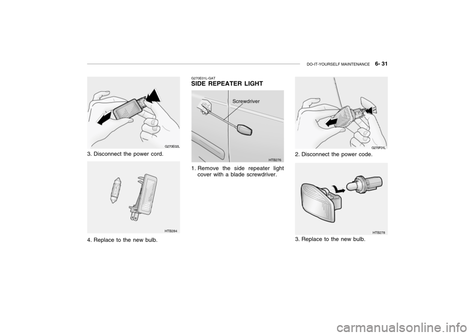
2. Disconnect the power code. G270F01L
3. Replace to the new bulb.
HTB278
G270E02L
3. Disconnect the power cord.
4. Replace to the new bulb.
HTB284 G270E01L-GAT SIDE REPEATER LIGHT
1. Remove the side repeater light
cover with a blade screwdriver.
HTB276
Screwdriver
Page 209 of 230

6- 32 DO-IT-YOURSELF MAINTENANCE
G270E02L
HTB284
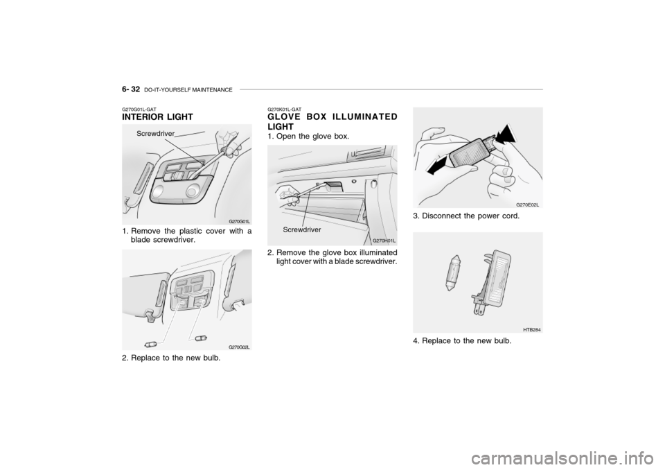
3. Disconnect the power cord.
4. Replace to the new bulb.
G270K01L-GAT
GLOVE BOX ILLUMINATED LIGHT
1. Open the glove box.
2. Remove the glove box illuminated
light cover with a blade screwdriver. G270H01L
Screwdriver
G270G01L-GAT INTERIOR LIGHT
G270G01L
1. Remove the plastic cover with a blade screwdriver.
2. Replace to the new bulb. G270G02L
Screwdriver
Page 210 of 230

DO-IT-YOURSELF MAINTENANCE 6- 33
1456
4
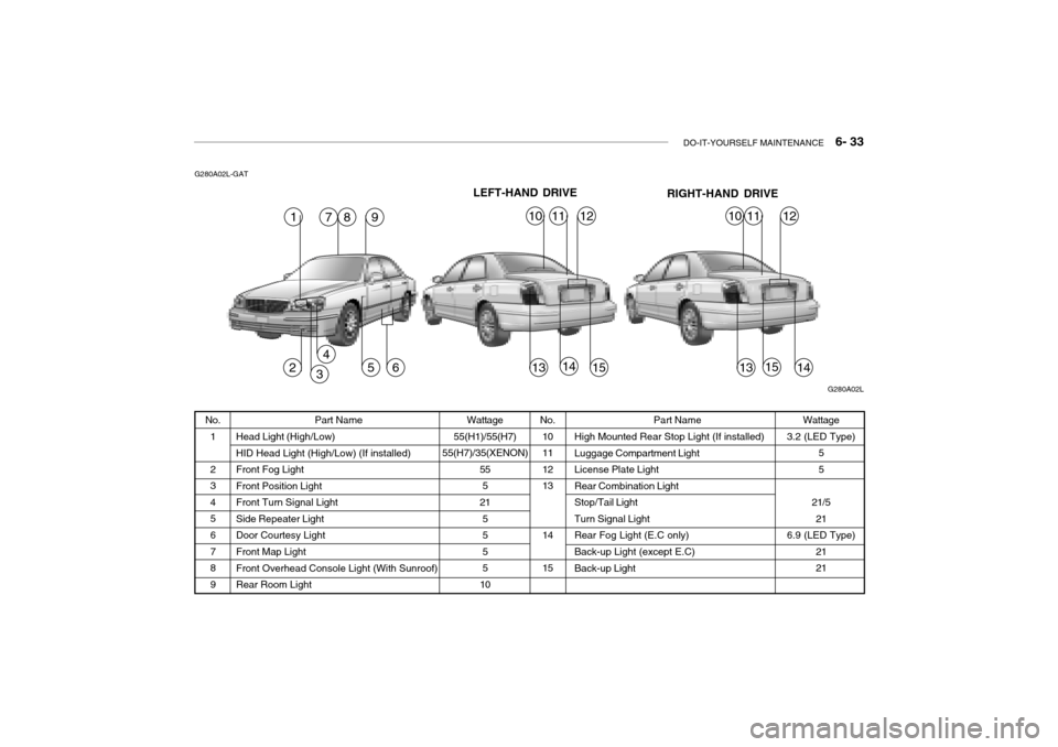
Part Name
Head Light (High/Low) HID Head Light (High/Low) (If installed) Front Fog LightFront Position LightFront Turn Signal LightSide Repeater LightDoor Courtesy Light Front Map Light Front Overhead Console Light (With Sunroof)Rear Room Light Wattage
55(H1)/55(H7)
55(H7)/35(XENON) 555
21 5555
10
G280A02L-GAT
Wattage
3.2 (LED Type) 5 5
21/5 21
6.9 (LED Type) 2121
No.
1 2 345 6 789 No.
10111213 14 15 Part Name
High Mounted Rear Stop Light (If installed) Luggage Compartment Light License Plate LightRear Combination LightStop/Tail LightTurn Signal LightRear Fog Light (E.C only) Back-up Light (except E.C) Back-up Light
G280A02L
1978
231315
101112
LEFT-HAND DRIVE RIGHT-HAND DRIVE
151413
101112
Page 211 of 230

6- 34 DO-IT-YOURSELF MAINTENANCE
G200C01L-GAT JUNCTION BOX DESCRIPTION Under Hood Junction Box
G200C01L
NOTE: Not all junction box description in this manual
may be applicable to your vehicle. It is accurate at the time of printing. When you inspect the junction box on your vehicle, refer to the junction box label. DESCRIPTION
FUEL PUMP
HEAD LIGHT(Lo-LH) ABS
INJECTOR
A/C COMPRESSOR A/T
MAIN
IGNITION COIL
OXYGEN SENSOR EGR
HORN
HEAD LIGHT(HI)
HEAD LIGHT(Lo-RH) DRL
FOG LIGHT DIODE 1
SPARE
SPARE
SPARE
SPARE
DIODE 2
BLOWER
POWER FUSE 2 POWER AMPSUNROOF
TAIL LIGHT
POWER FUSE 1 ECU
REAR DEFOGGER CONDENSER
POWER WINDOW IGNITION1/2ABS 1/2
RADIATOR FUSE
RATING
20A15A10A10A10A20A30A 20A 15A 15A10A15A20A15A15A 30A 20A15A10A 30A 30A20A15A20A30A10A30A20A40A
30A/30A30A/30A 30A PROTECTED COMPONENTS
Fuel pump relay
Head light relay (Low-LH)
ABS controls, Cruise control module, ETS control module
Limp home valve, ETS controls, Injector
A/C relay
A/T control relay, TCM, Engine control relayMFI controls
Ignition coil, A/T pulse generator, ECM, Ignition failure
sensor, E/TCM
ETS relay, MFI controls
A/C relay, MFI controls, EGR solenoid
Horn relay
Head light relay (High)
HID head light relay
DRL control module, Siren
Fog light relay - -----
Blower relayFuse 4, 20, 24, 25
Audio amp module
Data link connector, Sunroof relay, Home link connector
Tail light relayFuse 1, 7, 17, 18, 19
ETS control module, ECM, E/TCM, Generator
Rear window defogger relay
A/C fan relay #1
Power window relay, IMS controls
Ignition switchABS controlsRadiator fan relay
Page 212 of 230

DO-IT-YOURSELF MAINTENANCE 6- 35
FUSE RATING
25A 20A10A15A10A10A10A15A10A10A15A 10A 10A 10A20A10A 15A 10A15A10A10A15A10A20A 10A 10A 10A 10A10A10A 10A 10A PROTECTED COMPONENTS
Power seat
Seat warmerEPS controls
ETS relay
(HID) Head lights, DRL controls, AQS sensor
Blower & A/C controls
Turn & Hazard controlsNot used
Cruise switch, Instrument cluster
Head light leveling switch, Rain sensor, IMS controls
Rain sensor relay, Wiper & Washer controls
Home link connector, Left (Right) vanity lights, Sunroof, Blower & A/C controls,Electronic chrome mirrorNot used
Audio
Front (Rear) cigarette lighter, Accessory socket
IMS controls, Driver door module, RheostatNot used
Rear for light relay
Stop lights, Left (Right) personal lights, Left (Right) rear door lights
Door warning & Ignition key illumination, Courtesy lightsInstrument clusterSRS controls
Automatic transaxle controls, Back-up light switch, Vehicle speed sensor
Fuel filler door & Trunk lid opener, Driver (Assister) door module
Multipurpose check connector, Audio, lmmobiilizer controls, Trip computers, Digital
clock, Blower & A/C controls, Instrument cluster
Left (Right) inside lights, (HID) Head lights, Fog light relay, Right HID turn signal light,Right rear combination light
Stop light failure relay
Immobilizer controls, TCS switch, Trip computers, Instrument cluster
ETACM, Hazard switch, Auto light sensor
Antenna, Blower & A/C controls, Left (Right) outside mirror motor & Folding motor
(HID) Head lights, Front (Rear) cigarette lighters, Left (Right) license lights, Left HID
Turn signal light, Left rear combination lightBurglar alarm relay, Transaxle range switch, Start relay, ETS controlsDESCRIPTION P/SEAT
S/HTR EPSETS
H/LP
A/CON SW HAZARDSPARE
CRUISE IMS
WIPER
ETACS
SPARE AUDIO
C/LIGHTER MIRRORSPARE
RR FOG
STOP LP
ROOM LP
A/BAG IND A/BAGB/UP
T/LID
D/CLOCK
RH TAILSPARE
CLUSTER T/SIG
RR HTD IND
LH TAIL
START
G200D01L-GAT
Instrument Panel Junction Box
G200D01L
Page 214 of 230

7- 2 EMISSION CONTROL SYSTEMS
H010A01A-GAT
EMISSION CONTROL SYSTEM (If Installed)
Your Hyundai is equipped with an
emission control system to meet all requirements of the Emission prohibi-tion rules of your province.
There are three emission control sys-
tems which are as follows.
1) Crankcase emission control sys-
tem
2) Evaporative emission control sys-
tem
3) Exhaust emission control system
In order to assure the proper function
of the emission control systems, it is recommended that you have your car inspected and maintained by an au-thorized Hyundai dealer in accordance with the maintenance schedule in this manual. H010B01A-AAT
1. Crankcase Emission Control
System
The positive crankcase ventilation
system is employed to prevent airpollution caused by blow-by gasesbeing emitted from the crankcase. This system supplies fresh air to the crankcase through the air intake hose.Inside the crankcase, the fresh air mixes with blow-by gases, which then pass through the PCV valve and intothe induction system.
H010C02Y-GAT
2. Evaporative Emission
Control System
The Evaporative Emission Control
System is designed to prevent fuel vapors from escaping into the atmo- sphere. Canister
While the engine is inoperative, fuel
vapors generated inside the fuel tank are absorbed and stored in the canis- ter. When the engine is running, the fuel vapors absorbed in the canisterare drawn into the induction system through the purge control solenoidvalve. Purge Control Solenoid Valve
The purge control solenoid valve is
controlled by the ECM; when the en- gine coolant temperature is low, and during idling, it closes, so that evapo- rated fuel is not taken into the surgetank. After engine warm-up, during ordinary driving, it opens so as to introduce evaporated fuel to the surgetank.
H010D01A-AAT
3. Exhaust Emission Control
System
The exhaust emission control system
is a highly effective system whichcontrols exhaust emission while main- taining good vehicle performance.
H010E01Y-GAT
EGR System
This system helps control nitrogen
oxides by recirculating a part of the exhaust gas into the engine, therebyreducing cylinder combustion tem- perature.
Page 228 of 230

10- 4 INDEX
H Hazard Warning System........................................... 1-52
Headlight Aiming Adjustment .................................... 6-25
Headlight Leveling Device Syst em ...........................1-72
Heating and Ventilation ................................. 1-76 ~ 1-89
Air flow control ..................... 1-78 ~ 1-79, 1-87 ~ 1-89
Air intake control .................. 1-77 ~ 1-78, 1-86 ~ 1-87
Bi-level heating ....................................................... 1-80
Fan speed control .................................................. 1-77
Temperature control ............................................... 1-80
High-Mounted Rear Stop L ight .................................1-66
Hood Release ........................................................... 1-68
Horn .......................................................................... 1-70
I Ignition Switch ............................................................. 2-3
Illuminated Ignition Switch .......................................... 1-5 Immobilizer Sy stem ........................................... 1-4 ~ 1-5
Instrument Cluster and Indicator Lights ....... 1-39 ~ 1-44
Instrument Panel Light Control (Rheost at) ............... 1-55
Intergrated Memory System (I. M. S) .......... 1-15 ~ 1-16 Interior Light Interior light ................................................ 1-60 ~ 1-61
Map light ................................................................ 1-60
Personal light ......................................................... 1-61
Intermittent Wiper ..................................................... 1-51
J Jump Starting .................................................... 3-2 ~ 3-3 K
Key .................................................................... 1-3 ~ 1-4
If you lose your keys ............................................. 3-12
Positions ......................................................... 2-3 ~ 2-4
L Lubrication Chart ......................................................... 9-4
Luggage Net ............................................................. 1-69
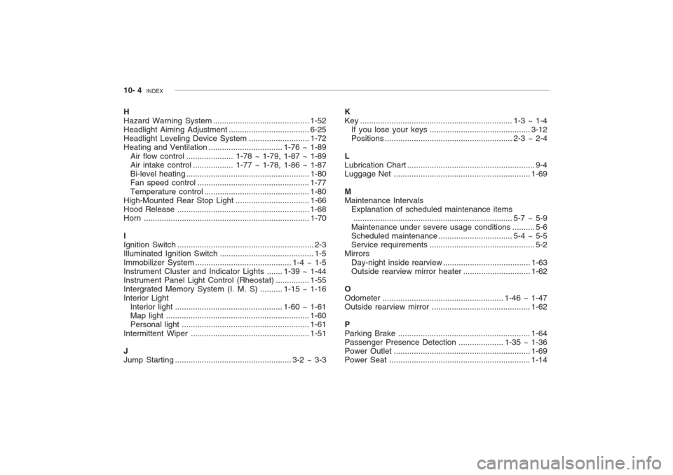
MMaintenance Intervals Explanation of scheduled maintenance items....................................................................... 5-7 ~ 5-9
Maintenance under severe usage cond itions .......... 5-6
Scheduled maintenance ................................. 5-4 ~ 5-5
Service requ irements............................................... 5-2
Mirrors
Day-night inside rearview ....................................... 1-63
Outside rearview mirror heat er ..............................1-62
O
Odometer ...................................................... 1-46 ~ 1-47 Outside rearview mirror ............................................ 1-62
P Parking Brake ........................................................... 1-64
Passenger Presence Detec tion .................... 1-35 ~ 1-36
Power Outle t ............................................................. 1-69
Power Seat ............................................................... 1-14