Page 354 of 428
3- 8 WHAT TO DO IN AN EMERGENCY
HTB149
SD070E1-E 3. Loosen Wheel Nuts The wheel nuts should be loosened slightly before raising the car. To loosen the nuts, turn the wheel brace counter- clockwise. Ensure that the wheel bracesocket is seated properly on the nut and that it cannot slip. Do not remove the nuts at this stage.Flat tyre
HTB156
SD070D1-E 2. Block the Wheel Block the wheel that is diagonally op- posite from the flat tyre to prevent the vehicle from rolling when the car israised on the jack.
Take out the jack case and tool bag, then remove the spare tyre from the luggage room. NOTE: The jack case is located on the spare tyre in the vehicle.
Hang the luggage room mat to the mat hanger and remove the luggage under tray (If installed)
D060B01TB-EAT 1. Obtain Spare Tyre and Tool
HTB224
HTB296
Mat hanger
Page 355 of 428

WHAT TO DO IN AN EMERGENCY 3- 9
SD070H1-E 6. Changing Wheels
HTB157
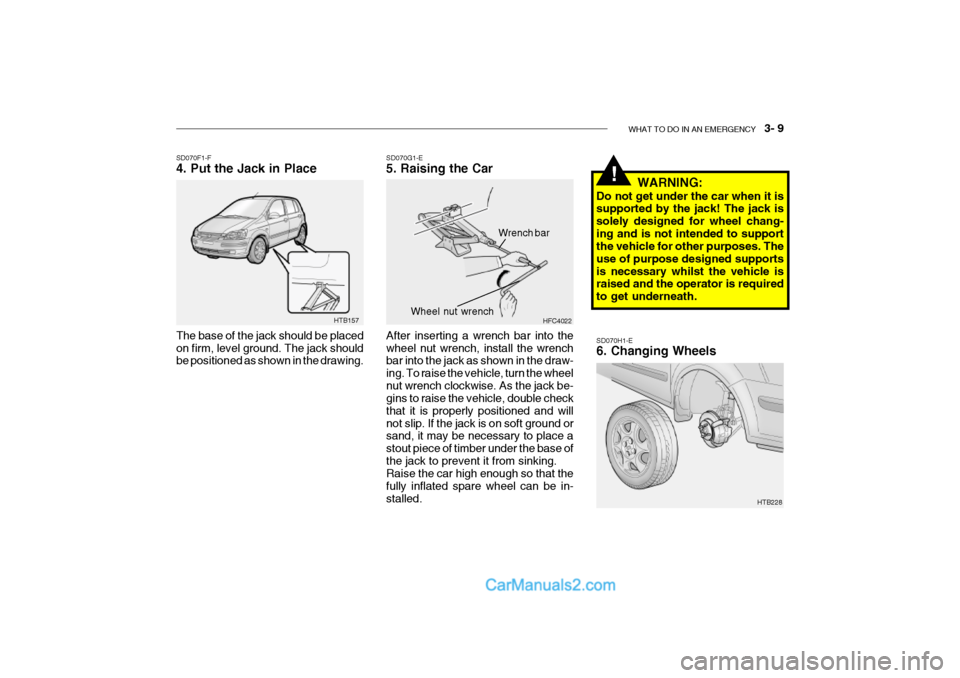
SD070F1-F 4. Put the Jack in Place The base of the jack should be placed on firm, level ground. The jack should be positioned as shown in the drawing.
SD070G1-E 5. Raising the Car After inserting a wrench bar into the wheel nut wrench, install the wrench bar into the jack as shown in the draw- ing. To raise the vehicle, turn the wheelnut wrench clockwise. As the jack be- gins to raise the vehicle, double check that it is properly positioned and willnot slip. If the jack is on soft ground or sand, it may be necessary to place a stout piece of timber under the base ofthe jack to prevent it from sinking. Raise the car high enough so that the fully inflated spare wheel can be in-stalled. HFC4022
Wrench bar
Wheel nut wrench
WARNING:
Do not get under the car when it is supported by the jack! The jack is solely designed for wheel chang-ing and is not intended to support the vehicle for other purposes. The use of purpose designed supportsis necessary whilst the vehicle is raised and the operator is required to get underneath.!
HTB228
Page 356 of 428

3- 10 WHAT TO DO IN AN EMERGENCY
HTB150
SD070J1-E 8. Lower Vehicle and Tighten
Nuts
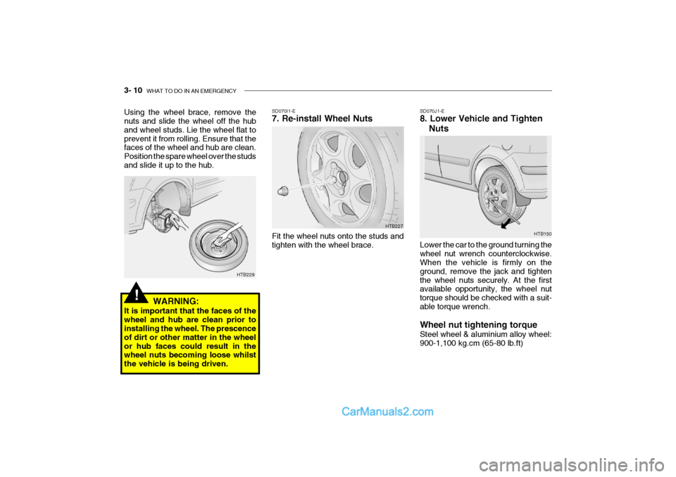
Lower the car to the ground turning the wheel nut wrench counterclockwise. When the vehicle is firmly on the ground, remove the jack and tightenthe wheel nuts securely. At the first available opportunity, the wheel nut torque should be checked with a suit-able torque wrench. Wheel nut tightening torque Steel wheel & aluminium alloy wheel: 900-1,100 kg.cm (65-80 lb.ft)
SD070I1-E 7. Re-install Wheel NutsFit the wheel nuts onto the studs and tighten with the wheel brace.
HTB227
Using the wheel brace, remove the nuts and slide the wheel off the hub and wheel studs. Lie the wheel flat toprevent it from rolling. Ensure that the faces of the wheel and hub are clean. Position the spare wheel over the studsand slide it up to the hub.
!
HTB229
WARNING:
It is important that the faces of the wheel and hub are clean prior to installing the wheel. The prescence of dirt or other matter in the wheelor hub faces could result in the wheel nuts becoming loose whilst the vehicle is being driven.
Page 357 of 428

WHAT TO DO IN AN EMERGENCY 3- 11
o OK FOR AUTOMATIC OR MANUAL
TRANSAXLE EQUIPPED VEHICLE WITH NO DAMAGE HTB208
HTB151B080A01TB-EAT VEHICLE TOWING OR RECOVERY
CAUTION:
An incorrect tow or recovery could result in serious damage to the ve-hicle. If any damage to the suspen- sion, steering or transaxle is appar- ent or suspected, a towing ambu-lance must be used. o OK FOR AUTOMATIC OR MANUAL
TRANSAXLE EQUIPPED VEHICLE
HTB207
!
SD070K1-E AFTER CHANGING WHEELS The pressure of the spare tyre should be checked at the first available oppor- tunity. If any doubt exists as to the tyre pressure, the vehicle should be drivenslowly to the nearest service station and the tyre pressure checked and adjusted as required.If the valve cap is lost from any of the valves, a replacement should be ob- tained and fitted at the first availableopportunity. The valve cap prevents the ingress of dirt which may cause the valve to stick and therefore leak and ispart of the valve sealing function. Ensure that the spare wheel, jack and wheel nut wrench as well tools are correctly located in the boot of thevehicle to prevent damage and noise.
The vehicle may be towed by the con-ventional method using the towing eye at the front of the vehicle as an attach- ment point. In addition, a suspendedtow with or without an ambulance may be used with either the front or the rear wheels being suspended, provided theabove caution is observed.
Page 359 of 428

WHAT TO DO IN AN EMERGENCY 3- 13
D120A01A-EAT IF YOU LOSE YOUR KEYS Information about the key of immobi- lizer system will be found on page 1-4.CAUTION:
If the car is being towed with allfour wheels on the ground, it can be towed only from the front. Besure that the transaxle is in neu- tral. Do not tow at speeds greater
than 30 mph (50 km/h) and for more
than 15 miles(25 km). Be sure the steering is unlocked by placing the key in the "ACC" posi- tion. A driver must be in the towed vehicle to operate the steering andbrakes.
!
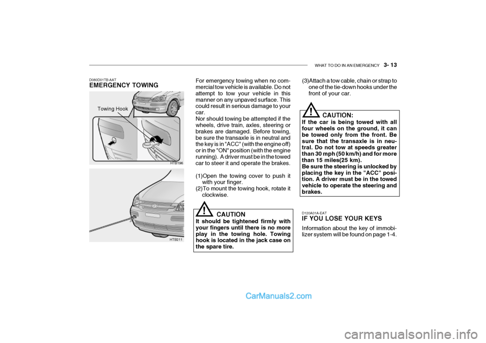
(3)Attach a tow cable, chain or strap to
one of the tie-down hooks under the front of your car.
D080D01TB-AAT EMERGENCY TOWING For emergency towing when no com- mercial tow vehicle is available. Do not attempt to tow your vehicle in thismanner on any unpaved surface. This could result in serious damage to your car.Nor should towing be attempted if the wheels, drive train, axles, steering or brakes are damaged. Before towing,be sure the transaxle is in neutral and the key is in "ACC" (with the engine off) or in the "ON" position (with the enginerunning). A driver must be in the towed car to steer it and operate the brakes. (1)Open the towing cover to push it
with your finger.
(2)To mount the towing hook, rotate it clockwise.
HTB196
HTB211 CAUTION
It should be tightened firmly with your fingers until there is no moreplay in the towing hole. Towing hook is located in the jack case on the spare tire.
!
Towing Hook
Page 369 of 428

VEHICLE MAINTENANCE REQUIREMENTS 5- 5
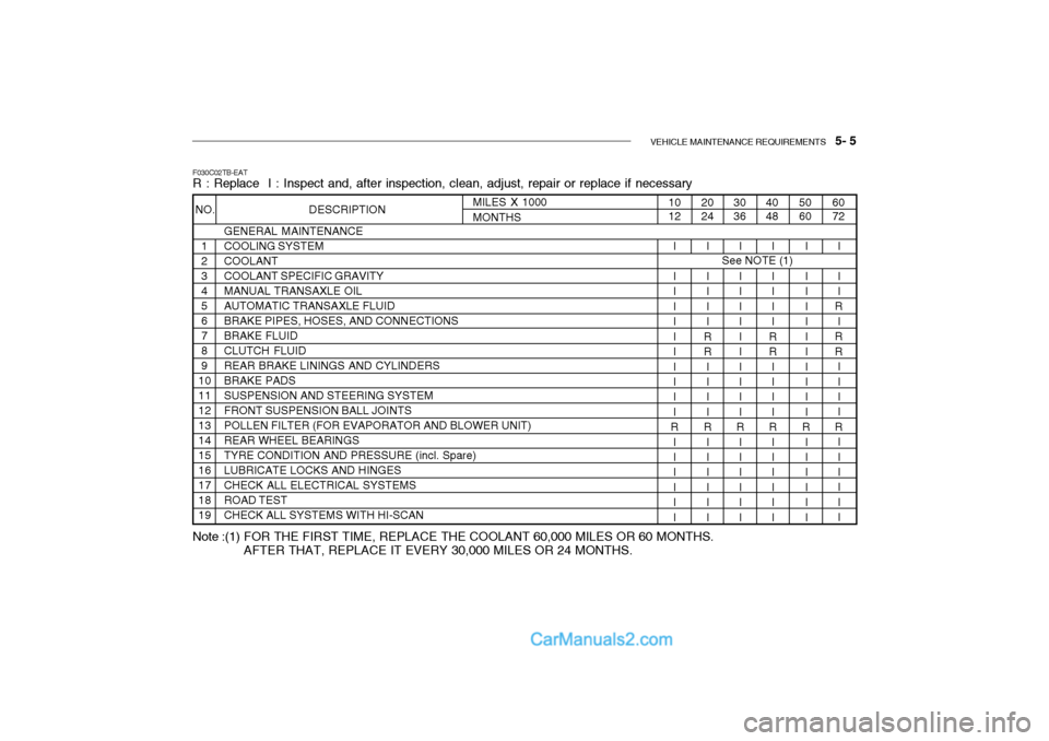
F030C02TB-EAT R : Replace I : Inspect and, after inspection, clean, adjust, repair or replace if necessary
GENERAL MAINTENANCE COOLING SYSTEMCOOLANTCOOLANT SPECIFIC GRAVITYMANUAL TRANSAXLE OILAUTOMATIC TRANSAXLE FLUIDBRAKE PIPES, HOSES, AND CONNECTIONSBRAKE FLUIDCLUTCH FLUIDREAR BRAKE LININGS AND CYLINDERSBRAKE PADSSUSPENSION AND STEERING SYSTEMFRONT SUSPENSION BALL JOINTSPOLLEN FILTER (FOR EVAPORATOR AND BLOWER UNIT)REAR WHEEL BEARINGSTYRE CONDITION AND PRESSURE (incl. Spare)LUBRICATE LOCKS AND HINGESCHECK ALL ELECTRICAL SYSTEMSROAD TESTCHECK ALL SYSTEMS WITH HI-SCAN
60 72
5060
4048
I I I
R
I
RR II I I
R III I II
I I I IIIII I II
R II I III
I I I II
RR I I II
R II I III
30 36
2024
I I I IIIII I II
R II I III
I I I II
RR I I II
R II I III
10 12
I I I IIIII I II
R II I III
MILES X 1000MONTHS
NO. DESCRIPTION
1 23456789
10111213141516171819
See NOTE (1)
Note :(1) FOR THE FIRST TIME, REPLACE THE COOLANT 60,000 MILES OR 60 MONTHS. AFTER THAT, REPLACE IT EVERY 30,000 MILES OR 24 MONTHS.
Page 401 of 428

DO-IT-YOURSELF MAINTENANCE 6- 27
5. Open the hood.
6. Draw the vertical line (through the
center of each headlight beam pat-tern) and the horizontal line (throughthe center of each headlight beam pattern) on the aiming screen. And then, draw the horizontal paral- lel line at 1.18 in. (30 mm ) under the horizontal line.
7. Adjust each cut-off line of the low beam to the parallel line with a phillipsscrewdriver - VERTICAL AIMING.
8. Adjust each cut-off line of the low
beam to each vertical line with aphillips screwdriver - HORIZONTAL AIMING. HTB269
Horizontal Aiming
Vertical Aiming
G290A01FC-EAT HEADLIGHT AIMING ADJUST- MENT Before performing aiming adjustment, make sure of the following.
1. Keep all tires inflated to the correct pressure.
2. Place the vehicle on level ground
and press the front bumper and rear bumper down several times. Place the vehicle at a distance of 118 in. (3,000 mm) from the test wall.
3. See that the vehicle is unloaded (except for full levels of coolant,engine oil and fuel, and spare tire,jack, and tools).
4. Clean the head lights lens and turn
on the headlight (low beam). WARNING:
Be sure to carefully wipe away anywater drained out in this manner,because the fuel mixed in the water might be ignited and result in a fire.!
1. Remove the engine cover.
2. Disconnect the air intake hose from air cleaner cover.
3. Loosen the drain plug at the bottom
of the fuel filter.
4. Tighten the drain plug when water no longer comes out.
5. Check to be sure that the warning
lamp illuminates when the ignition key is turned to "ON", and that it goes off when the engine is started.If in doubt, consult your nearest au- thorized HYUNDAI dealer.
G300B01FC
Page 408 of 428
6- 34 DO-IT-YOURSELF MAINTENANCE
G200C01TB-GAT FUSE PANEL DESCRIPTION Engine Compartment
HTB261-EPROTECTED COMPONENTS
Ignition Switch
Ignition Switch, Start Relay
Fuel pump, Alternator, ECM
Auto Fuel Cut Switch
Radiator Fan
Headlight, Defogger RelayABSECMA/CON, Fuel PumpInjectorA/Conditioner
HornABSABS
Blower, Blower Motor
Power Window
Electronic power steering AlternatorSpare Fuse Spare FuseSpare Fuse
FUSE RATING
30A30A30A20A30A50A10A10A10A15A10A10A20A40A30A30A50A 15A 10A10A
DESCRIPTION
IGN 2IGN 1ECU
F/PUMP RAD
BATT ABS
ECU
SNSR INJ
A/CON HORN ABS1ABS2 BLW
P/WDW EPS
BATT( ) SPARE
SPARE
SPARE
NOTE:
Not all fuse panel descriptions in this manual may be applicable to your vehicle. It is accurate at the time of printing. When you inspect the fuse box on your vehicle, refer to the fuse box label.
1.1L 1.3/1.6L 100A120A