2002 Hyundai Atos low beam
[x] Cancel search: low beamPage 158 of 249

FEATURES OF YOUR HYUNDAI 1-21
B340B01X-DAG
ZB120A1-E MULTI FUNCTION SWITCH Turn Signal Operation
To signal an intention to turn right, the switch
lever should be pulled down. To signal an intention to turn left, the switch lever should bepushed upwards. In both instances, the turnsignal lamps on one side of the car will flashand the warning lamp located in the instrumentcluster will flash in sympathy. Upon completionof the manoeuvre, the lever will, under normalcircumstances, return to the "Off" position.However, if the manoeuvre involved only asmall movement of the steering wheel, thesignal may need to be cancelled manually. Ifeither turn signal indicator flashes more rapidlythan normal or refuses to flash at all, a malfunc-tion of the turn signal system may exist.
ZB110U1-A SPEEDOMETER Your Hyundai’s speedometer is calibrated in
miles per hour (on the outer scale) and kilome- ters per hour (on the inner scale).
B300A01X-DAG
ZB110W1-E TRIP ODOMETER The trip odometer may be used to more accu-
rately record trip distances. Push the reset knob to set the counter to zero. ZB110V1-E ODOMETERThe odometer records the total driving distance
in miles, and is useful for keeping a record for maintenance intervals.
ZB120C1-A HEADLIGHT SWITCH
B340C01X-DAG
ZB120D1-E HIGH AND LOW BEAMTo turn on the headlight high beams, push the
lever forward (away from you). For low beams, pull the lever back (toward you). The appropri-ate headlight beam indicator light will come onat the same time.
To operate the headlights, turn the barrel on the
end of the multi-function switch. The first posi- tion turns on the parking lights, sidelights, taillights and instrument panel lights. The secondposition turns on the headlights.
Page 160 of 249
FEATURES OF YOUR HYUNDAI 1-23
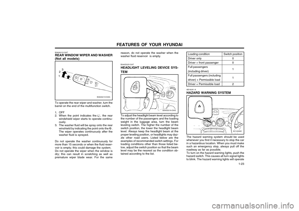
reason, do not operate the washer when the washer fluid reservoir is empty. B340G02X-GAT HEADLIGHT LEVELING DEVICE SYS- TEM To adjust the headlight beam level according to the number of the passengers and the loadingweight in the luggage area, turn the beamleveling switch. The higher the number of theswitch position, the lower the headlight beamlevel. Always keep the headlight beam at the
proper leveling position, or headlights may daz-zle other road users. Listed below are theexamples of recommanded switch settings. Forloading conditions other than those listed be-
low, adjust the switch position so that the beamlevel may be the nearest as the condition ob-tained according to the list.
B340G01A-DAG
B390A01X-GAT REAR WINDOW WIPER AND WASHER (Not all models)
B390A01X-DAG
To operate the rear wiper and washer, turn the barrel on the end of the multifunction switch.
1. OFF
2. When the point indicates the , the rear windshield wiper starts to operate continu-ously.
3. The washer fluid will be spray onto the rear winshield by indicating the point onto the .The wiper operates continuously after thewasher fluid is sprayed.
Do not operate the washer continuously formore than 15 seconds or when the fluid reser-voir is empty; this could damage the system. Do not operate the wiper when the window is dry; this can result in scratching as well aspremature wiper blade wear. For the same
1 2
3
The hazard warning system should be used
whenever you find it necessary to stop the car in a hazardous location. When you must makesuch an emergency stop, always pull off theroadway as far as possible.
To turn on the hazard warning lights, push the
hazard switch. This causes all turn signal lightsto blink. The hazard warning lights will operate AB160A1-A HAZARD WARNING SYSTEM
XV10590E
Loading condition Driver only Driver + front passenger Full passengers(including driver)Full passengers (including driver) + Permissible load Driver + Permissible load
Switch position
0 0 1 1 2
Page 235 of 249

DO-IT-YOURSELF MAINTENANCE 6-17
WARNING: The halogen bulb contains gas under pres-
sure and if impacted could shatter, and re- sulting in flying fragments. Always wear eye
protection when servicing the bulb. Protectthe bulb against abrasions or scratches andagainst liquids when lighted. Turn on thebulb only when installing in a headlight.Replace the headlight if damaged or cracked.Keep the bulb out of the reach of childrenand dispose of the used bulb with care.
G290A01X-EAT
HEADLIGHT AIMING ADJUSTMENT
G290A01V
Before performing aiming adjustment, make sure
of the following.
Vertical aiming
1. Keep all tires inflated to the correct pres- sure.
2. Place the vehicle on level ground and press the front bumper & rear bumper down sev- eral times.
3. See that the vehicle is unloaded (except for full levels of coolant, engine oil and fuel, andspare tire, jack, and tools). Have the driveror equivalent weight placed in driver's seat.
4. Clean the head lights lens and turn on the headlight (Low beam).
5. Open the bonnet.
6. Draw the vertical line (through the center of each headlight) and the horizontal line(through the centre of each headlight) on theaiming screen.
1) Horizontal line dimension from ground:25.43 in. (646 mm)
2) Distance between each vertical line: 38.89 in. (988 mm)And then, draw the parallel line at 1.18 in. (30 mm) place under the horizontal line.
7. Adjust each cut-off line of the low beam to the parallel line with a phillips screwdriver -VERTICAL AIMING
8. Adjust each cut-off line of the low beam to the each vertical line with a phillips screw-driver - HORIZONTAL AIMING. G290B01X-EAT
Adjustment After Headlight Assembly Replacement
If the vehicle has had front body repair and the headlight assembly has been replaced, theheadlight aiming should be checked using theaiming screen as shown in the illustration. Turnon the headlight switch. (Low Beam Position)
1. Adjust headlights so that main axis of light is parallel to centre line of the body and isaligned with point "P" shown in the illustra-tion.
2. Dotted lines in the illustration show centre of headlights. G290B01S-DAG
Horizontal lineVertical line
W
0.59 in.
"P" 1.18 in.
Cut-off line
Ground line H
H L
Page 248 of 249

INDEX
10-2
FRONT FOG LIGHT
SWITCH ......................................................... 1-29
FUEL ECONOMY ............................................................................... 2-3
FUEL GAUGE .................................................................................. 1-20
FUEL RECOMMENDATIONS ........... ................................................. 1-1
FUSIBLE LINKS ............................................................................... 6-14
G GENERAL CHECKS .......................................................................... 6-2
H
HAZARD WARNING SYSTEM ........................................................ 1-24
HEADLIGHT BULB ........................................................................... 6-16
HEADLIGHT LEVELING DEVICE SYSTEM ....................................1-23
HEADRESTRAINT .............................................................................. 1-5
HEADLIGHT FLASH ER .................................................................... 1-22
HEADLIGHT SWITCH ...................................................................... 1-21
HEATED REAR WINDOW ................... ............................................1-24
HEATING AND VENTILATION ........................................................ 1-32
HIGH AND LOW BEAM ................................................................... 1-21
HIGH-MOUNTED REAR STOPLIGHT .............................................1-27
HORN ............................................................................................... 1-32
IIF THE ENGINE CANNOT BE CRANKED ........................................ 3-1
IF THE ENGINE OVERHEATS .......................................................... 3-2
IF THE ENGINE WILL NOT START .................................................. 3-1
IGNITION SWITCH ............................................................................. 2-2
IMMOBILIZER SYSTEM ..................................................................... 1-2INDIVIDUAL CIRCUIT FUSES ......................................................... 6-15
INSTRUMENT CLUSTER AND INDICATOR ..................................1-17INSTRUMENTS AND CONTROLS
..................................................1-16
INTERIOR LIGHT ............................................................................. 1-25
JJUMP STARTI NG ........................................................................ 3-1~3-2
KKEY POSITIONS ................................................................................ 2-2
KEYS .................................................................................................. 1-2 L LIGHT BULBS .................................................................................. 6-16
LIMP HOME PROCEDURES ............................................................. 1-2
LOW FUEL LEVEL WARNING LAMP .............................................1-19
M
MAINTENANCE AND SERVICING REQUIREMENTS ..................... 5-1
MAINTENANCE UNDER SEVERE USAGE CONDITIONS .............. 5-4
MANUAL TRANSAXLE LUBRICANT ................................................. 6-9
MANUAL TRANSAXLE ...................................................................... 2-4
MULTI FUNCTION SWITCH ................................. ...........................1-21
OODOMETER ..................................................................................... 1-21
OIL PRESSURE WARNING LIGHT ................................................. 1-18
OUTSIDE REAR VIEW MIRROR ....................................................1-25
PPARKING BRAKE ............................................................................ 1-26
POWER STEERING FLUID LEVEL ................................................. 6-16