2002 HONDA CIVIC height
[x] Cancel search: heightPage 610 of 1139

Master Cylinder Replacement
NOTE: Do not spill brake fluid on the vehicle; it may
damage the paint; if brake fluid does contact the paint,
wash it off immediately with water,
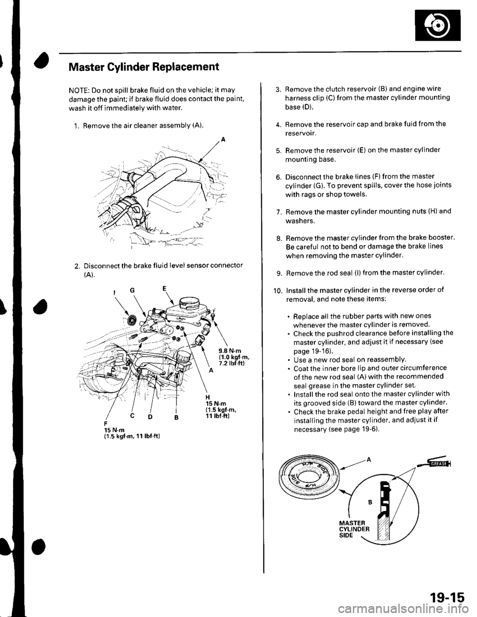
1, Remove the air cleaner assembly (A).
2, Disconnect the brake fluid level sensor connector
(A).
15 N.m{1.5 kgt.m, 11 lbt.ft)
3. Remove the clutch reservoir (B) andenginewire
harness clip (C)from the master cylinder mounting
base (D).
4. Remove the reservoir cap and brake fuid from the
reservoir.
5. Remove the reservoir (E) on the master cylinder
mountrng Dase.
6, Disconnect the brake lines (F)from the master
cylinder (G). To prevent spills, cover the hose joints
with rags or shop towels.
7. Remove the master cylinder mounting nuts {H) and
washers.
8. Remove the master cylinder from the brake booster.
Be careful not to bend or damage the brake lines
when removing the master cylinder.
9. Remove the rod seal (l) from the master cylinder.
10. Installthe master cylinder in the reverse order of
removal, and note these items:
. Replace all the rubber parts with new ones
whenever the master cylinder is removed.
. Check the pushrod clearance before installing the
master cylinder. and adjust it if necessary (see
page 19-16).. Use a new rod seal on reassemblY. Coat the inner bore lip and outer circumference
of the new rod seal {A) with the recommended
seal grease in the master cylinder set.
. Installthe rod seal ontothe master cylinder with
its grooved side (B)toward the master cylinder.
. Check the brake pedal height and free play after
installing the master cylinder, and adjust it if
necessary (see page 19-6).
19-15
Page 613 of 1139

Gonventional Brake Components
IBrake Booster Test
Functional Test
1. With the engine stopped, press the brake pedal
several times to deplete the vacuum reservoir, thenpress the pedal hard, and hold itfor 15 seconds. lfthe pedal sinks, either the master cylinder is
bypassing internally, or the brake system (master
cylinder, lines. modulator, or calipers) is leaking.
2. Start the engine with the brake pedal pressed. lf thepedal sinks slightly, the vacuum booster is workingproperly. lf the pedal height does not vary, thebooster or check valve is faulty.
3. With the engine running, press the brake pedal
lightly. lfthe brake pedal sinks more than 1O mm
{3/8 in, ) in 3 minutes, the master cylinder is faulty.A slight change in pedal height when the Ay'C
compressor cycles on and off is normal. (The A,/C
compressor load changes the vacuum available tothe booster.)
Leak Test
1. Press the brake pedal with the engine running, thenstop the engine. lf the pedal height does not vary
while pressed for 30 seconds, the vacuum boosteris OK. lf the pedal rises, the booster is faulty.
2. With the engine stopped, press the brake pedal
several times using normal pressure. When thepedal is first pressed, it should oe row.
On consecutive applications, the pedal height
should gradually rise. lfthe pedal position does notvarv, check the booster check valve.
19-18
3. Disconnect the brake booster vacuum hose (check
valve built-in) (A) at the booster side.
5.
4.Start the engine, and let it idle. There should bevacuum available. lf no vacuum is available, thecheck valve is not working properly. Repiace thebrake booster vacuum hose and check valve, andrelesI.
Reconnect the brake booster vacuum nose.
Start the engine, and then pinch the brake boostervacuum hose between the check valve and thebooster,
Turn the ignition switch OFF, and wait 30 seconds,Press the brake pedal several times using normalpressu re,
When the pedal is first pressed, it should be low.On consecutive applications, the pedal height
should gradually rise.
. lf the pedal position does notvary, replacethe
brake booster.. lf the pedal position varies, replace the brake
booster vacuum hose/check valve assembly.
Page 614 of 1139

Brake Booster Replacement
1.Remove the master cylinder (see page 19-15).
Remove the master cylinder brake lines {A) from
the brake line clip.
c
6x1.0mm9.8 N.m(1.0 kgf.m,7.2 tbf.ft)
Remove the vacuum hose mounting bracket (B).
Disconnect the vacuum hose {C) from the brake
booster.
'-/
.,.,....
alu
i '..
5. Remove the clip (A) and the joint pin (B). and
disconnectthe yoke from the brake pedal.
7.
{'l.3 kgf.m,9 lbf.ftl
Remove the brake booster mounting nuts (C).
Remove the brake booster (A)from the engine
comparlmenr.
INdAdEI. Be careful not to damage the booster
surfaces and threads of the booster stud
bolts.. Be careful not to bend or damage the
brake lines.
lnstallthe brake booster in the reverse order of
removal, and note these items:
. Adjust the pushrod clearance before installing
the brake booster (see page 19-16).. Use a new clip whenever installing.. After installing the brake booster and master
cylinder, fill the reservoir with new brake fluid,
bleed the brake system (see page 19-8), and
adjust the brake pedal height and free play (see
page 19-6),
19-19
Page 654 of 1139

Body
DoorsComponent Location Index ...........Door Panel Removal/lnstallation .....,..........Door Outer Handle ReplacementDoor Latch ReplacementDoor Glass and RegulatorReplacementDoor Sash Trim Replacement .......................
Door Glass Outer WeatherstripReplacement
Door Weatherstrip Beplacement
Door Glass Adjustment .................................Door Position Adjustment .............................Door Striker Adiustment ................................MirrorsComponent Location Index ...........................Power Mirror Replacement ...........................Mirror Holder Replacement ...........................Rearview Mirror Rep1acement ......................
GlassComponent Location Index ...........................Windshield Replacement
Bear Window Rep1acement ...........................
Ouarter Glass Replacement ..........................MoonroofComponent Location Index ...........................Symptom Troubleshooting Index
Glass Height Adjustment ...............................
Glass ReplacementWind Def lector 8ep1acement ........................Drain Channel Rep1acement ..........................Sunshade Replacement .................................Motor ReplacementFrame and Drain Tube Replacement ............Drain Channel Slider and Cable AssemblyReplacementLimit Switch Adjustment ...............................Closino Force and ODenina Draq Check ......lnterioi TrimComponent Location Index ...........................Trim Removal/lnstallation DoorArea ..........Trim Removal/lnstallation-Rear Side AreaTrim Removal/lnstallation-Cargo Floor AreaTrim Removal/lnstallation-Hatch Area .........Headliner Removal/lnstallation* Carpet Rep1acement .......................................ConsolesConsoles, Front and RearRemova l/lnsta llationFront Console Disassembly/Reassembly .....
20-220,420-620-7
20-920 t0
20- 10
20-1120-1120-1220 13
20-1420-1520-1520-16
20 1120-1920-2520-29
20,3520-3620-3720-3120-3820 3920-4020-4120,42
20 4420-4620,44
20-4920 50
20-51
DashboardInstrument Panel Removal/lnstallation ........Driver's Dashboard Lower CoverRemovat InstallationDriver's Dashboard Under CoverRemova t Insta llation
Oriver's Pocket Removal/lnstallation ............Shift Lever Trim Removal/lnstallation ..........Center Panel Removal/lnstallation ...............Passenger's Dashboard Lower CoverRemova l/lnsta llat ionx Glove Box Removal/lnstallationDashboard Side VentRemoval/lnstallation .................................. 20-64Beverage Holder Removal/lnstallation ........ 20-64Driver'sTray Removal/lnstallation ............... 20-65Passenger's Tray Removal/lnstallation ........ 20 65* Dashboard Removal/lnstallation .................. 20-66Steerinq Hanqer Beam Reolacement ........... 20-68Seats "
Component Location Index ........................... 20-10* Front Seat Removal/lnstallation ................... 20-11* Front Seat Disassembly/Reassembly-Driver's .................................. 20-73* Front Seat Disassembly/Reassembly-Passenger's ........................... 20-74* Front Seat Cover Replacement ..................... 2O-75Rear Seat Removal/1nsta11ation ..................... 20-80Rear Seat-back Latch Replacement .............. 20-81Rear Seat-backStriker Replacement ............ 20-81
20-59
20-59
Rear Seat-back Cover Replacement ............. 20-82Rear Seat Cushion Cover Replacement ....... 20.84BumpersFront Bumper Removal/lnstallation .............Rear Bumoer Removal/lnstallation ...............HoodAdjustmentHood Seal ReplacementHood Insulator Rep1acement .........................Hatch
20-6020,6020 6120-62
20-63
20-63
20,8520-86
20-4720,8820,89
20-5220-5320-5420-55
20-5720-58
Adjustment ................... 20-90Hatch Suppon Strut Replacement ................ 20-91Hatch WeatherstriD Reo1acement ................. 20-92
Fuel Fill DoorAdiustment ................... 20-93Exterior TrimFront Grille Replacement ..............Cowl Covers Replac"rn""t .. . .....................A pillar Corner Trim Replacement ................Roof lMolding Replacement ...........................Rear License Trim ReplacementHatch Spoiler 8ep1acement ...........................Emblem Rep1acement .........................
20-9420-9520-9620-9720,9820-9920-100
Page 689 of 1139

Moonroof
Component Location Index
WIND DEFLECTORReplacement, page 20-38
GLASSHeight Adjustment, page 20 37Replacement, paqe 20-37Closino Force and Ooenino DraoCheck; page 20-48 "
DRAIN CHANNELReplacement, page 20-39
,5
?a<&,
@
..t'- ?.@-@c
_a
@
/,BR^CKEI
COVER
LIMIT SWITCH(AUTO.STOP SWITCH)Adjustment, page 20-46ER
I
CABLE TUBEREAR BRACKETE@
E STOP
.a'
MOONROOFCONTROL UNIT
FRAMEReplacement, page 20-42
CABLE ASSEMBLYBeplacement, page 20-44
*\
)REAR DRAIN VAI-VE
_-""-\q
Replacement, page 20'41
gJ -.- REAR DRA'N TUBE
20-35
Page 690 of 1139

Moonroof
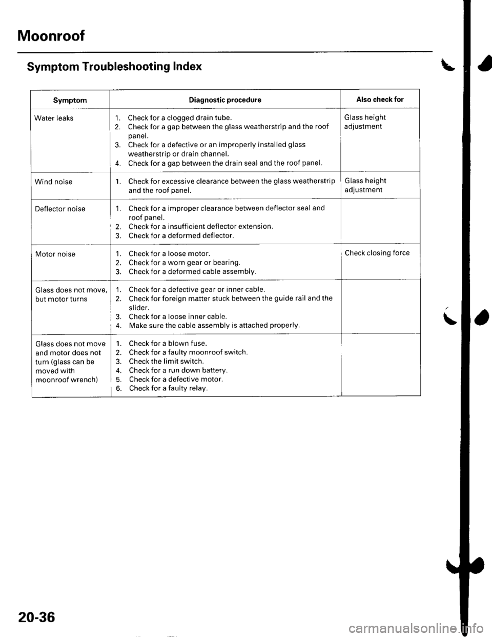
Symptom Troubleshooting Index
SymptomDiagnostic procedureAlso check for
Water leaks'1. Check for a clogged drain tube.
2. Check for a gap between the glass weatherstrip and the roof
panel.
3. Check for a defective or an improperly installed glass
weatherstrip or drain channel.
4. Check for a gap between the drain seal and the roof panel.
G lass height
adJustment
Wind nolse1. Check for excessive clearance between the glass weatherstrip
and the root panel.
Glass height
adjustment
Deflector noise1. Check for a imDrooer clearance between deflector seal and
roof panel.
2, Check for a insufficient deflector extension.
3. Check for a deformed deflector.
Motor noise1. Check for a loose motor.
2. Check for a worn gear or bearing.
3. Check for a deformed cable assembly.
Check closing force
Glass does not move,
but motor turns
1. Check for a defective gear or inner cable.
2. Check for foreign matter stuck between the guide rail and the
slide r.
3. Check for a loose inner cable.
4. l\,4ake sure the cable assembly is attached properly.
Glass does not move
and motor does nol
turn (glass can be
moved with
moonroof wrench)
1. Check for a blown fuse.
2. Check for a faulty moonroof switch.
3. Check the limit switch.
4. Check for a run down battery.
5. Check for a defective motor.
6. Check for a faulty relay.
20-36
Page 691 of 1139

Glass Height Adjustment
The roof panel (A) should be even with the glass
weatherstrip (B). to within 2*0.5/ 1 mm (0.08+0.02l
0.04 in.) all the way around. lf not, make the following
adjustment:
B
2 + 0.5/ 1mm{0.08 + 0.02/-0.0i1 in.}
2.
1,
\o
Remove the bracket cover from each side.
Loosen the nuts {A), and installthe shims (B)
between the glass frame (C) and glass bracket (D)
on each side.
Shim ihickness: Front and rear max. 2 mm 10.08 in.l
Forward
A6x1.0mmI N.m (0.9 kgf.m,7 lbt.ft)
3. lf necessary, repeat on the opposite side.
B
\
Glass Replacement
'LClose the glass fully.
Slide the sunshade allthe way back.
Remove the screws (A), then remove both bracket
covers (B). Remove the nuts (C) and shims {D) from
both glass brackets (E).
Fastengr Locations
cO,
6x1.0mm9 N.m {0.9 kgf.m, 7 lbf.ft}
4. Remove the glass {A) by lifting it up. Do not
damage the roof panel.
5. Install the glass in the reverse order of the removal,
and adjust the glass height alignment.
6. Check for water leaks. Use free-flowing water from
a hose without a nozzle. Do not use high-pressure
water.
Nut. il
@
A}:Screw, 2
E
20-37
Page 693 of 1139

1.
2.
Drain Channel Replacement
Remove the moonroof glass (see page 20-37).
With the moonroof wrench, move both glass
brackets (A) to the position where the moonroof
normally pivots down, and remove the screws
securing the drain channel (B).
Fastener Locations
) : Screw, 2
@
Release the drain channel (A) from both hooks {B)
of the drain channel slider by pulling the drain
channel forward,
4. Remove the drain channel (A).
Installthe channel in the reverse order of removal,
and note these items:
Push the drain channel onto the hooks until a
faint click is heard.
Check the glass height adjustment (see page 20-
31).
Check for water leaks. Let the water run freely from
a hose without a nozzle. Do not use a high-pressure
spray.
20-39