Page 815 of 1139

Heating and Air Conditioning
Heater Unit/Core Replacement (cont'd)
8. Remove the dashboard {see page 20-66).
9. Disconnectthe connectors (A) from the blower
motor, the recirculation control motor, the mode
control motor, and the power transistor, then
remove the wire harness clips (B) and the
connector (C). Remove the self-tapping screws and
the bracket (D).
Disconnect the connectors (A) from the evaporator
temperature sensor and the air mix control motor,
then remove the wire harness clips (B) and the
connector (C). Remove the self-tapping screw and
the cover (D). Disconnect the heater valve cable (E).
10,
7t,
21-44
11. Remove the mounting bolts, the mounting nuts,
and the heater unit.
Remove the self-tapping screws and the expansion
valve cover (A). Carefully pull out the evaporator
core (B) so you don't bend the inlet and outlet pipes.
Remove the grommet (C), then remove the self-
tapping screws and the flange cover (D). Bemove
the self-tapping screws and the pipe cover (E), then
carefully pull out the heater core (F) so you don't
bend the inlet and outlet oioes.
@
5x 1.0 mm9.8 N.m11.0 kgl m,7.2 tbf.ftl
12.
Page 817 of 1139
Heating and Air Conditioning
Heater Valve Cable Adjustment
1. From underthe hood, open the cable clamp {A),
then disconnect the heater valve cable (B) from the
heater valve arm {C).
tFrom under the dash, disconnect the heater valve
cable housing from the cable clamp (A), and
disconnect the heater valve cable (B) from the air
mix control linkage {C).
, t.- l
\'r2t' ''' '
' ::"'
Set the temperature control dial on Max Cool with
the ignition switch ON (ll).
Attach the heater valve cable (B) to the air mix
control linkage (C) as shown above, then snap the
heater valve cable housing into the cable clamp (A).
.'.-:',,
-"ll
.....-
21-46
5, From under the hood, turn the heater valve arm {C)
to the fully closed position as shown, and hold it.
Attach the heater valve cable (B) to the heater valve
arm, and gently pull on the heater valve cable
housing to take up any slack, then install the heater
valve cable housing into the cable clamp (A).
.
\
Page 819 of 1139

Heating and Air Gonditioning
1.
Compressor Clutch Check
Check the armature plate for discoloration, peeling,
or other damage. lf there is damage, replace the
clutch set (see page 21-49),
Check the rotor pulley bearing play and drag by
rotating the rotor pulley by hand. Beplace the
clutch set with a new one if it is noisy or has
excessive play/drag (see page 21-49).
Measure the clearance between the rotor pulley (A)
and the armature plate (B) all the way around. lf the
clearance is not within specified limits, remove the
armature plate (see page 21-49) and add or remove
shims as needed to increase or decrease clearance.
Clearance: 0.510.15 mm {0.02010.006 in.)
NOTE: The shims are available in four thicknesses:
0.1 mm.0.2 mm,0.4 mm, and 0.5 mm.
21-48
a
4. Release the field coil con nector f rom the holder,
then disconnect it. Check the thermal protector for
continuity. lf there is no continuity, replace the
thermal protector (see page 21-51).
NOTE: The thermal Drotector will have no
continuity above 252to270"F \122lo 132'C). When
the temperature drops below 241 to 219'F (116 to
104'C), the thermal protector will have continuity.
Check resistance of the field coil. lf resistance is not
within specifications, replace the field coil
(see page 21-49).
Field Coil Resistance: 3.05 3.35ohmsat68"F
t20"c)
,\.
Page 821 of 1139
Heating and Air Gonditioning
Compressor Clutch Overhaul (cont'd)
5. Reassemble the clutch in the reverse order of
disassembly, and note these items:
. Installthe field coil with the wire side facing
down, and align the boss on the field coil with the
hole in the compressor.. Clean the rotor pulley and compressor sliding
surfaces with contact cleaner or other
non-petroleum solvent..Install new snap rings, note the installation
direction, and make sure they are fully seated in
the groove.
. Make sure that the rotor pulley turns smoothly
after it's reassembled,. Route and clamp the wires properly or they can
be damaged by the rotor pulley.
21-50
Page 823 of 1139

Heating and Air Conditioning
Gondenser Replacement
1.
6x1.0mm9.8 N.m ('1.0 kgf.m,7.2lbf.ft)
Recover the refrigerant with a recovery/recycling/
charging station (see page 21-53).
Remove the front bumper {see page 20-85).
Remove the bolts, then disconnect the discharge
line (A) and the condenser line (B) from the
condenser. Plug or cap the lines immediately after
disconnecting them to avoid moisture and dust
conlamtnaflon.
,t\
6x1.0mm9.8 N.m (1.0 kgt.m.7.2lbf.ft)
21-52
4, Remove the mounting bolts, then remove the
condenser by lifting it up. Be careful not to damage
the radiator or the condenser fins when removino
the condenser.
6 x '1.0 mm9.8 N.m ('1.0 kgf.m,7.2 tbl.ftl
5.lnstallthe condenser in the reverse order of
removal, and note these items.
. lf you're installing a newcondenser, add
refrigerant oil (KElHlN SP- 10) lsee page 21'6).. Replace the O-rings with new ones at each fitting,
and apply a thin coat of refrigerant oil before
installing them. Be sure to use the correct O-rings
for HFC-134a (R-'134a)to avoid leakage.. lmmediately after using the oil, reinstallthe cap
on the container, and seal it to avoid moisture
absorption.. Do not spillthe refrigerant oil onthevehicle;it
may damage the paint. lf the refrigerant oil
contacts the paint, wash it off immediately.. Be careful not to damage the radiator or the
condenser fins when installing the condenser.. Charge the system (see page 21-55).
t -"'.
f,
t-
-li .:)-:.-- ---- - -'
Page 825 of 1139

Heating and Air Conditioning
System Evacuation
Use only service equipment that is U.L.-listed and is
certified to meet the requirements of SAE J2210 to
remove HFC-134a (R-134a)from the air conditioninq
system.
lf accidental system discharge occurs, ventilate the
work area before resuming service.
Additional health and safety information may be
obtained from the refrigerant and lubricant
manufacturers.
1. When an Ay'C system has been opened to the
atmosphere, such as during installation or repair, it
must be evacuated using a R-134a refrigerant
recovery/recycling/charging station (lf the system
has been open for several days, the receiver/dryer
should be replaced, and the system should be
evacuated for several hours.)
. Air conditioning refrigerant or lubricant vapor
can irritate your eyes, nose, or throat.. Be carefulwhen connecting service equipment.. Do not breathe refrigerant or vapor.
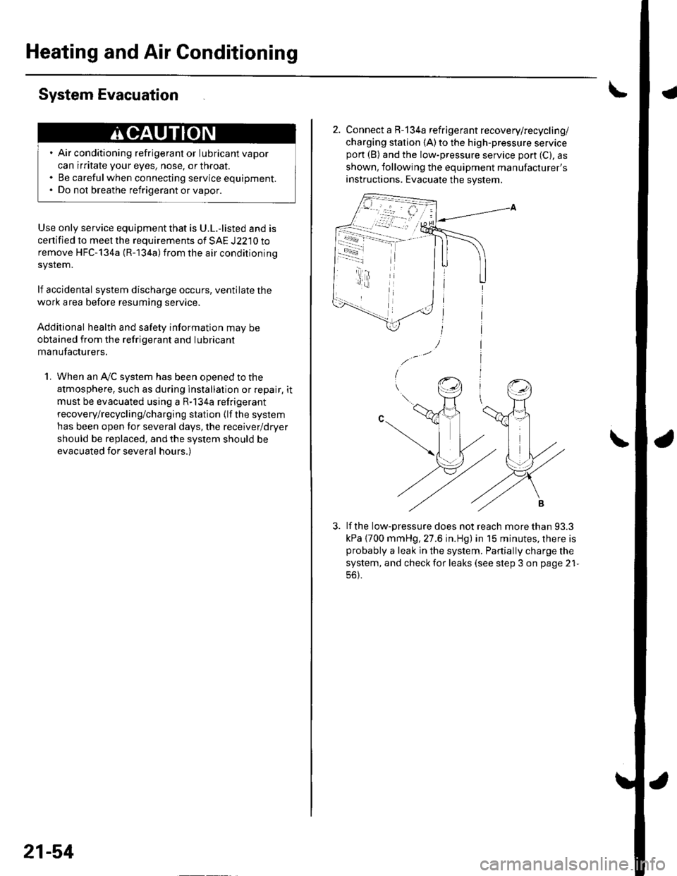
21-54
2. Connect a R-134a refrigerant recovery/recycling/
charging station (A)to the high-pressure servicepon (B) and the low-pressure service port (C), as
shown, following the equipment manufacturer's
instructions. Evacuate the system.
lf the low-pressure does not reach more than 93.3
kPa {700 mmHg, 27.6 in.Hg) in 15 minutes, there isprobably a leak in the system. Partially charge the
system, and check for leaks (see step 3 on page 21-
56).
-i - r4.t
Page 827 of 1139

Heating and Air Conditioning
Refrigerant Leak Test
Special Tool Required
Leak detector, Honda Tool and Equipment YGK-H-10PM
commerciallv available
Compressed air mixed with R-134a forms a
combustible vapor.
The vapor can burn or explode causing serious
injury.
Never use compressed air to pressure test
R-134a service equipment or vehicle air
conditioning system.
Air conditioning refrigerant or lubricant vapor
can irritate your eyes, nose, or throat.
Be carefulwhen connecting service equipment.
Do not breathe refrigerant or vapor
Use only service equipment that is U.L.-listed and is
certiified to meet the requirements of SAE J2210 to
remove HFC-134a (R-134a) from the air conditioning
system.
lf accidental system discharge occurs, ventilate the
work area before resuming service.
R-134a service equipment or vehicle air conditioning
systems should not be pressure tested or leak tested
with compressed air.
Additional health and safety information may be
obtained from the refrigerant and lubricant
manufacturers.
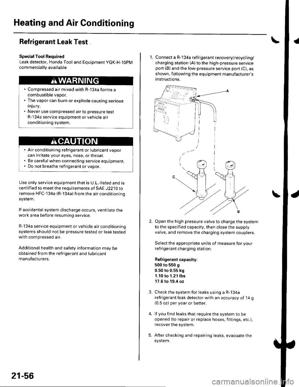
21-56
1. Connect a R-134a refrigerant recovery/recycling/
charging station (A) to the high-pressure serviceport (B) and the low-pressure service port (C), as
shown, following the equipment manufacturer's
anstructions.
Open the high pressure valve to charge the system
to the specified capacity, then close the supply
valve, and remove the charging system couplers.
Select the appropriate units of measure for your
refrigerant charging station.
Refrigerant capacity:
500 to 550 g
0.50 to 0.55 kg
1.10 to 1.21 lbs
17.6 to 19.4 oz
Check the system for leaks using a R-134a
refrigerant leak detector with an accuracy of 14 g(0.5 oz) per year or better.
lf you find leaks that require the system to be
opened (to repair or replace hoses, fittings, etc.),
recover the system.
After checking and repairing leaks, evacuate the
system.
3.
Page 829 of 1139

Heating and Air Conditioning
A/C System Tests (cont'd)
1.
Performance Test
Air conditioning refrigerant or lubricant vapor
can irritate your eyes, nose, or throar.
Be carefulwhen connecting service equipment.
Do not breathe refrigerant or vapor.
The performance test will help determine if the air
conditioner system is operating within specifications.
Use only service equipment that is U.L.-listed and is
cenified to meet the requirements of SAE J2210 toremove HFC-134a (R-134alfrom the air conditioning
system.
lf accidental system discharge occurs, ventilate the
work area before resuming service
R-134a service equipment or vehicle air conditioning
systems should not be pressure tested or leak testedwith compressed air.
Additional health and safety information may be
obtained from the refrigerant and lubricant
manufacturers.
Connect a R-134a refrigerant recover/recycling/
charging station to the high-pressure service port
and the low-pressure service port, following the
equipment manufacturer's instructions.
Determine the relative humidity and air
Iemperaru re.
' Compressed air mixed with R-134a forms a
combustible vapor.. The vapor can burn or explode causing serious
Injury.. Never use compressed air to pressure test
R-134a service equipment or vehicle air
conditioning systems.
21-58
4.
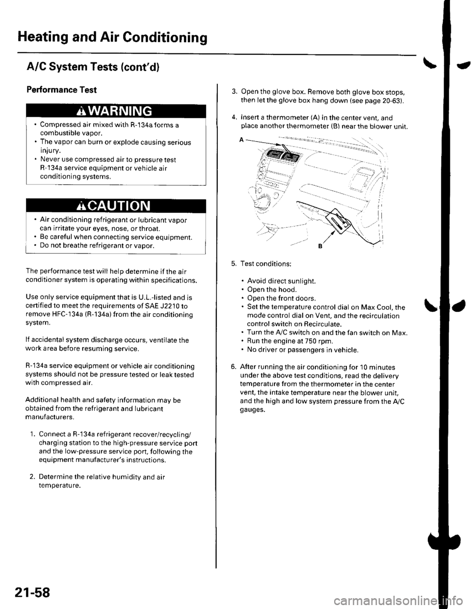
Open the glove box. Remove both glove box stops,
then let the glove box hang down (see page 20-63).
Insert a thermometer (A) in the center vent, andplace another thermometer {B) near the blower unit.
Test conditions:
. Avoid direct sunlight.. Open the hood.. Open the front doors.. Sel the temperature control dial on Max Cool, the
mode control dial on Vent, and the recirculation
control switch on Recirculate.. Turn the A,/C switch on and the fan switch on Max.. Run the engine at 750 rpm.. No driver or passengers in vehicle.
After running the air conditioning for I0 minutes
under the above test conditjons, read the delivery
temperature from the thermometer in the center
vent, the intake temperature near the blower unit,
and the high and low system pressure from the Ay'Cga uges.