Page 138 of 1139
9.
10.
Install the four ignition coils (see page 4-'18).
Check that all tubes, hoses, and connectors are
installed correctly.
lnstallthe intake manifold cover.11.
6x 1,0 mm'12 N.m {1.2 kgf m.8.7 tbf.ftl
12. After assemblv, wait at least 30 minutes before
filling the engine with oil.
6-43
Page 144 of 1139
Engine Block
Crankshaft Main Bearing Replacement
Main Bearing Clearance Inspection
1. To check main bea ring-to-jou rna I oil clearance.
remove the lower block and bearing halves (see
page 1 -12)..
2, Clean each main journal and bearing half witha
clean shop towel.
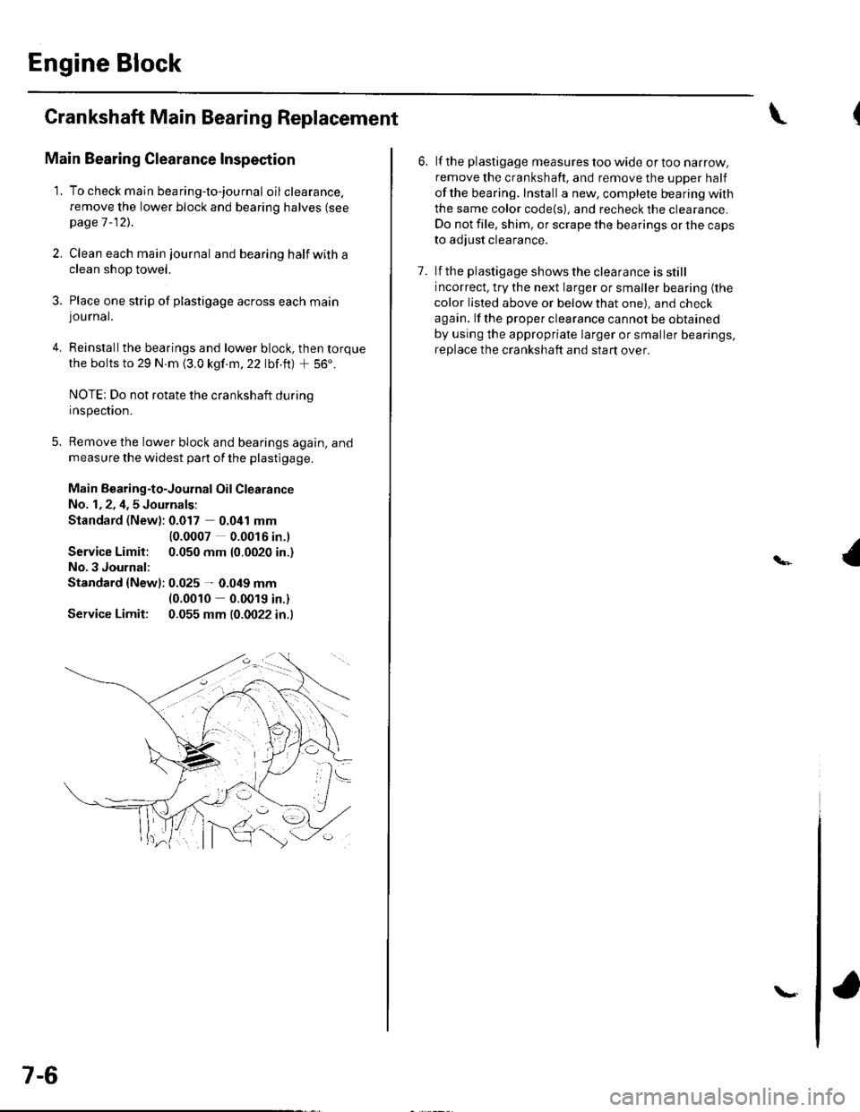
3. Place one strip of plastigage across each main
lou rnal.
4. Reinstallthe bearings and lower block, then torque
the bolts to 29 N.m {3.0 kgf.m,22 lbf.ft) + 56'.
NOTE: Do not rotate the crankshaft during
Inspeclton.
5. Remove the lower block and bearings again, and
measure the widest part of the plastigage.
Main Bearing-to-Journal Oil Clearance
No. 1,2, 4,5 Journals:
Standard (New): 0.017 0.041 mm
Service Limit:
No.3 Journal:
10.0007 0.0016 in.l
0.050 mm {0.0020 in.)
Standard {Newl: 0.025 - 0.049 mm(0.0010 0.0019 in.)
Service Limit: 0.055 mm (0.0022 in.l
7-6
\.
6. lf the plastigage measures too wide or too narrow,
remove the crankshaft. and remove the upper half
ofthe bearing. Install a new, complete bearing with
the same color code{s), and recheck the clearance.
Do not file, shim, or scrape the bearings or the caps
to adjust clearance.
7. lf the plastigage shows the clearance is still
incorrect, try the next larger or smaller bearing (the
color listed above or below that one), and check
again. lf the proper clearance cannot be obtained
by using the appropriate larger or smaller bearings,
replace the crankshaft and start over.
Page 147 of 1139
8.
9.
lf the plastigage measures too wide or too narrow,
remove the upper half of the bearing, install a new,
complete bearing with the same color code(s), and
recheck the clearance. Do not file. shim, or scrape
the bearings or the caps to adjust clearance.
lf the plastigage shows the clearance is still
incorrect, try the next larger or smaller bearing (the
color listed above or below that one), and check
clearance agaln. lf the proper clearance cannot be
obtained by using the appropriate larger or smaller
bearing, replace the crankshaft and stan over.
Rod Bearing Selection
1. Inspect each connecting rod for cracks and heat
damage.
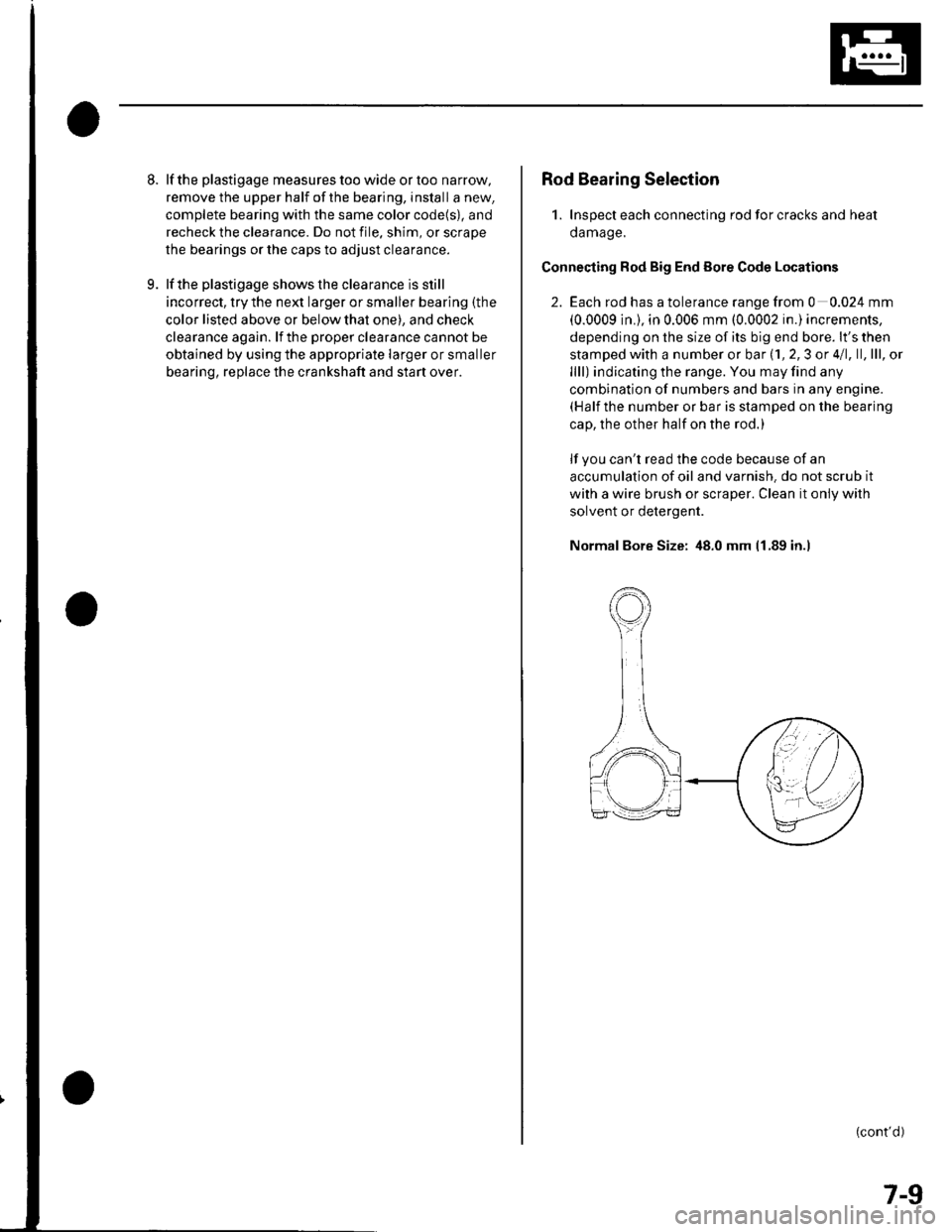
Connecting Rod Big End Eore Code Locations
2. Each rod has a tolerance range from 0 0.024 mm
(0.0009 in.), in 0.006 mm (0.0002 in.) increments,
depending on the size of its big end bore. lt's then
stamped with a number or bar (1, 2,3 or 4/1, ll,lll, ol
llll) indicating the range. You may find any
combination of numbers and bars in any engine.(Half the number or bar is stamped on the bearing
cap, the other half on the rod.)
lf you can't read the code because of an
accumulation of oil and varnish. do not scrub it
with a wire brush or scraper. Clean it only with
solvent or detergent.
Normal Bore Size: 48.0 mm 11.89 in.l
(cont'd)
7-9
Page 154 of 1139
Engine Block
Block and Piston Inspection (cont'd)
Scored or scratched cylinder bores must be honed.
Check the top of the block for warpage. Measure
along the edges and across the center as shown.
Engine Block Warpage
Standard lNew): 0.07 mm (0.003 in.) max.
Service Limit: 0.10 mm (0.004 in.l
PRECISION STRAIGHT EDGE
7-16
\
7. Calculate the difference between the cylinder bore
diameter and the plston diameter. lf the clearance
is near or exceeds the service limit, inspect thepiston and cvlinder block for excessive wear.
Piston-to-Cylinder Clearance
Standard lNew): 0.020 0.040 mm
{0.0008 0.0016 in.)
Service Limit: 0.05 mm (0.002 in.l
++ PISTON-TO-CYLINDERCLEARANCE
\
(
Page 159 of 1139
Piston Ring Replacement
1. Remove the piston {rom the cylinder block (see
page 7 -121.
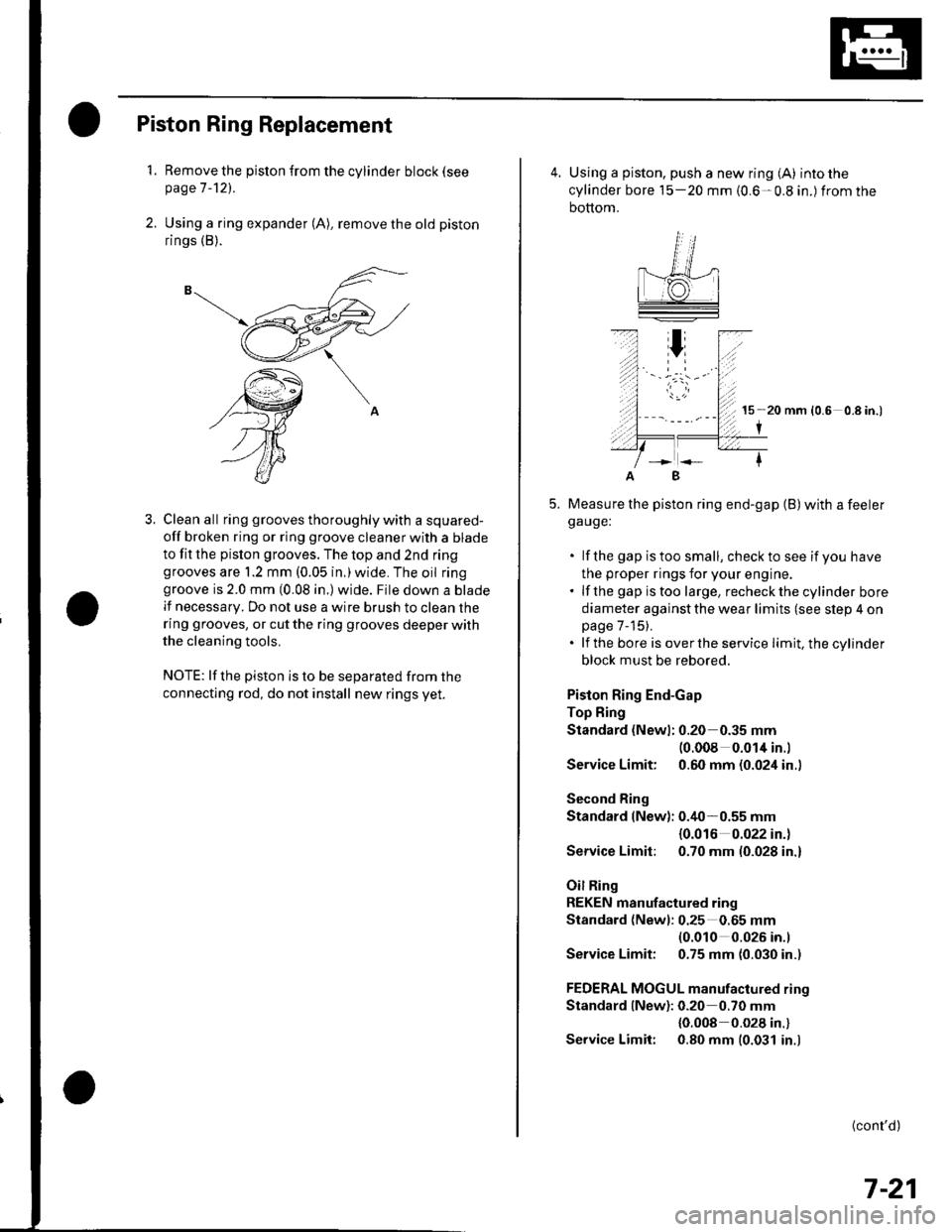
2. Using a ring expander (A), remove the old piston
rings (B).
3. Clean all ring grooves thoroughly with a squared-
off broken ring or ring groove cleaner with a blade
to fit the pislon grooves. The top and 2nd ringgrooves are 1.2 mm (0.05 in,)wide. The oil ringgroove is 2.0 mm (0.08 in.) wide. File down a blade
lf necessary. Do not use a wire brush to clean the
ring grooves, or cut the ring grooves deeper with
the cleaning tools.
NOTE: lf the piston is to be separated from the
connecting rod, do not install new rings yet.
4. Using a piston, push a new ring (A) into the
cylinder bore 15-20 mm {0.6-0.8 in.) from the
bottom.
15 20 mm (0.6 0.8 in.)
I
Measure the piston ring end-gap (B) with a feelerga uge:
. lf the gap istoo small, checkto see if you have
the proper rings for your engine.. lf the gap istoo large, recheckthecylinder bore
diameter against the wear limits (see slep 4 onpage 7-15).. lf the bore is overthe service limit, the cylinder
block must be rebored.
Piston Ring End-Gap
Top Fing
Standard (Newl: 0.20 0.35 mm(0.008 0.014 in.l
Service Limit: 0.60 mm (0.024 in..
Second Ring
Standard (New): 0.40-0.55 mm
{0.016 0.022 in.)
Service Limit: 0.70 mm (0.028 in.)
Oil Ring
REKEN manufactured ring
Standard (Newl: 0.25 0.65 mm(0.010 0.026 in.l
Service Limit: 0.75 mm (0.030 in.)
FEDERAL MOGUL manufactured rino
Standard lNew): 0.20 0.70 mm
{0.008 0.028 in.}
Service Limit: 0.80 mm (0.031 in.)
B
(cont'd)
7-21
Page 161 of 1139
Piston Installation
lf the crankshaft is already installed
1. Setthe crankshaftto bottom dead center (BDC) for
each cylinder.
2. Remove the connecting rod caps, then install the
ring compressor, and check that the bearing is
securely in place,
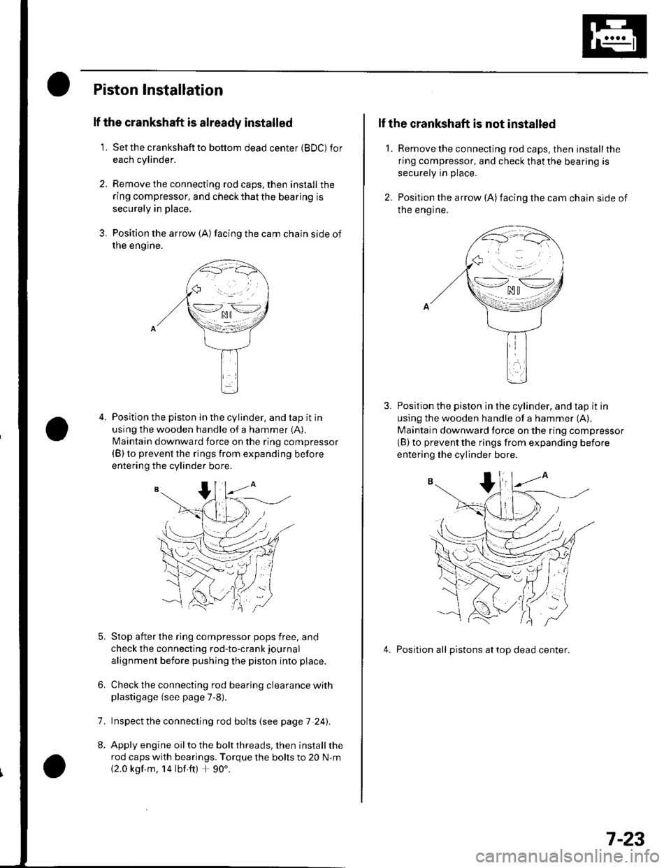
3. Position the arrow {A) facing the cam chain side of
rne engtne.
Position the piston in the cylinder, and tap it in
using the wooden handle of a hammer (A).
N4aintain downward force on the ring compressor(B) to prevent the rings from expanding before
entering the cylinder bore.
Stop after the ring compressor pops free, and
check the connecting rod-to-crank journal
alignment before pushing the piston into place.
Check the connecting rod bearing clearance withplastigage (see page 7-8).
lnspect the connecting rod bolts (see page 7 241.
Apply engine oil to the bolt threads, then install the
rod caps with bearings. Torque the bolts to 20 N.m
{2.0 kgf m, 14 lbf ft) + 90'.
6.
7.
2.
1.
lf the crankshaft is not installed
Remove the connecting rod caps. then install the
ring compressor, and check that the bearing is
securely in place.
Position the arrow (A)facing the cam chain side of
Ine engrne.
Position the piston in the cylinder, and tap it in
using the wooden handle of a hammer (A),
Maintain downward force on the ring compressor(B) to prevent the rings from expanding before
entering the cylinder bore.
4. Position all pistons attop dead center.
\--lno n\-.--l. ^u t
>-*/zi
.,.'_\pf{
wr
(( 'V,/ :
7-23
Page 162 of 1139
Engine Block
Connecting Rod Bolt Inspection
Measure the diameter of each connectinq rod bolt
at Doint A and ooint B.
35 mm
Calculate the difference in diameter between point
A and point B.
Point A-Point B = Difference in Diameter
Diflerence in Diameter:
Specification: 0 0.1 mm (0 0.004 in.)
lf the difference in diameter is out of tolerance,
replace the connecting rod bolt.
1.
3,
mm
7-24
\-
Crankshaft Installation
Special Tools Bequired. Driver 07749-0010000. Attachment, 24 x 26 mm 07746-0010700. Oil seal driver attachment 96 o7ZAD-PNAAl00
1. Install the crankshaft end bushing with the special
tools when replacing the crankshaft. Drive in the
crankshaft end bushing until the special tools
bottom aqainst the crankshaft.
07749-0010000
07746-00'l
Check the connecting rod bearing clearance with
plastigage {see page 7-8).
Check the main bearing clearance with plastigage
(see page 7-6).
lnspectthe connecting rod bolts (see pageT-241.
(
I\-(
4.
a
Page 170 of 1139
Engine Lubrication
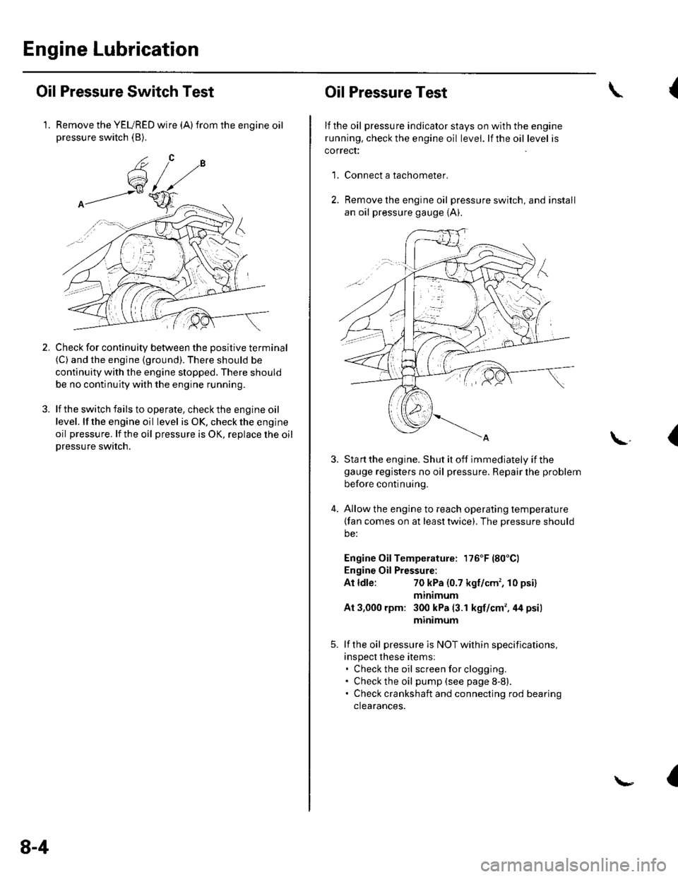
Oil Pressure Switch Test
1. Remove the YEURED wire (A)from the engine oilpressure switch (B).
Check for continuity between the positive terminal(C) and the engine (ground). There should be
continuity with the engine stopped. There should
be no continuity with the engine running.
lf the switch fails to operate, check the engine oil
level. lf the engine oil level is OK. check the engine
oil pressure. lf the oil pressure is OK, replace lhe oil
Dressure switch.
2.
8-4
Oil Pressure Test
lf the oil pressure indicator stays on with the engine
running. check the engine oil level. lf the oil level is
correct:
Connect a tachometer.
Remove the engine oil pressure switch, and install
an oil pressure gauge {A).
{
'1.
\.(
4.
Sta rt the engine. Shut it off immediately if thegauge registers no oil pressure. Repair lhe problem
before continuing.
Allow the engine to reach operating temperature(fan comes on at least twice), The pressure should
be:
Engine Oil Temperature: 176'F (80'Cl
Engine Oil Pressure:
At ldle:70 kPa (0.7 kgf/cm', 10 psi)
mtntmum
At 3,000 rpm: 300 kPa (3.1 kgf/cm',44 psi)
minimum
lf the oil pressure is NOT within specifications,
inspect these items:. Check the oil screenforclogging.. Check the oil pump (see page 8-8).. Check crankshaft and connecting rod bearing
clearances.
I