Page 497 of 1139
I
Steering Linkage and Gearbox Inspection
Check for looseness,and binding.
TIE.ROD LOCKNUTSCheck for looseness.
BOOTInspect Ior damage and deterioration.
12 mm BOLTSInspect for looseness.
STEERING COLUMNInspect for loose columnmounting hardware
STEERING GEARBOXInspect for loose mounting hardware.GEARBOX MOUNTING CUSHIONSInspect for deterioration.
STEERING JOINTSCheck for loose ioint bolts,and loose or binding ioints.
TIE.ROD ENO BALL JOINTlnsoect tor looseness,binding, and damage.
BALLJOINT BOOTInspect for damage and deterioration.
17-5
Page 506 of 1139
Electrical Power Steering (EPSI
SpecialTools ............. 17 -16
Component Location Index ......................................... 17-17
General Troubleshooting Information ....................... 17-18
DTC Troubleshooting Index .............. 17-22
Symptom Troubleshooting Index ............................... 17 -23
System Description ................. ........... 17-24
Circuit Diagram ......... 17-26
DTC Troubleshooting ............... .......... 17-28
EPS lndicator Circuit Troubleshooting ....................... 17-47
Motor Removal/lnstallation ............... 17-49
Steering Gearbox Removal ............... 17-51
Steering Gearbox Overhaul ............... 17-55
Steering Gearbox Installation ........... 17-63
EPS Control Unit Remova l/lnsta llation ....................... 17-67
Tie-rod Ball Joint Boot Replacement .......................... 17-67
Page 546 of 1139
I x '1.25 mm20 N.m (2.0 kgf.m,7.2lbt ftl
O.RINGReplace.
PINION SHAFT GROMMET
-'t ''
v
\>--. i-*\{i#r^i
. s(./t' J
SLTDER GUIDE
-l
\
{^il stot *,tttc
\J" Renrace
LocK scREw '162 N.m lto.s rgf m,119lbf ft)
BOOTBAND Beqtace.
- Replace.
@
II
ASHER
rtE54
TIE.ROD END
CONNECTOR
Steering Gearbox Overhaul
Exploded View
RACK GUIDE
6^:,;�
BOOT BAND '"''/
Beplace.
. -@ -sPRrNG. DISC WASHEB @'---g
L)-RACKGUIDE SCREW
6v---\' \.oc**u.
SRACKET
LOCK WReplace.
-RODN m {5.5 kgf.m,40lbf ft)
kgf.m,
(cont'd)
17-55
33 tbt.ft)44 N m {4.5
Page 548 of 1139
6. Remove the two boot bands (A) from boot (B).
Compress the boot by hand, and apply vinyl tape
(C) so the boot ends stay collapsed and pulled back
Attach the yoke (A) of a universal puller to the
steering gearbox mounts with bolts. Securely
clamp the yoke in a vise as shown. Do not clamp
the steering gearbox housing in the vise.
1.
10.
8. Installthe special tool (A) on the lock screw (B)
securely. then loosen and remove the lock screw
from the steering gearbox housing.
07zAA-S5A0r00
Remove the special tool.
Pull on the rack housing (A) to remove it from the
steering gearbox housing, Remove the boot {B) and
slider guide (C) from the cylinder.
(cont'd)
17-57
Page 550 of 1139

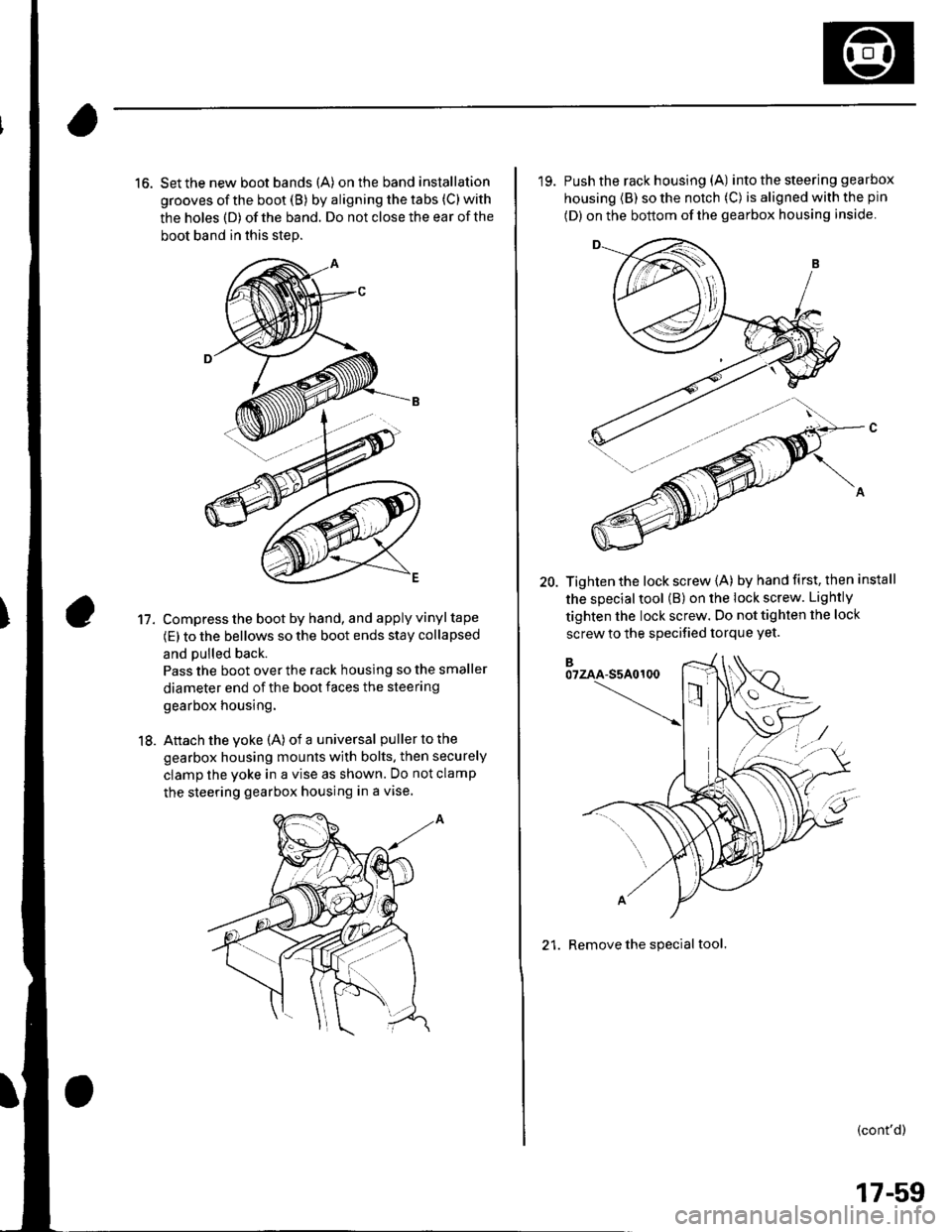
16. Set the new boot bands (A) on the band installation
grooves of the boot (B) by aligning the tabs (C) with
the holes (D) of the band. Do not close the ear of the
boot band in this step.
Compress the boot by hand, and apply vinyl tape
(E) to the bellows so the boot ends stay collapsed
and pulled back.
Pass the boot over the rack housing so the smaller
diameter end of the boot faces the steering
gearbox housing.
Attach the yoke (A) of a universal puller to the
gearbox housing mounts with bolts. then securely
clamp the yoke in a vise as shown. Do not clamp
the steering gearbox housing in a vise.
11.
18.
'19. Push the rack housing (A) into the steering gea rbox
housing (B) so the notch (C) is aligned with the pin
(D) on the bottom of the gearbox housing inside
20. Tighten the lock screw {A) by hand first, then install
the special tool (B) on the lock screw. Lightly
tighten the lock screw. Do not tighten the lock
screw to the specified torque Yet.
21. Remove the special tool.
(cont'd)
17-59
Page 551 of 1139

EPS Components
{Steering Gearbox Overhaul (cont'dl
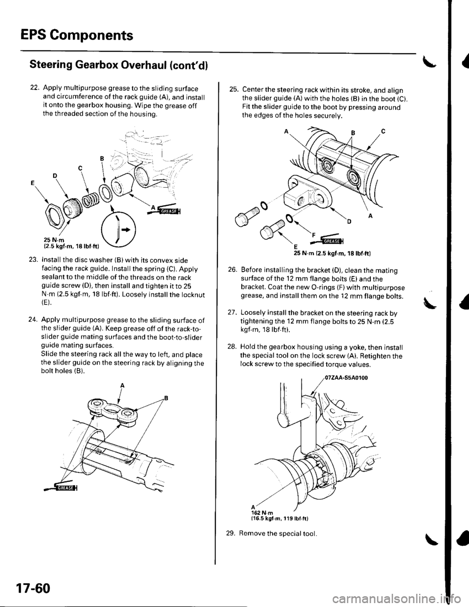
22. Apply multipurpose grease to the sliding surfaceand circumference ofthe rackguide (A), and installit onto the gearbox housing. Wipe the grease offthe threaded section ofthe housrno.
...'.
,. ,l
.j
23. Installthe disc washer (B)with its convex sidefacing the rack guide. Installthe spring (C). Appty
sealant to the middle of the threads on the rackguide screw (D), then install and tighten it to 25
N m (2.5 kgf.m, 18 lbf.ft). Loosely instatlrhe tocknut(E).
24. Apply multipurpose grease to the sliding surface ofthe slider guide (A). Keep grease off of the rack-to-slider guide mating surfaces and the boot-to-sliderguide mating surfaces.
Slide the steering rack all the way to left, and place
the slider guide on the steering rack by aligning thebolt holes (B).
'1 - .- =-1, -
17-60
29.
25. Centerthe steering rack within its stroke, and alignthe slider guide (A)with the hotes (B) in the boot (C).
Fit the slider guide to the boot by pressing around
the edges of the holes securely
E25 N.m 12.5 kgt.m, 18 tbt.ft)
26. Before installing the bracket (D), clean the mating
surface ofthe 12 mm flange bolts (E) and thebracket. Coat the new O-rings {F) with multipurposegrease, and installthem on the '12 mm flange bolts.
27. Loosely install the bracket on the steering rack bytightening the 12 mm flange bolts to 25 N.m (2.5
kgf.m, 18lbf.ft).
28. Hold the gearbox housing using a yoke, then install
the specialtool on the lock screw (A). Retighten thelock screw to the specified torque values.
{16.5 kgt.m, 119 lbf.ft}
Remove the special tool.
A
Page 552 of 1139
30, Retighten the 12 mm flange bolts (A) to the
soecified toroue value.
After tightening the 12 mm flange bolts, install a
new stop plate (B) over one of the bolt heads. Be
sure the tabs (C) of the stop plate are aligned with
the flat surfaces of the bolt head.
Clean off any grease or contamination from the
boot installation grooves on the housing.
Expand the boot (A) by removing the vinyltape,
and fit the boot ends (B) in the installation grooves
on the cylinder housing.
5t.
32,
74 N.m (7.5 kgf.m,5ir lbf.ft)
34. Close the ear portion (A) ofthe bands (B)with
commerciallv available pincers, Oetiker 1098 or
equivalent (C).
35. Installthe new lock washer (A) with its radiused
side facing (B) the tie-rod (C), and screw the tie-rod
on the bracket (D). Repeat this step for the other
side of the tie-rod. Hold the bracket with one
wrench, and tighten the tie-rods to the specified
torque with another wrench.
,,";=-...,.,
(cont'd)
*=,,',
17-61
Page 558 of 1139

EPS Control Unit Removal/
Installation
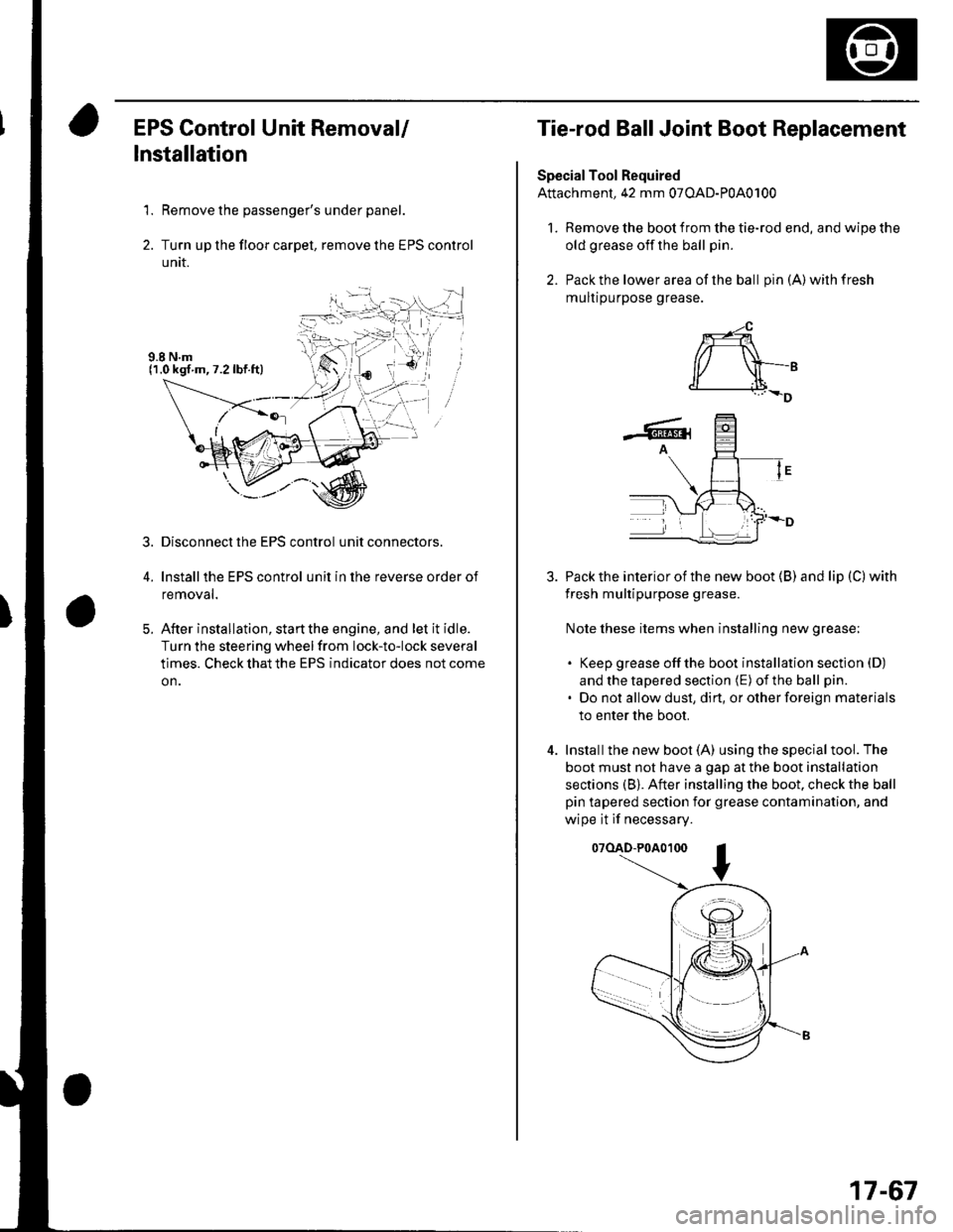
1. Remove the passenger's under panel.
2. Turn up the floor carpel, remove lhe EPS control
untr.
Disconnect the EPS control unit connectors.
lnstallthe EPS control unit in the reverse order of
removal.
After installation, start the engine, and let it idle.
Turn the steering wheelfrom lock-to-lock several
times. Check that the EPS indicator does not come
on.
3.
E
Tie-rod Ball Joint Boot Replacement
Special Tool Required
Attachment, 42 mm 07OAD-P0A0100
l. Remove the boot from the tie-rod end, and wipe the
old grease off the ball pin.
2. Pack the lower area of the ball pin(A)wilhfresh
mulr purpose grease.
3. Pack the interior of the new boot (B) and lip (C) with
fresh multipurpose grease.
Note these items when installing new grease;
. Keep grease offthe boot installation section (D)
and the tapered section (E) of the ball pin.
. Do not allow dust, dirt, or other foreign materials
to enter the boot.
4. Installthe new boot (A) using the specialtool. The
boot must not have a gap at the boot installation
sections (B). After installing the boot. check the ball
pin tapered section for grease contamination, and
wipe it if necessary.
07(lAD-P0A0100
*-4
r/ \-,d______i.l+_D
-6rA
17-67