2002 HONDA CIVIC horn
[x] Cancel search: hornPage 983 of 1139

Keyless/Power Door Lock System
UNDEN HOOD FU8E/BELAY MX
l\b r t15a) FUSE
Circuit Diagram (cont'dl\J
t"-HORNSWTCH
UNDEN DAS}I FUSE/8ELAY 8OX
tJ
Y,,,
Df,IVEB'S0008swtrcHplo'.d l
DFIVES'SDOOBTOCK6WTCH
tG tltot IGYstvrTcH
mMErNAlloflLIGHI SWITCH
HATCHLATCHswlrol
22-152
\
Page 987 of 1139

Keyless/Power Door Lock System
Control Unit Input Test (cont'dl
5. Reconnect all connections to the underdash fuse/relay box, and make these input tests at the appropriate connectors on the under-dashfuse/relay box.
'lfanytestindicatesaproblem,findandcorrectthecause,thenrecheckthesystem.. lf all the inputtests prove OK, goto step 6.
CavitvWireTest conditionTest: Desired resultPossible ca use if result is notobtainedc1'l8LUUnder all conditionsAftach to ground:Parking, side marker, licenseplate lights, and tajllights shouldcome on.
Blown No.2 (15A)fuse in the underhood fuse/relay boxFaulty taillight relayFaulty under-dash fuse/relay boxAn onen in rhc wireBLU/BEOUnder all conditionsAttach to ground:Headlights should come on.Blown No. 15 or 17 (15A)fuse in theunderhood fuse/relay boxFaulty headlight relay '1 or 2An ooen in the wireJ2WHT/REDUnder all conditionsCheck for voltage to ground:There should be battery voltage.Blown No.9 (15A)fuse in the under-hood fuse/relay boxAn oncn in thc wircBLKUnder all conditaonsCheck for voltage to ground:Thcre shouln hc 1 V or lpqsPoor ground (G501)An ooen in the wireJ6OBNUnder allconditionsAttach to ground:The horns should sound.Blown No. 7 (15A)fuse in the underhood fuse/relay boxFaulty horn relayFaulty hornsAn 6nen in rhe wireJ7Under all conditionsCheck for voltage to ground:There should be battery voltage.Elown No. 16 (20A)fuse in the underhood fuse/relay boxAn oocn in ihc wi.cP18BEDHatch openCheck for voltage to ground:There should be 1 V or less.Poor ground (G552)Faulty hatch latch switchAn oncn in rhc wirFHatch closedCheck for voltage to groundlThere shoul.l he 5 V or moreFaulty hatch latch switch
GBNDriver's door openCheck for voltage to g.ound:There should be 1 V or less. Faulty driver's door switch. An ooen in the wireDriver's door closedCheck for voltage to ground:There should be 5 V or more.Faulty driver's door switchShort to oroundo4LT GRN/REDPassenger's door openCheck for voltage to ground:There should be 1 V or less.Faulty passenger's door switchAn ooen inthewirePassenger's door closedCheck for voltage to groundlThere should be sVor more
. Faulty passenger's door switch. Short to oroundX5REDAVHTlgnition key inserted intothe ignition swhchCheck for voltage to ground:There should be 1 V or less.Poor ground {G401)Faulty ignition key switchAn ooen inthewirelgnition key removed fromrhe ionition switchCheck for voltage to ground:There should be 5 V or more.Faulty ignition key switchShort to oroundY1WHT/BLKDriver's door lock knobswitch unlockedCheck for voltage to groundlThere should be 1 V or less.Poorground (G50'l)Faulty driver's door lock knob switchAn open in the wireDriver's door lock knobCheck for voltage to groundlIhere should be 5 V or more.Faulty driver's door lock knob switchShort to oroundY8YEUREDDriver's door lock knobswitch lockedCheck for voltage to groundlThere should be 1 V or less.Poorground (G50'l)Faulty driver's door lock knob switchAn oncn inihewireDriver's door lock knobswitch unlockedCheck for voltage to ground:There should be 5Vor more' Faulty driver's door lock knob sw;tch. Shorr to oroundY10WHT/GRNDrtver's door lock switchunlockedCheck for voltage to groundlThere should be 1 V or less.Poorground (G501iFaulty driver's door lock switchAn ooen in the wireDriver's door lock switch inCheck for voltage to ground:Therc shorl.l be 5V or m6rpFaulty driver's door lock switchShort to o rolrndY12WHT/BLUDriver's door lock switchlockedCheck for voltage to ground:There should be 'l V or less.Poor ground (G501)Faulty driver's door lock switchAn oDen in the wireDriver's door lock switch inCheck tor voltage to ground:There should be 5Vor moreFaulty driver's door lock switch
22-156
J
Page 1021 of 1139

sRs
Precautions and Procedures
General Precautions
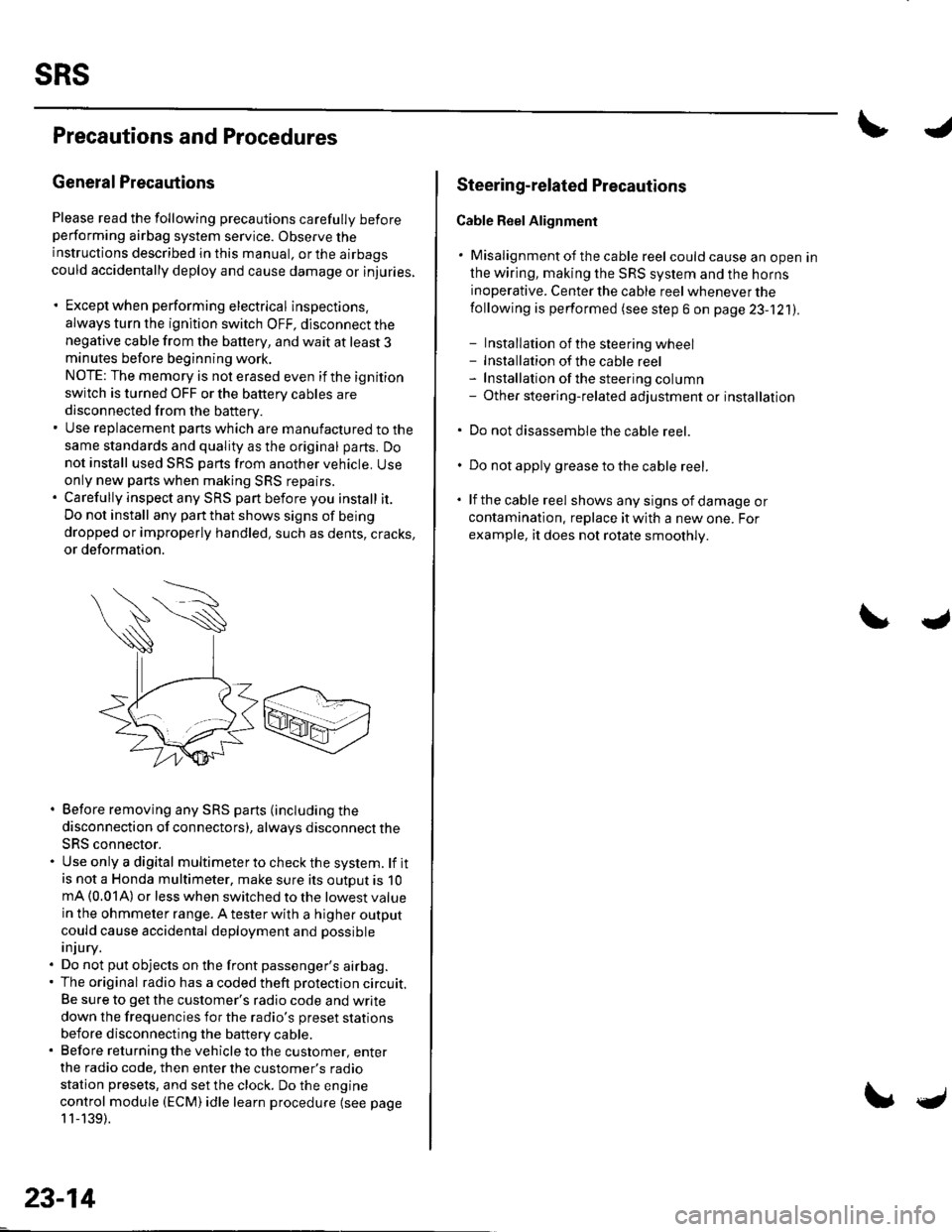
Please read the following precautions carefully beforeperforming airbag system service. Observe theinstructions described in this manual. or the airbags
could accidentally deploy and cause damage or injuries.
. Except when performing electrical inspections.
always turn the ignition switch OFF, disconnect the
negative cable from the battery, and wait at least 3minutes before beginning work.
NOTE: The memory is not erased even if the ignition
switch is turned OFF or the battery cables are
disconnected from the battery.. Use replacement pans which are manufactured to the
same standards and quality as the original parts. Do
not install used SRS parts from another vehicle. Useonly new pans when making SRS repairs.. Carefully inspect any SRS part before you install it.
Do not install any part that shows signs of being
dropped or improperly handled, such as dents, cracks,
or deformation.
. Before removing any SRS parts (including the
disconnection of connectors), always disconnect the
SRS connector.. Use only a digital multimeter to check the system. lf itis not a Honda multimeter, make sure its outout is 10mA (0.01A) or less when switched to the lowest value
in the ohmmeter range. A tester with a higher output
could cause accidental deployment and possible
injury.. Do not put objects on the front passenger's airbag.. The original radio has a coded theft protection circuit.
Be sure to get the customer's radio code and write
down the frequencies for the radio's preset stations
before disconnecting the battery cable.. Before returning the vehicle to the customer, enter
the radio code. then enter the customer's radio
station presets, and set the clock. Do the engine
control module (ECM) idle learn procedure (see page
11-139).
23-14
c
Steering-related Plecautions
Cable Reel Alignment
. Misalignment of the cable reel could cause an open in
the wiring, making the SRS system and the horns
inoperative. Center the cable reel whenever the
following is performed (see step 6 on page 23-121).
- Installation of the steering wheel- Installation of the cable reel- Installation ofthe steering column- Other steering-related adjustment or installation
. Do not disassemble the cable reel.
. Do not apply grease to the cable reel.
. lf the cable reel shows any signs of damage or
contamination. replace it with a new one. For
example, it does not rotate smoothly.
Page 1120 of 1139

A
\'l9
Driver's Airbag Replacement
Removal
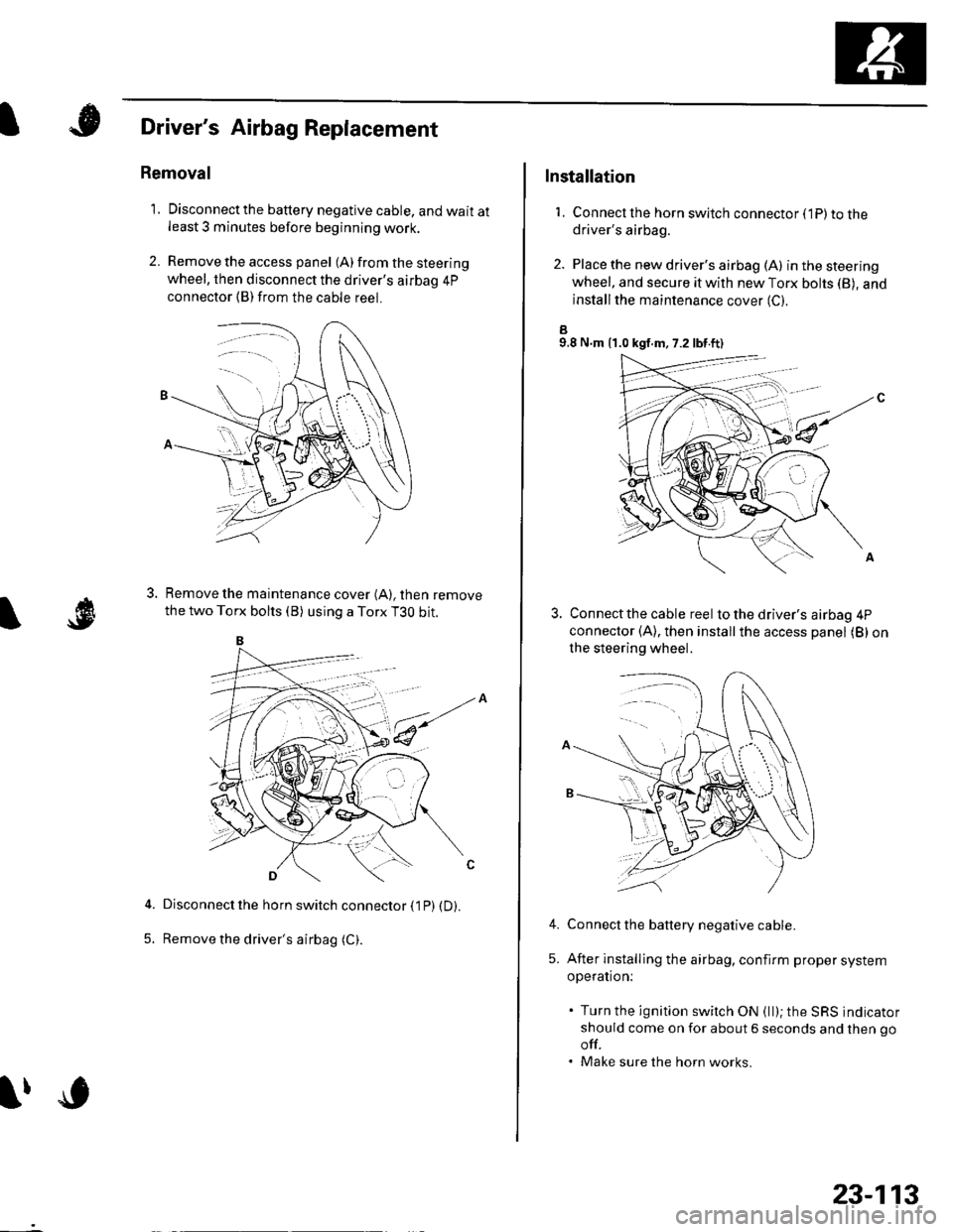
1. Disconnectthe battery negative cable, and wait atleast 3 minutes before beginning work.
2. Remove the access panel (A) from the steering
wheel, then disconnect the driver's airbag 4p
connector (B)from the cable reel.
Remove the maintenance cover (A), then remove
the two Torx bolts (B) using a Torx T3O bit.
Disconnect the horn switch connector (1P) (D).
Remove the driver's airbag (C).5.
lfc
23-113
Installation
1. Connect lhe horn switch connector (1P) to thedriver's airbag.
2. Place the new driver's airbag (A) inthesteering
wheel, and secure it with new Torx bohs (B), and
installthe maintenance cover (C).
a9.8 N.m {1.0 kgf.m, 7.2 lbt.ft)
Connect the cable reel to the driver's airbag 4P
connector (A), then installthe access panel (B) on
the steering wheel.
Connect the battery negative cable.
After installing the airbag, confirm proper system
operation:
. Turn the ignition switch ON (ll); the SRS indicator
should come on for about 6 seconds and then go
off.. Make sure the horn works.
4.
5.
Page 1128 of 1139

)
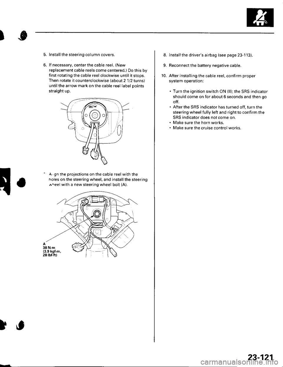
Install the steering column covers.
lf necessary, center the cable reel. {New
replacement cable reels come centered.) Do this by
first rotating the cable reel clockwise until it stops,
Then rotate it counterclockwise labout 2 1 12 lurns)
untilthe arrow mark on the cable reel label Doints
straight up.
- A gn the projections on the cable reel with the
noles on the steering wheel, and installthe steering
Ai\eel with a new steering wheel bolt (A).
)c
23-121
8. lnstallthe driver's airbag (see page 23-113).
9. Reconnect the battery negative cable.
10. After installing the cable reel, confirm proper
syslem operalton:
. Turn the ignition switch ON (ll); the SRS indicator
should come on for about 6 seconds and then go
off.. After the SRS indicator has turned off, turn the
steering wheel fully left and right to confirm the
SRS indicator does not come on.. Make sure the horn works.. Make sure the cruise control works,
Page 1136 of 1139

Service Manual Index
(cont'dl
Gauge A3semblyReplacement......................................... 22 64
Gaug€sComponent Location Index ..........-...... 22 54How-to lnformation ........................22-56Circuit Diagram22-54
Heater Valve CableAdjustment ...................... .................... ?1-46
High Mount Brake Light8ep|acement......................................... 22 82
Hood
lmmobilizer SystemComponent Location In dex .............. 22-162
\
G
Description
Genoral Information(See seclion 1)
Glove BoxRemoval/1nsta11ation .......................-.... 20-63
GrilleReplacement...........-............................. 20-94
Hood lnsulatorReplacement......................................... 20-89
Hood LatchRep1acement................... ..........20 108
Hood Opener CableComponentLocation Index ..............20 105Replacement ................ . . ........... .....20 106
Hood SealBeplacement.-...........................-........... 20-88
HornTesVReplacement . . ................ ...... 22-122
CircuitDiagram ...........................22-164Troubleshooting ............................ 22,165
Inner Fender, FronlRepf acemenl....................................... 20-102
Inside Rearview MirrorReplacement..........-.............................. 20 16
Instrument PanelRemoval/1nsta11ation................. ....... 20-59
Intake Air Bypass ControlThermal ValveTesr................................ ..... ..11-161
Intake Air SystemComponent Location Index ...-.-........ 11-159
Intake ManitoldRemoval/1nsta11ation ................................ I 2
lntermediate Shaft AssemblyRemova1 ................-.-...-......................... 16-19Disassemb|y................... ... ......-.... 16,20Resassemb|y ........................................ 16 22Installation .........-...-.............................. 16-24
Keyless Entry Transmitter
Adjuslment
H
Adiustment .......
Hatch Handle
Horn SwitchTest ............-........
HornsComponent Location IndexCirc!it Diagram
H02S. SecondaryReplacement
..............22-120Replacement
22-122
22 12120-110
20-'110Hatch LatchReplacement$
K
Hatch Latch Switch
.... 11 113
HubsReplacement. ... .................................. 1A 26Test
Test
Replacement
Hatch Support StrutsBeplacement.....
Hatch WeatherstrioReplacement....
Hazard Warning Switchtest
ldle ControlSystemComponentLocation Index .............. 11-129Inspection,.,.........-.......,.,.,,,,,,.,,,.,.,..... 1'l 138
lgnition CoillslBemoval/lnstallation ...............-.............. 4 18
22-161Test ...................................................... 22 161
Keyless Entry/Security Alarm SystemComponenl Location Index .............. 22 150Circuil Diagram ................. . .............. 22 151
Keyless Receiver Unitlnput Test ............................................ 22-153
Knock SensorReplacement......-................................ 1 1 115
KnucklesReplacementFront Suspensron ............................. 18-1 1Rear Suspension ........ .................-... 18-28
Repair ...............
H.tch Lock Actuator22-159
Hatch Lock CylinderRep|acement....................................... 20,111
Hatch SpoilerIAT {lntake Air Temperature} SensorReplacement.,.........-...'11 115
20-91
20-92
.................... 22_88lgnition Key LightTest,,.,,,,.,...,......-.
H6adlightAdjustmentlgnition Key Switch
....................... 22-91
....................... 22-91..22-78TestReQ\ace$entlgnition SwitchTest .,,,.,.,.,,,,.,.,.......22-53License Plate LightReplacement...........-... - ... .....22-83
License TrimReplacement..................-...-..........-....... 20-98
Lights, ExteriorComponent Localion Index.................22 68
Lights,InteriorComponent Location Index................. 22-94CircuitDiagram .. .. ...... .... 22-95
HcadlightsCircuit Diagram .............................. 22-71, 72
HeadlinerRemoval/lnstallalion ............................ 20-54
Heater ControlPanelRemoval/1nsta11ation ............................ 21-38
Heater Control Power and Ground CircuitsTroubfeshooting......... .......................21-27
lgnition SystemComponent Location Index ................... 4-15CircuitDia9ram .................................... 4'161nspection ............................................... 4-17
lmmobilizer Control Unit-Receiver
J
22-161