2002 HONDA CIVIC glove box
[x] Cancel search: glove boxPage 863 of 1139

Connectors and Harnesses
Connector to Harness Index (cont'd)
ECM Wire Harness
Connector or TerminiFI Re-lcavitiesL LocationConnectstoNotesArr ruer t/vrl ralo sensor retayData link connectorEC[/l connector EPGM-Fl main relay 1PGM-Fl main relay 2Under-dash fuse/relay boxconnector D (see page 22 45)Underdash fuse/relay boxconnector E lsee page 22-45)under-dash fuse/relay boxconnector R lsee page 22-45)c10'1
c152
c451
c452
c453
c511
8761
2
3
4
1'�I
I
10
14
12
44
6
20
8
4
6
Eehind glove boxUnder middle of dashBehind glove boxBehind glove boxBehind glove boxIn the under-dash fuse/relay box
In the under-dash fuse/relay box
In the under-dash fuse/relay box
Under rlght side of dash
Under right side of dash
Under right side of dash
Under right side ot dash
Under middle oI dash
Under middle of dash
Engine wire harness (seepage 22'16)EPS sub harness (see page22-24)Engine companment wireharness {see page 22-18)Engine compartment wireharness {see page 22-18)Floor wire harness (see page22-34)Dashboard wire harness A{see oaoe 22-26)G451Under gauge assemblyBody ground via ECM wireharness
22-32
Page 1121 of 1139

sRs
Front Passenger's Airbag Replacement
Removal
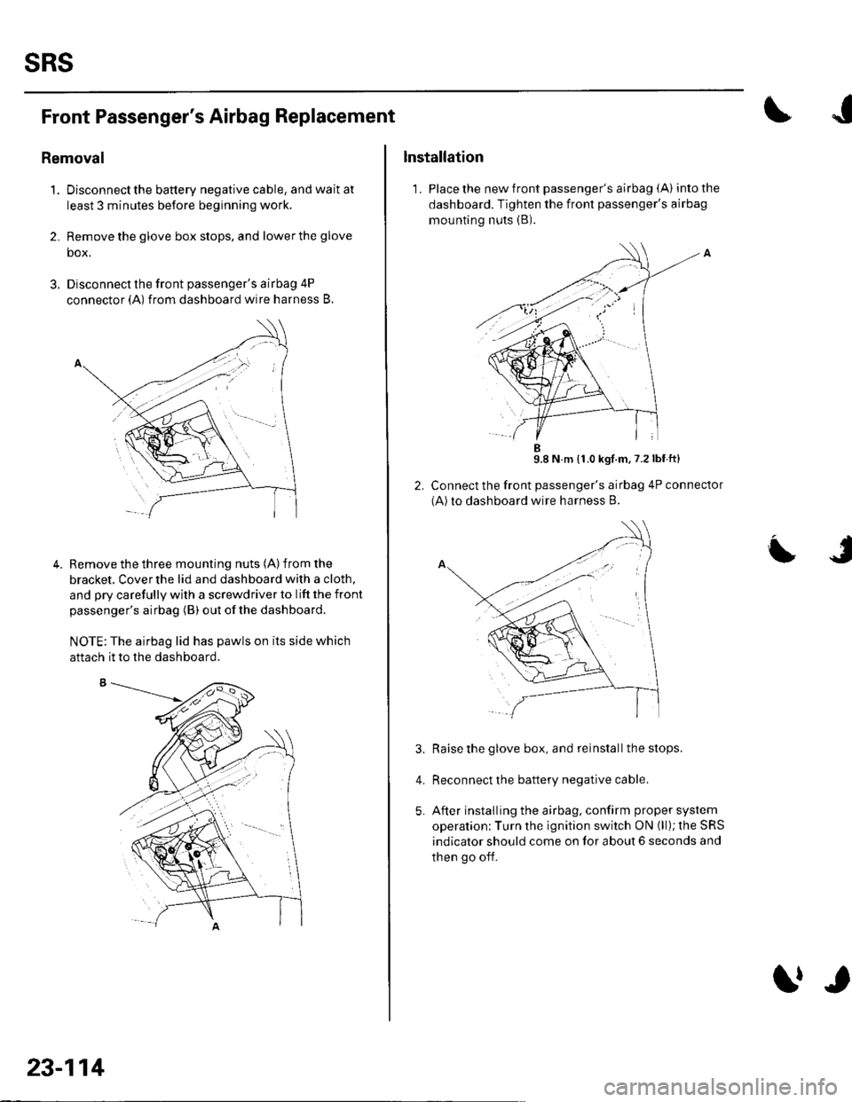
1. Disconnectthe battery negative cable, and wait at
least 3 minutes before beginning work,
2. Remove the glove box stops, and lower the glove
box.
3. Disconnect the front passenger's airbag 4P
connector (A) from dashboard wire harness B.
Remove the three mounting nuts (A) from the
bracket. Cover the lid and dashboard with a cloth,
and pry carefully with a screwdriver to lift the front
passenger's airbag (B) out ofthe dashboard.
NOTE:The airbag lid has pawls on its side which
4.
aftach it to the dashboard.
23-114
trr
Installation
1. Place the new front passenger's airbag (A) into the
dashboard. Tighten the front passenger's airbag
mounting nuts (B).
9.8 N m {1.0 kgf.m,7.2lbf ft}
Connect the front passenger's airbag 4P connector
(A)to dashboard wire harness B.
Raise the glove box, and reinstall the stops.
Reconnect the battery negative cable.
After installing the airbag, confirm proper system
operation; Turn the ignition switch ON (ll); the SRS
indicator should come on for about 6 seconds and
then go off.
L
4.
Page 1123 of 1139

sRs
Airbag Disposal
Special Tool Required
Deployment tool 07HAz-SG00500
Before scrapping any airbags, side airbags, seat belt
tensioners, or seat belt buckle tensioners (including
those in a whole vehicle to be scrapped), the airbags,
side airbags, seat belt tensioners, or seat belt buckle
tensioners must be deployed. lf the vehicle is still within
the warranty period, the Honda District Service
Manager must give approval and/or special instruction
before deploying the airbags, side airbags, seat belt
tensioners, or seat belt buckle tensioners. Only after the
airbags, side airbags, seat belt tensioners, or seat belt
buckle tensioners have been deployed (as the result of
vehicle collision, for example), can they be scrapped.
lf the airbags, side airbags, seat belt tensioners, and
seat belt buckle tensioners appear intact (not deployed),
treat them with extreme caution. Follow this Drocedure.
Deploying Airbags in the Vehicle
lf an SRS equipped vehicle is to be entirely scrapped, its
airbags, side airbags. seat belt tensioners. and seat belt
buckle tensioners should be deoloved while still in the
vehicle. The airbags, side airbags, seat belttensioners,
and seat belt buckle tensioners should not be
considered as salvageable parts and should never be
installed in another vehicle.
1. Turn the ignition switch OFF, then disconnect the
battery negative cable, and wait at least 3 minutes.
2. Confirm that each airbag, side airbag, or seat belt
tensioner is securely mounted.
3. Conf irm that the specia I tool isfunctioning properly
by following the check procedure on the tool label.
23-116
$J
Driver's Airbag:
4. Remove the access panel f rom the steering wheel,
then disconnect the driver's airbag 4P connector
from the cable reel (see step 2 on page 23-21).
Front Passenger's Airbag:
5. Lowerthe glove box, then disconnectthe front
passenger's airbag 4P connector from dashboard
wire harness B (see step 3 on page 23-211.
Side Airbag:
6. Disconnect the side airbag 2P connectors from the
floor wire harness (see step 4 on page 23-211.
Seat belt tensioner:
7. Disconnect the seat belt tensioner 2P connectors
from the floor wire harness {see step 5 on page 23-
22). Pull the seat belt out all the way, and cut it off.
Seat belt buckle tensioner:
8, Disconnect the seat belt buckle tensioner 4P
connectors from the floor wire harness (see step 6
on page 23-221.
Page 1136 of 1139

Service Manual Index
(cont'dl
Gauge A3semblyReplacement......................................... 22 64
Gaug€sComponent Location Index ..........-...... 22 54How-to lnformation ........................22-56Circuit Diagram22-54
Heater Valve CableAdjustment ...................... .................... ?1-46
High Mount Brake Light8ep|acement......................................... 22 82
Hood
lmmobilizer SystemComponent Location In dex .............. 22-162
\
G
Description
Genoral Information(See seclion 1)
Glove BoxRemoval/1nsta11ation .......................-.... 20-63
GrilleReplacement...........-............................. 20-94
Hood lnsulatorReplacement......................................... 20-89
Hood LatchRep1acement................... ..........20 108
Hood Opener CableComponentLocation Index ..............20 105Replacement ................ . . ........... .....20 106
Hood SealBeplacement.-...........................-........... 20-88
HornTesVReplacement . . ................ ...... 22-122
CircuitDiagram ...........................22-164Troubleshooting ............................ 22,165
Inner Fender, FronlRepf acemenl....................................... 20-102
Inside Rearview MirrorReplacement..........-.............................. 20 16
Instrument PanelRemoval/1nsta11ation................. ....... 20-59
Intake Air Bypass ControlThermal ValveTesr................................ ..... ..11-161
Intake Air SystemComponent Location Index ...-.-........ 11-159
Intake ManitoldRemoval/1nsta11ation ................................ I 2
lntermediate Shaft AssemblyRemova1 ................-.-...-......................... 16-19Disassemb|y................... ... ......-.... 16,20Resassemb|y ........................................ 16 22Installation .........-...-.............................. 16-24
Keyless Entry Transmitter
Adjuslment
H
Adiustment .......
Hatch Handle
Horn SwitchTest ............-........
HornsComponent Location IndexCirc!it Diagram
H02S. SecondaryReplacement
..............22-120Replacement
22-122
22 12120-110
20-'110Hatch LatchReplacement$
K
Hatch Latch Switch
.... 11 113
HubsReplacement. ... .................................. 1A 26Test
Test
Replacement
Hatch Support StrutsBeplacement.....
Hatch WeatherstrioReplacement....
Hazard Warning Switchtest
ldle ControlSystemComponentLocation Index .............. 11-129Inspection,.,.........-.......,.,.,,,,,,.,,,.,.,..... 1'l 138
lgnition CoillslBemoval/lnstallation ...............-.............. 4 18
22-161Test ...................................................... 22 161
Keyless Entry/Security Alarm SystemComponenl Location Index .............. 22 150Circuil Diagram ................. . .............. 22 151
Keyless Receiver Unitlnput Test ............................................ 22-153
Knock SensorReplacement......-................................ 1 1 115
KnucklesReplacementFront Suspensron ............................. 18-1 1Rear Suspension ........ .................-... 18-28
Repair ...............
H.tch Lock Actuator22-159
Hatch Lock CylinderRep|acement....................................... 20,111
Hatch SpoilerIAT {lntake Air Temperature} SensorReplacement.,.........-...'11 115
20-91
20-92
.................... 22_88lgnition Key LightTest,,.,,,,.,...,......-.
H6adlightAdjustmentlgnition Key Switch
....................... 22-91
....................... 22-91..22-78TestReQ\ace$entlgnition SwitchTest .,,,.,.,.,,,,.,.,.......22-53License Plate LightReplacement...........-... - ... .....22-83
License TrimReplacement..................-...-..........-....... 20-98
Lights, ExteriorComponent Localion Index.................22 68
Lights,InteriorComponent Location Index................. 22-94CircuitDiagram .. .. ...... .... 22-95
HcadlightsCircuit Diagram .............................. 22-71, 72
HeadlinerRemoval/lnstallalion ............................ 20-54
Heater ControlPanelRemoval/1nsta11ation ............................ 21-38
Heater Control Power and Ground CircuitsTroubfeshooting......... .......................21-27
lgnition SystemComponent Location Index ................... 4-15CircuitDia9ram .................................... 4'161nspection ............................................... 4-17
lmmobilizer Control Unit-Receiver
J
22-161