2002 HONDA CIVIC engine electrical
[x] Cancel search: engine electricalPage 342 of 1139

15. Check for continuity between body ground and
ECIM connector terminal 813.
ECM CONNECTOR B I24P}
Wire side of female terminals
ls there continuity?
YES Repair short in the wire between the ECM
(813) and the alternator.l
NO Update the ECM if it does not have the latest
software, or substitute a known-good ECM, then
recheck lsee page 1 1-6). lf the symptom/indication
goes away with a known-good ECM, replace the
original ECM.I
Electrical Power Steering (EPSI
Signal Circuit Troubleshooting
Turn the ignition switch ON (ll).
l\4easure voltage between ECM connector
terminals 424 and E16.
1.
2.
3.
4.
5.
Wire side of female terminals
ls there battery voltage?
YES Go to step 6.
NO Go to step 3.
Start the engine.
Turn the steering wheel lo the full lock position.
l\4easure voltage between ECM connector
terminals A24 and E16.
ls there momentaty battery voltage?
YES The EPS signal is OK.t
NO Go to step 10.
6. Turn the ignition switch OFF.
7. Disconnect the EPS control unit 20P connector.
8. Turn the ignition switch ON (ll).
(cont'd)
11-135
Page 346 of 1139

ECM ldle Learn Procedure
The idle learn procedure must be done so the ECM can
learn the engine idle characteristics.
Do the idle learn procedure whenever you do any of
these actions:. Disconnect the battery.
Replace the ECM or disconnect its connector.
Reset the ECM.
NOTE: Erasing DTCS with the Honda PGM Tester
does not require you to do the idle learn procedure.
Remove the No.6 ECU {ECM) ( 15A) fuse from the
under-hood fuse/relay box.
Remove the No.19 baftery (80A) fuse from the under-
hood fuse/relay box.
Remove PGM-FI main relay 1.
Remove any of the wires from the under-hood fuse/
retay Dox.
Disconnect any of the connectors from the under
hood fuse/relay box.
Disconnect the connector between the engine
compartment wire harness and ECM wire harness.
Disconnect the G2 terminal from the transmission
ho u srng.
Disconnectthe G'l terminal from the body.
Disconnectthe G101 terminal from the cylinder head
cover.
Procedure:
To complete the idle learn procedure, do this:
1. Make sure all electrical items (Ay'C, audio, rear
defogger, l:ghts, etc.,) are off.
2. Start the engine, and hold it at 3,000 rpm with no
load {in neutral) until the radiator fan comes on, or
until the engine coolanttemperature reaches 194"F(90'c).
3. Let the engine idle for about 5 minutes with the
throttle fully closed.
NOTE: lf the radiator fan comes on, do not include its
running time in the 5 minutes.
11-139
Page 625 of 1139

General Troubleshooting Information
ABS Indicator
. lf the system is OK,theABS indicator goes off 2
seconds after turning the ignition switch ON (ll)
without starting the engine, and then comes on again
and goes off 2 seconds later after starting the engine.
This occurs because the ABS control unitisturned
on by the lG2 power source.. The ABS indicator comes on when the ABS control
unit detects a problem in the system. However, even
though the system is operating properly, the indicator
will come on under these conditions:- Only the drive wheels rotate- One drive wheel is stuck- The vehicle goes into a spin- The ABS continues to operate for a long time.- The vehicle is subjected to an electrical signal
disturbance
To determine the actual cause of the problem, question
the customer about the problem. taking the above
condilions into consideration.
. When a Droblem is detected and lhe ABS indicator
comes on, there are cases when the indicator stays
on until the ignition switch is turned OFF, and cases
when the indicator goes off automatically when the
sYstem returns to normal.- DTC 61: The ABS indicator goes off automatically
when the system returns to normal.- DTC 11, 13,15,17 ,31,32,33, 34, 35, 36, 37, 38, 54,
or 81: The ABS indicator stays on until the ignition
switch is turned OFF whether or not the system
returns to normal.- DfC 12, 14, 16, 1a,21,51,52, or 53; The ABS
indicator goes off when the vehicle is driven again
and the system is OK after the ignition switch is
turned from OFF to ON {ll}.
Diagnostic Trouble Code {DTCI
. The memory can hold three DTCS. However, when
the same DTC is detected more than once, the more
recent DTC is written over the earlier one.
Therefore, when the same problem is detected
repeatedly, it is memorized as a single DTC.. The DTCs are in the order they occurred, beginning
with the most recent.. The DTCS are memorized in the EEPROM (non-
volatile memory). Therefore. the memorized DTCs
are not cleared when the battery is disconnected, the
ignition switch is turned off, or the system returns to
normal. Do the specified procedures to clear the
DTCs.
Self-diagnosis
. Self-diagnosis can be classified into two categories:- Initial diagnosis:
Done right after the engine starts and until the ABS
indicator goes off- Regular diagnosis:
Done rightafterthe initial diagnosis until the
ignition switch is turned OFF. When a problem is detected by self-diagnosis, the
system does the following:- Turns the ABS indicator on- Memorizes the DTC- Stops ABS control
Kickback
The pump motor operates when the ABS is functioning,
and the fluid in the reservoir is forced out to the master
cylinder, causing kickback at the brake pedal.
Pump Motor
. The pump motor operates when the ABS is
functioning.. The ABS control unit checks the pump motor
operation when the vehicle is started the first time
after the ignition switch is turned ON (ll). You may
hear the motor operate at this time, but it is normal.
(cont'd)
19-31
Page 814 of 1139

Heater Unit/Core Replacement
SRS components are located in this area. Review the
SRS component locations (see page 23'13), and
precautions and procedures (see page 23-14) in the SRS
section before performing repairs or service.
1. Make sure you have the anti-theft code forthe radio,
then write down the freouencies for the radio's
Dreset buttons.
4.
Disconnect the negative cable from the battery,
Disconnect the suction and receiver lines from the
evaporator core (see page 21-42).
From under the hood, open the cable clamp (A),
then disconnect the heater valve cable (B) from the
heater valve arm (C). Turn the heater valve arm to
the fully opened position as shown
When the engine is cool, drain the engine coolant
from the radiator (see page 10-6).
6. Slide the hose clamps (A) back, the n d isconnect the
inlet heater hose (B) and the outlet heater hose (C)
from the heater core. Engine coolant will run out
when the hoses are disconnected; drain it into a
clean drip pan. Be sure not to let coolant spill on
the electrical parts or the painted surfaces. lf any
coolant spills, rinse it off immediately.
Remove the bolt and the heater valve, then remove
the mounting nut from the heater unit. Take care
not to damage or bend the fuel lines and the brake
lines, etc.
7.
8 x 1.25 mm12 N.m (1.2 kgf.m,8.7lbf.ft)
(cont'd)
21-43
Page 1021 of 1139

sRs
Precautions and Procedures
General Precautions
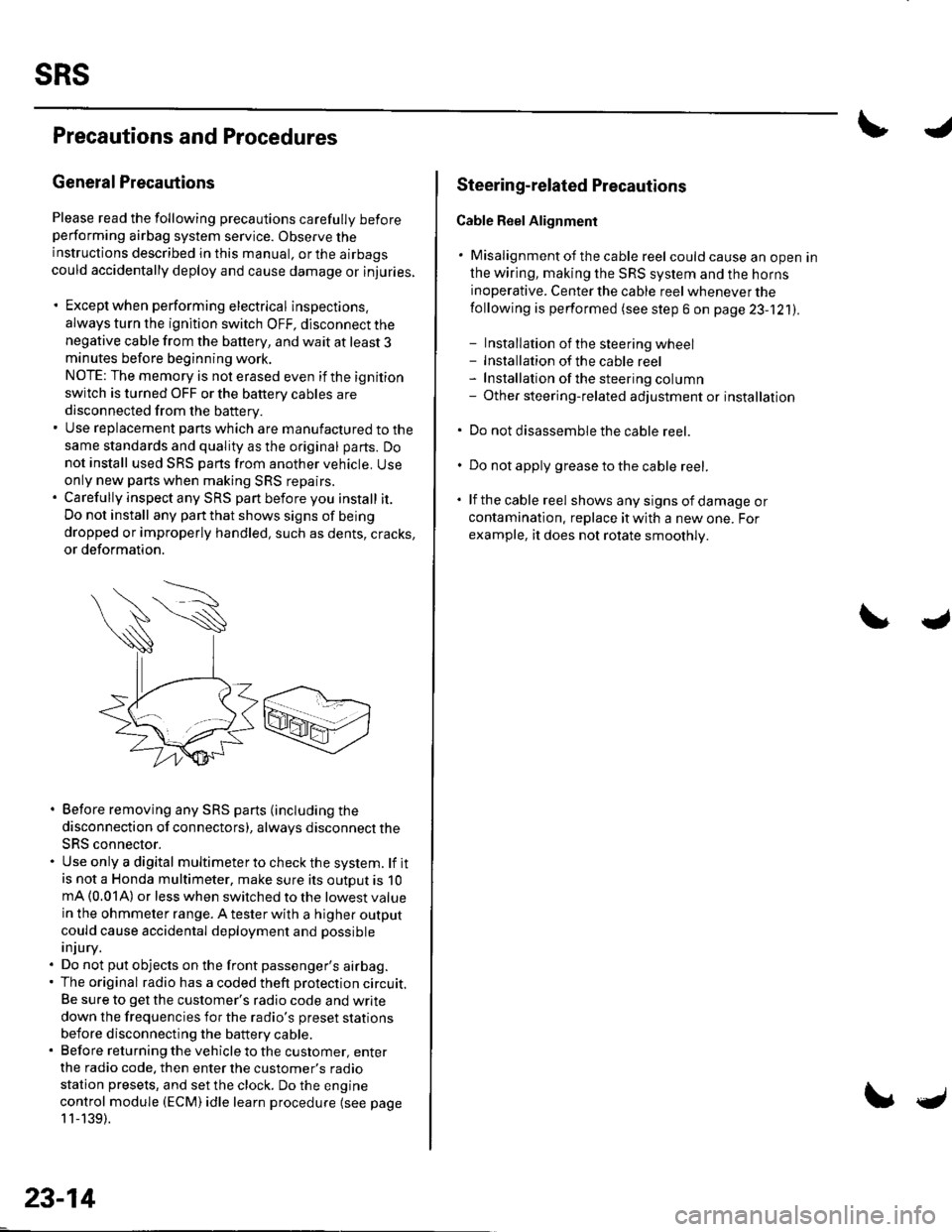
Please read the following precautions carefully beforeperforming airbag system service. Observe theinstructions described in this manual. or the airbags
could accidentally deploy and cause damage or injuries.
. Except when performing electrical inspections.
always turn the ignition switch OFF, disconnect the
negative cable from the battery, and wait at least 3minutes before beginning work.
NOTE: The memory is not erased even if the ignition
switch is turned OFF or the battery cables are
disconnected from the battery.. Use replacement pans which are manufactured to the
same standards and quality as the original parts. Do
not install used SRS parts from another vehicle. Useonly new pans when making SRS repairs.. Carefully inspect any SRS part before you install it.
Do not install any part that shows signs of being
dropped or improperly handled, such as dents, cracks,
or deformation.
. Before removing any SRS parts (including the
disconnection of connectors), always disconnect the
SRS connector.. Use only a digital multimeter to check the system. lf itis not a Honda multimeter, make sure its outout is 10mA (0.01A) or less when switched to the lowest value
in the ohmmeter range. A tester with a higher output
could cause accidental deployment and possible
injury.. Do not put objects on the front passenger's airbag.. The original radio has a coded theft protection circuit.
Be sure to get the customer's radio code and write
down the frequencies for the radio's preset stations
before disconnecting the battery cable.. Before returning the vehicle to the customer, enter
the radio code. then enter the customer's radio
station presets, and set the clock. Do the engine
control module (ECM) idle learn procedure (see page
11-139).
23-14
c
Steering-related Plecautions
Cable Reel Alignment
. Misalignment of the cable reel could cause an open in
the wiring, making the SRS system and the horns
inoperative. Center the cable reel whenever the
following is performed (see step 6 on page 23-121).
- Installation of the steering wheel- Installation of the cable reel- Installation ofthe steering column- Other steering-related adjustment or installation
. Do not disassemble the cable reel.
. Do not apply grease to the cable reel.
. lf the cable reel shows any signs of damage or
contamination. replace it with a new one. For
example, it does not rotate smoothly.