2002 HONDA CIVIC airbag
[x] Cancel search: airbagPage 851 of 1139

Connectors and Harnesses
Engine Compartment Wire Harness (Left branch)
AirJuel (A,,/F) ratio sensorBrake fluid level switchCondenser fan motorCruise control actuatorELD unitFog light connectorLeft front ABS wheel sensorLeft front airbag sensorLeft front parking lightLeft front side marker lightLeft lrontturn signal lightLeft headlightLeft hornRadiator fan motorRadiator fan switchSecondary heated oxygen (SHO2S)
Test tachometer connectorWindshield wiper motorUnder'hood fuse/relay boxconnector A {see page 22-44)Under-hood f use/relay boxconnector B (see page 22-44)Under hood fuse/relay boxconnector C (see page 22-44)Under hood fuse/relay boxconnector D (see page 22 44)Under-hood fuse/relay box
Front of engine companmentLeft side of engine compartmentLeft side of engine compartmentLeft side o{ engine compartmentFront of engine compartmentUnder right side of cowl coverUnder'hood f use/relay boxLeft side of engine compartmentLeft side of engine companmentBehind left side of front bumperBehind left headlightBehind left side of front bumperEehind left headlightBehind left headlightBehind front bumperLeft side of engine compartmentFront of engine compartmentLeft side of engine compartment
Left side of engine companmentL.Jnder left side of cowl coverL.Jnder hood fuse/relay box
L.Jnder hood fuse/relay box
L.Jnder'hood f use/relay box
underhood fuse/relay box
Under-hood fuse/relay box
24222
2519
12
17
13202123
3
117
I
10
5
6
l2
2243,l
222223l224
252
5
12
Connector to Harness Index (cont'dl
\
22-20
Page 861 of 1139

Connectors and Harnesses
Connector to Harness Index (cont'd)
Dashboard Wire Harness B
Collqctor or TerminalCavitiesLocatiol|ConnectstoNotesCableCombination light switchDriver's airbag inflatorlgnition key switchlgnition switchlmmobilizer control unit receiverPassenger's airbag inf latorSRS unit connector AWiper/washer switchUnder dash fuse/relay boxconnectorA lsee page 22,45)Under dash luse/relay boxconnector B (see page 22-45)Under'dash fuse/relay boxconnector C (see page 22-45)Under-dash fuse/relay boxconnector S lsee page 22-45)Under'dash fuse/relay boxconnectorX (see page 22 45)c401
c402
c403
G510
reel211716't9
18I
35
6
1
8
10
12
11
14
5
4
11418145
6
14
2
8
10
4
12
In steering column coverIn steering column coverIn steering column coverIn steering column coverIn steering column coverIn steering column coverUnder middle of dashUnder middle ofdashIn steering column coverUnder left side of dash
Under left side ofdash
Under left side of dash
Under lett side of dash
Under left side of dash
Under right side of dash
Under middle of dash
Under middle of dash
Under middle side of dash
Engine compartment wireharness (see page 22-'18)Floor wire harness (see page22-34JFloor wire harness (see page22-341Dashboard wire harness A(see oaoe 22-26)G40lUnder gauge assemblyBody ground via dashboard
22-30
Page 865 of 1139

Connectors and Harnesses
Connector to Harness lndex (cont'd)
Floor Wire Harness (Front sidel
Connec-tor or TerminalI Refuavftres Location connects to Nol6sDriver's seat belt switchDriver's side airbag inflatorDriver's side impact sensorLeft side seat belt buckle tensionerMemory erase signal (MES) connectorParking brake switchPassenger's seat belt switchPassenger's side airbag inflatorPassenger's side impact sensorRight side seat belt buckle tensionerSRS unit connector BSRS unit connector CUnder-dash fuse/relay boxconnector P {see page 22-45)Under-dash fuse/relay boxconnector O (see page 22,45)c402
c403
c453
c508
c509
c512
11l013121995374202111
'r8
22
23
2
14
1
6
3 I Under driver's seat2 i Under driver's seat2 I Left side offloor4 Under driver's seat2 Under dash fuse/relay box1 1 Middle offloor3 Under passenger's seat2 Under passenger's seat2 Right side offloor4 Under passenger's seat18 I Under middle of dash8 Under middle of dash18 Underdash fuse/relay box
8
]
Under dash fuse/relay box
10
I
Under middle of dash
4 Under middle of dash
6 Under middle of dash
4 Under middle of dash
6 Under middle ofdash
8
I
Under middle of dash
10 Under middle of dash
4 ] Unaer middle of aasn
Dashboard wire harness B{see page 22 30)Dashboard wire harness B(see page 22-30)ECM wire harness (see page22-321Dashboard wire harness A(see page 22-26)Dashboard wire harness A\see page 22-26)Dashboard wire harness A{see page 22-26)Engine compartment wireharness (see page 22 18)OPDS unit harness (see page22-421G551IL,nder passenger's seatBody ground via floor wire
22-34
Page 1009 of 1139
I
I
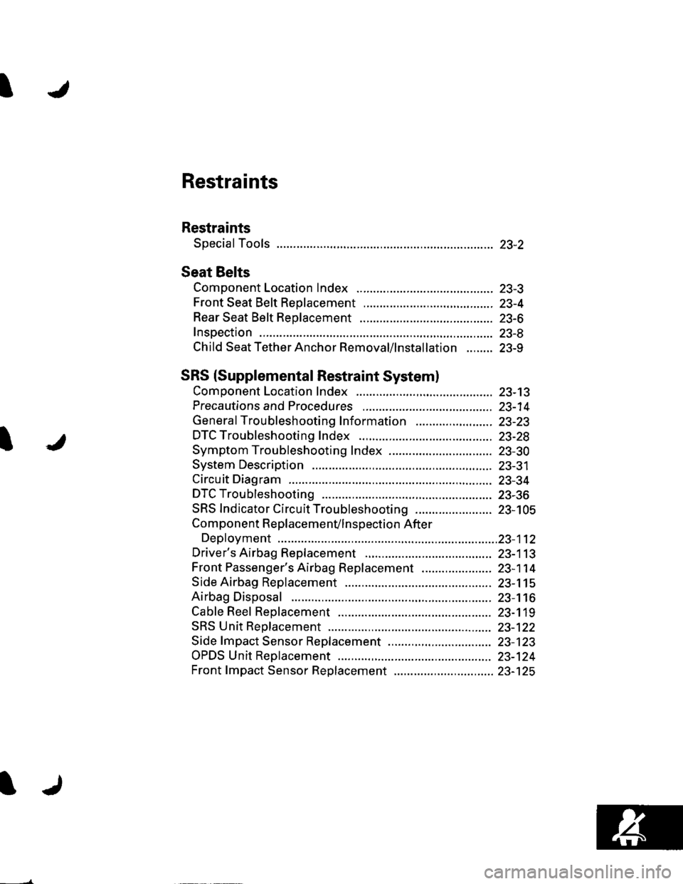
Restraints
Restraints
Special Tools ............. 23-2
Seat Belts
Component Location Index ......................................... 23-3
Front Seat Belt Replacement ....................................... 23-4
Rear Seat Belt Replacement ........................................ 23-6
Inspection .................. 23-8
Child Seat Tether Anchor Removal/lnstallation ........ 23-9
SRS (Supplemental Restraint Systeml
Component Location Index ......................................... 23-13
Precautions and Procedures ,,.,......... 23-14
General Troubleshooting Information ....................... 23-23
DTC Troubleshooting Index .............. 23-28
Symptom Troubleshooting Index ............................... 23-30
System Description ................. ........... 23-31
Circuit Diagram ......... 23-34
DTC Troubleshooting ............... .......... 23-36
SRS Indicator Circuit Troubleshooting ....................... 23-105
Component R e place me n(/ln s pect io n After
Deployment ..............23-112
Driver's Airbag Replacement ............ 23-113
Front Passenger's Airbag Replacement ..................... 23-1 14
Side Airbag Replacement .................. 23-115
Airbag Disposal ....................... ........... 23-116
Cable Reel Replacement .................... 23-119
SRS Unit Repfacement ....................... 23-122
Side fmpact Sensor Replacement ..........,.................... 23-123
OPDS Unit Replacement .................... 23-124
Front fmpact Sensor Replacement .............................. 23-125
Page 1020 of 1139
sRs
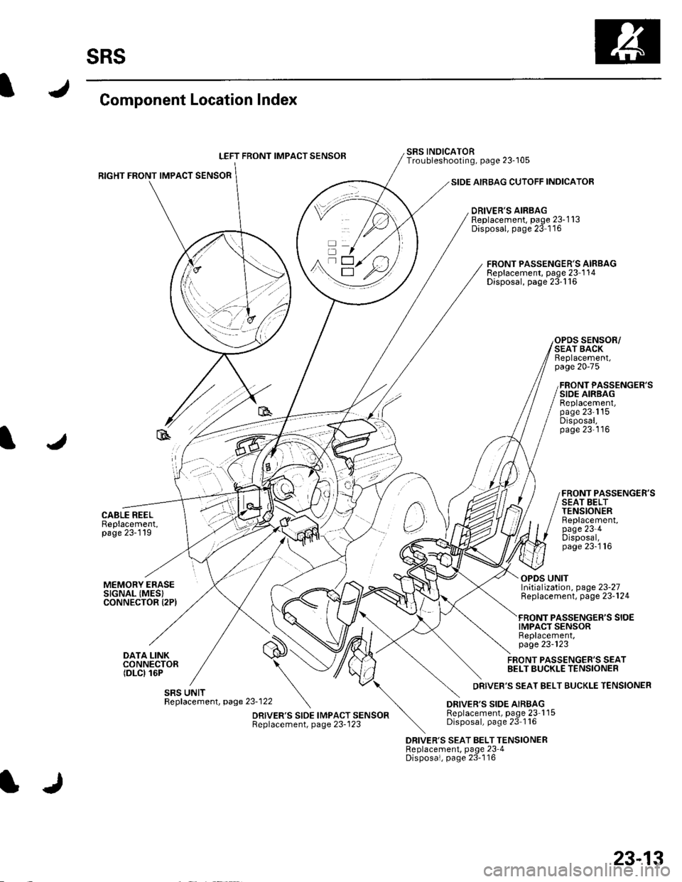
Component Location Index
LEFT FRONT IMPACT SENSOB
RIGHT FRONT IMPACT SENSOR
CABLE REELBeplacement,page 23-119
SIDE AIRBAG CUTOFF INDICATOR
DRIVER'S AIRBAGReplacement, page 23-1 13Disposal, page 23 1'16
SRS INOICATORTroubleshooting, page 23-105
FRONT PASSENGER'S AIRBAGReplacement, page 23-1 14Disposal, page 23'116
SENSOR/SEAT BACKReplacement,page 20-75
FRONT PASSENGER'SSIDE AIRBAGReplacement,page 23'1'15Disposal,page 23'116
FRONT PASSENGER'SSEAT BELTTENSIONERBeplacement,page 23-4Disposal,page 23-'116
MEMORY ERASESIGNAL (MES}CONNECTOR I2PI
DATA LINKCONNECTOR(DLCI 16P
OPDS UNITInitialization, page 23-27Replacement, page 23-124
PASSENGER'S SIOEIMPACT SENSORReplacement,page 23-123
FRONT PASSENGER'S SEATBELT BUCKLE TENSIONER
DRIVER'S SEAT BELT TENSIONERReplacement, page 23 4Disposal, page 23-116
23-13
Page 1021 of 1139
sRs
Precautions and Procedures
General Precautions
Please read the following precautions carefully beforeperforming airbag system service. Observe theinstructions described in this manual. or the airbags
could accidentally deploy and cause damage or injuries.
. Except when performing electrical inspections.
always turn the ignition switch OFF, disconnect the
negative cable from the battery, and wait at least 3minutes before beginning work.
NOTE: The memory is not erased even if the ignition
switch is turned OFF or the battery cables are
disconnected from the battery.. Use replacement pans which are manufactured to the
same standards and quality as the original parts. Do
not install used SRS parts from another vehicle. Useonly new pans when making SRS repairs.. Carefully inspect any SRS part before you install it.
Do not install any part that shows signs of being
dropped or improperly handled, such as dents, cracks,
or deformation.
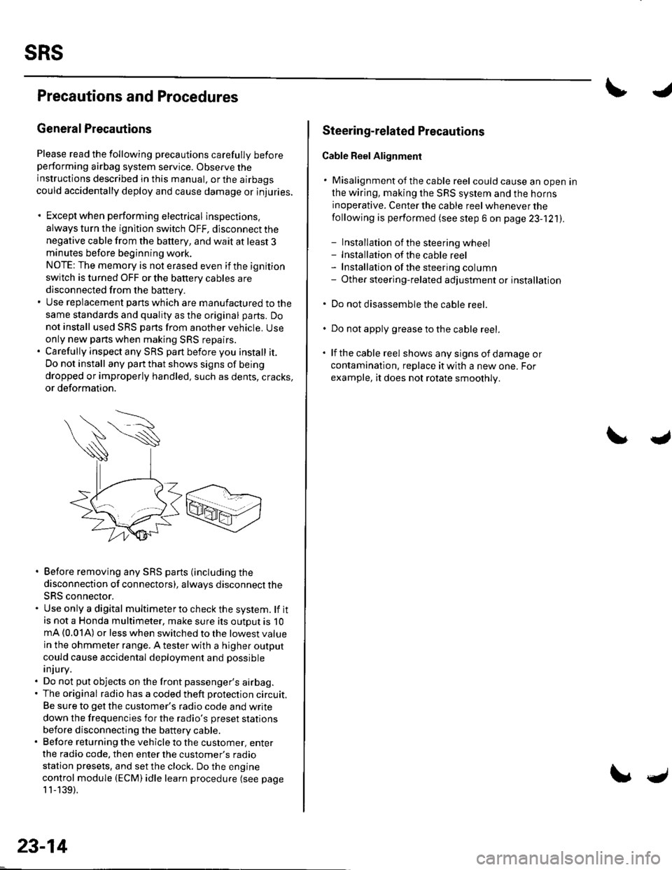
. Before removing any SRS parts (including the
disconnection of connectors), always disconnect the
SRS connector.. Use only a digital multimeter to check the system. lf itis not a Honda multimeter, make sure its outout is 10mA (0.01A) or less when switched to the lowest value
in the ohmmeter range. A tester with a higher output
could cause accidental deployment and possible
injury.. Do not put objects on the front passenger's airbag.. The original radio has a coded theft protection circuit.
Be sure to get the customer's radio code and write
down the frequencies for the radio's preset stations
before disconnecting the battery cable.. Before returning the vehicle to the customer, enter
the radio code. then enter the customer's radio
station presets, and set the clock. Do the engine
control module (ECM) idle learn procedure (see page
11-139).
23-14
c
Steering-related Plecautions
Cable Reel Alignment
. Misalignment of the cable reel could cause an open in
the wiring, making the SRS system and the horns
inoperative. Center the cable reel whenever the
following is performed (see step 6 on page 23-121).
- Installation of the steering wheel- Installation of the cable reel- Installation ofthe steering column- Other steering-related adjustment or installation
. Do not disassemble the cable reel.
. Do not apply grease to the cable reel.
. lf the cable reel shows any signs of damage or
contamination. replace it with a new one. For
example, it does not rotate smoothly.
Page 1022 of 1139
Airbag Handling and Storage
Do not disassemble an airbag, lt has no serviceable
parts. Once an airbag has been deployed, it cannot be
repaired or reused.
For temporary storage of an airbag during service,
observe the following precautions.
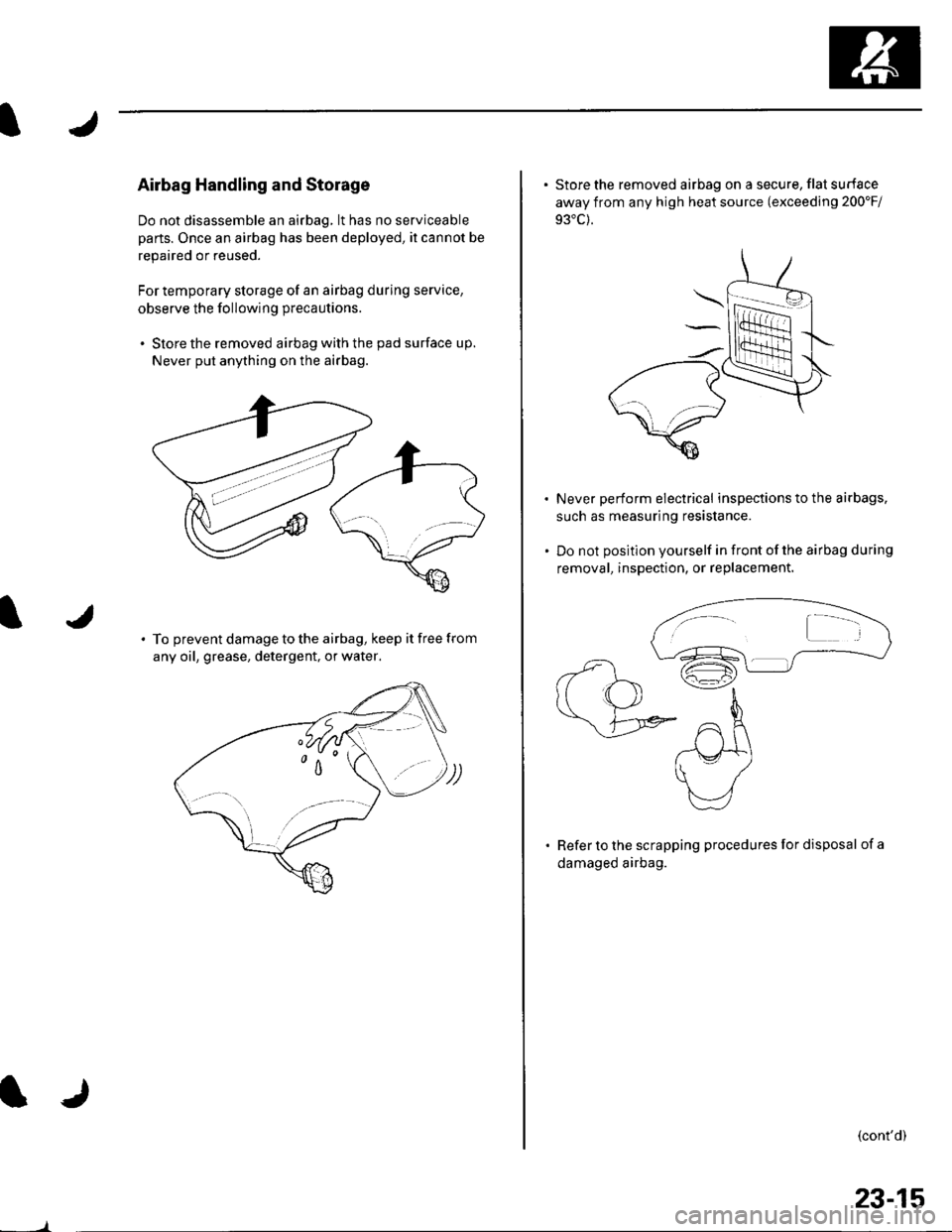
. Store the removed airbag with the pad surface up.
Never put anything on the airbag.
To prevent damage to the airbag, keep it free from
any oil, grease, detergent, or water,
23-15
. Store the removed airbag on a secure, flat surface
away from any high heat source (exceeding 200'Fi
Never perform electrical inspections to the airbags,
such as measuring resistance.
Do not position yourself in front of the airbag during
removal, inspection, or replacement.
Refer to the scrapping procedures for disposal of a
damaged airbag.
(cont'd)
Page 1023 of 1139
sRs
Precautions and Procedures {cont'dl
SRS Unit, Front lmpact Sensors, and Side
lmpact Sensors
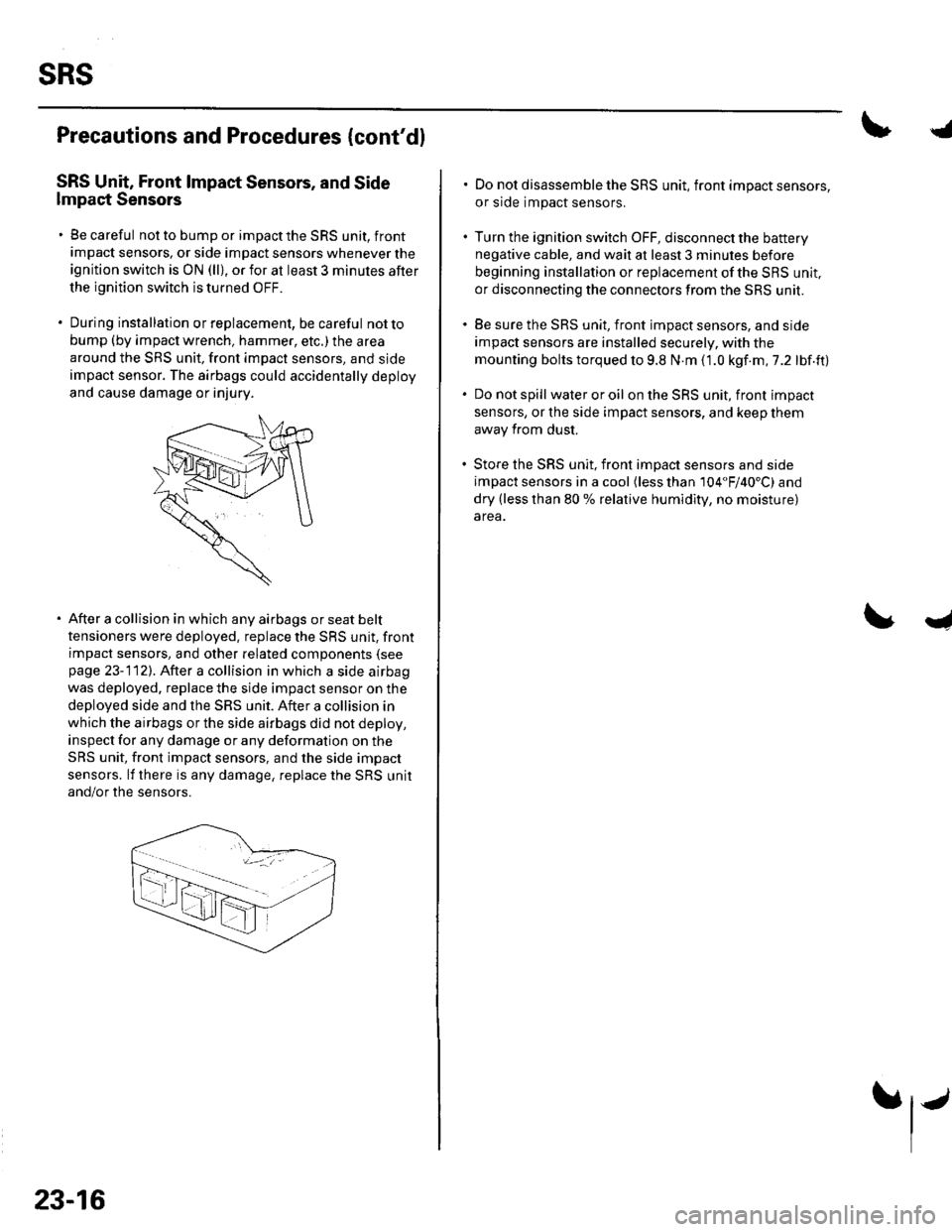
. Be careful not to bump or impact the SRS unit, front
impact sensors, or side impact sensors whenever the
ignition switch is ON (ll), or for at least 3 minules after
the ignition switch is turned OFF.
. During installation orreplacement, be careful notto
bump (by impact wrench, hammer, etc.) the area
around the SRS unit, front impact sensors, and sjde
impact sensor. The airbags could accidentally deploy
and cause damage or injury.
After a collision in which any airbags or seat belt
tensioners were deployed. replace the SRS unit, front
impact sensors, and other related components (see
page 23-112). After a collision in which a side airbag
was deployed. replace the side impact sensor on the
deployed side and the SRS unit. After a collision in
which the airbags or the side airbags did not deploy,
inspect for any damage or any deformation on the
SRS unit, front impact sensors, and the side impact
sensors. lf there is any damage, replace the SRS unit
and/or the sensors.
23-16
.j
. Do not disassemble the SRS unit, front impact sensors,
or side impact sensors.
. Turn the ignition switch OFF, disconnect the battery
negative cable, and wait at least 3 minules before
beginning installation or replacement of the SBS unit,
or disconnecting the connectors from the SRS unit.
. Be sure the SRS unit, front impact sensors, and side
impact sensors are installed securely. with the
mounting bolts torqued to 9.8 N.m (1.0 kgf.m,7.2 lbf.ft)
. Do not spill wateroroil on the SRS unit, front impact
sensors, or the side impact sensors, and keep them
away from dust.
. Store the SRS unit, front imDact sensors and side
impact sensors in a cool (less than 104"F/40'C) and
dry (less than 80 % relative humidity, no moisture)
area.
I