Page 91 of 1139
7. Loosely tighten the front mount bracket mounting
bolt.
Lower the hoist.
Tighten the upper bracket mounting bolt and nut.
8.
9.
10. Tighten the transmission mount bracket support
bolt and nuts.
12 x 1.25 mm54 N m {5.5 kgt m, 40 lbf.ft}
Raise the hoist to full height.
Tighten the front engine mount bracket mounting
bolt.
'l '1.
't2.
12 x 1.25 rnrn64 N.m {6.5 kgf.m,47 tbt.ftl
13. Lower the hoist.
14. Remove the chain hoist from the engine.
'15. Installthe radiator (see page 10-10).
'16. Raise the hoist to full height.
17. Install a new set ring on the end of each driveshaft,
then install the driveshafts. Make sure each ring"clicks" into place in the differential and
intermediate shaft.
(cont'd)
:l
5-11
Page 95 of 1139

40. Install the air cleaner housinq.
6x1.0mm12 N m (1.2 kgf.m,8.7 lbt.ft)
Install the air cleaner housing cover (A) and
connect the intake air temperature (lAT) sensor
connector (B),
42. Installthe breather hose (C) and vacuum hose 1D).
41.
43. Installthe intake manifold cover.
6x1.0mm12Nm11.2kgf.m.8.7 tbf.ft)
Installthe battery. Clean the battery posts and
cable terminals with sandpaper, then assemble
them and apply grease to prevent corrosion.
Check that the transmission shifts into gear
smoothly.
Inspect for fuel leaks. Turn the ignition switch ON(ll) {do not operate the starter) so that the fuel pump
runs for about 2 seconds and pressurizes the fuel
line. Repeat this operation two or three times, then
check for fuel leakage at any point in the fuel line.
Refillthe engine with engine oil (see page 8-5).
Refill the transmission with fluid (see page 13-3).
Refill the radiator with engine coolant, and bleed
air from the cooling system with the heater valve
open (see page 10-6).
Perform the engine control module (ECM) idle learnprocedure (see page 11-139).
Inspect the idle speed (see page 1 1-138).
Inspect the ignition timing (see page 4-17).
Check the wheel alignment {see page 18-4).
Enter the anti-theft code for the radio, then enter
the customer's radio station presets.
Set the clock.
YE
44.
41.
]tE
46.
48.
49.
52.
53.
54.
50.
51.
55.
5-15
Page 139 of 1139

Engine Mechanical
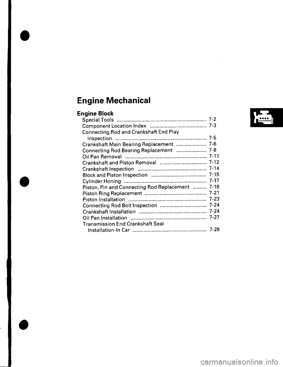
Engine Block
Soecial Tools ............. 7 -2
Comoonent Location Index ......................................... 7-3
Connecting Rod and Crankshaft End Play
InsDection .............. 7-5
Crankshaft Main Bearing Replacement ...................... 7-6
Connecting Rod Bearing Replacement ...................... 7-8
Oil Pan Removal ....................... .......... 7-11
Crankshaft and Piston Removal ........ 7-12
Crankshaft Inspection ........................ 7-14
Block and Piston Insoection ........................................ 7-15
Cyfinder Honing ............ .".................... 7 -'17
Piston, Pin and Connecting Rod Replacement .......... 7-18
Piston Ring Replacement ................... 7 -21
Piston lnstallation .................... ........... 7-23
Connecting Rod Bolt Inspection .......' 7 -24
Crankshaft lnstallation .....................'. 7-24
Oil Pan lnstallation .................. ........... 7 -27
Transmission End Crankshaft Seal
lnstallation-ln Car ................... ........' 7 -28
Page 141 of 1139
Component Location Index
MAIN BEARINGSOilclearance, page 7-6Selection, page 7-6
CRANKSHAFTEnd play, page 7-5Runout, page 7-14Out-of-Round, page 7-14Removal, page 7-12lnstallation, page 7-24
fifr"8
-4
E
I
BAFFLE PLATE
LOWER BLOCK
FLYWHEEL
CRANKSHAFT OIL SEAL.TRANSMISSION ENDInstallation, step 21 on page 7-26
THRUST WASHERS
(cont'd)
7-3
Page 150 of 1139
Engine Block
Crankshaft and Piston Removal
1. Remove the engine assembly (see page 5-2).
2. Remove the transmission (see page 13-4).
3. Remove the oil pan (see page 7-1 1).
4. Remove the oil pump {see page 8-9).
5. Remove the cylinder head (see page 6-23).
6. Remove the baffle plates.
7. Remove the 8 mm bolts.
E
7-12
8. Remove the bearing cap bolts. To prevent warpage,
unscrew the bolts in sequence 1/3 turn at a time:
repeat the sequence until all bolts are loosened.
Remove the lower block and bearings, Keep all
bearings in order.
\L
(
Page 165 of 1139
23. Install the baffle plates.
6x1.0mm12 N.m(1.2 ksf m, 8.7 lbf ft)
24. Installthe oil pump (see page 8-14).
25. Installthe oil pan (see page 7-27).
26. Installthe cylinder head (see page 6-39).
27. Installthe transmission (see page 13-8).
28. Installthe engine assembly (see page 5-9).
1.
OilPan lnstallation
Remove old liquid gasket from the oil pan mating
surfaces, bolts, and bolt holes.
Clean and dry the oil pan mating surfaces.
Apply liquid gasket, P/N 08718-0009, evenly to the
cylinder block mating surface of the oil pan and to
the inner threads of the bolt holes.
NOTE: Do not install the parts if 5 minutes or more
have elapsed since applying liquid gasket. Instead,
reapply liquid gasket after removing old residue.
Installthe oil pan.
Tighten the bolts in two or three steps. In the final
step, tighten all bolts, in sequence, to 12 N.m (1.2
kgf m, 8.7 lbf.ft).
(cont'd)
2.
3.
4.
5.
Apply liquid gasketalong the broken line.
(}@
7-27
Page 166 of 1139

Engine Block
Oil Pan Installation (cont'dl
6. lf the engine is still in the vehicle, install the
subframe,
-1 Installthe subframe. Align the reference lines
on the subframe with the bolt head center, then
tighten the bolts (see step 5 on page 5-10).-2 Tighten the front mounting bolt (see step 6 onpage 5-10).-3 Tighten the rear mount mounting bolts (see
step 7 on page 5-11).-4 Connect the suspension lower arm ball joints
(see step 6 on page 18-19).
7. After assembly, wait at least 30 minutes before
filling the engine with oil.
7-28
v
Transmission End Grankshaft Seal
Installation - In Car
Special Tools Required. Driver 07749-0010000. Oil seal driver attach ment 96 07ZAD-PNAA100
'1. Dry the crankshaft oil seal housing.
2. Use the special tools to drive a new oil seal
squarely into the block to the specified installed
height.
07749-0010000
and oil seal (B).
Oil Seal Installed Height:
5.5 6.5 mm 10.22-0.26 in.l
5.5 6.5 mml0.22- O.26 in .l
I
/$rRfr4T
tr*W(r
-]t
fl\OTZAD.PNAAlOO
Measure the distance between the crankshaft (A)
a
Page 239 of 1139

Fuel and Emissions Systems
(
{
System Descriptions (cont'd)
ldle Control System
When the engine is cold, the Ay'C compressor is on, the
transmission is in gear, the brake pedal is pressed. thepower steering load is high, or the alternator is
charging, the ECIM controls current to the ldle Air
Control (lAC) valve to maintain the correct idle speed.
Refer to the System Diagram to see the functional
layout of the system.
Brake Pedal Position Switch
The brake pedal position switch signals the ECM when
the brake pedal is oressed.
Electrical Power Steering (EPS) Senser
The EPS sensor signals the ECM when the power
steering load is high.
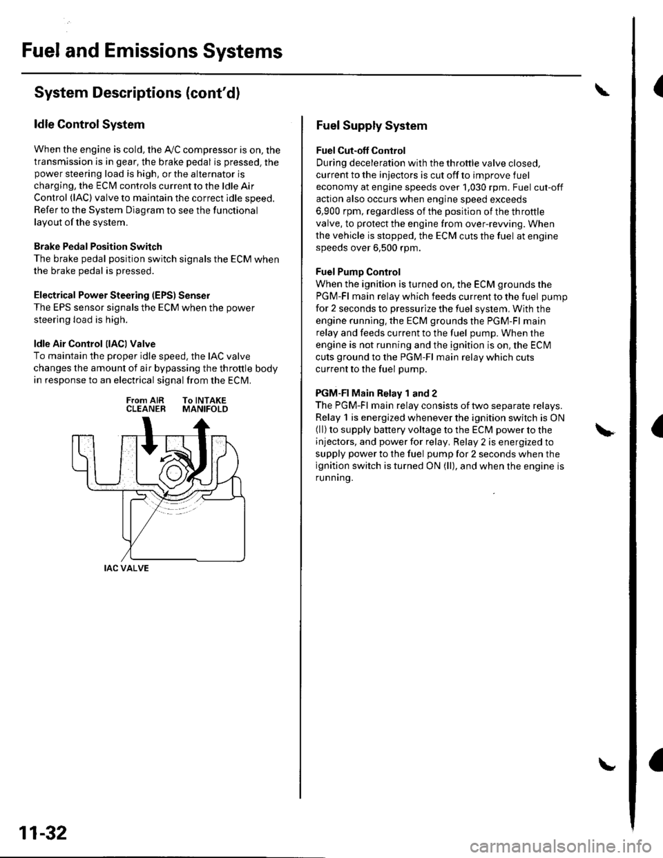
ldle Air Control llACl Valve
To maintain the proper idle speed, the IAC valve
changes the amount of air bypassing the throttle body
in response to an electrical signal from the ECM.
From AIR To INTAKECLEANER MANIFOLD
IAC VALVE
11-32
Fuel Supply System
Fuel Cut-off Control
During deceleration with the throttle valve closed,
current to the injectors is cut off to improve fuel
economy at engine speeds over 1,030 rpm. Fuel cut-off
action also occurs when engine speed exceeds
6,900 rpm, regardless of the position of the throttle
valve, to protect the engine from over-rewing. When
the vehicle is stopped. the ECM cuts the fuel at engine
speeds over 6,500 rpm.
Fuel Pump Control
When the ignition is turned on, the ECM grounds the
PGM-Fl main relay which feeds current to the fuel pump
for 2 seconds to pressurize the fuel system, With the
engine running. the ECM grounds the PGM-Fl main
relay and feeds current to the fuel pump. When the
engine is not running and the ignition is on, the ECI\4
cuts ground to the PGM-Fl main relay which cuts
current to the fuel pump.
PGM-FI Main Relay 1 and 2
The PGM-Fl main relay consists of two separate relays.
Relay 1 is energized whenever the ignition switch is ON(ll) to supply battery voltage to the ECM power to the
injectors, and power for relay, Relay 2 is energized to
supply power to the fuel pump for 2 seconds when the
ignition switch is turned ON (ll), and when the engine is
runnrng.