2002 HONDA CIVIC ground
[x] Cancel search: groundPage 997 of 1139

lmmobilizer System
Troubleshooting (cont'dl
8. Check for voltage betvveen the immobilizer control
unit-receiver 7P connector No. 6 terminal and No. 1
rermlnat.
ls thete battery voltage?
YES Go to step 12.
NO Check for these problems,
. Open on the BRNI/EL wire.l. Faulty ECM.I
9. Remove the driver's dashboard lower cover (see
page 20-59).
10. Remove the steering column lower cover (see page
17-9).
11. Disconnect the 7P connector (A) from the
immobilizer control unit-receiver (B).
22-166
-
Check for continuity between the immobilizer
control unit-receiver 7P connector No. 2 terminal
and ECM terminal E27.
ls there continuity?
YES-Go to step 13.
NO- Repair the open in the RED/BLU wire.I
Reconnect the 7P connector to the immobilizer
control unit-receiver.
Check for voltage between the immobilizer control
unit-receiver 7P connector No. 4 terminal and body
ground with the parking brake lever pulled, then
released.
ls there 1 V or less, then 5 V or more?
YES Replace the immobilizer control unit-receiver.
After replacing the immobillzer control unit-
receiver, rewrite the unit with a Honda PGM
Tester.l
NO Check for these problems:
. Faulty parking brake switch or a poor body
ground of the parking brake switch.l. Repair short or open in the GRN/ORN wire. I
13.
14.
{
Page 1003 of 1139
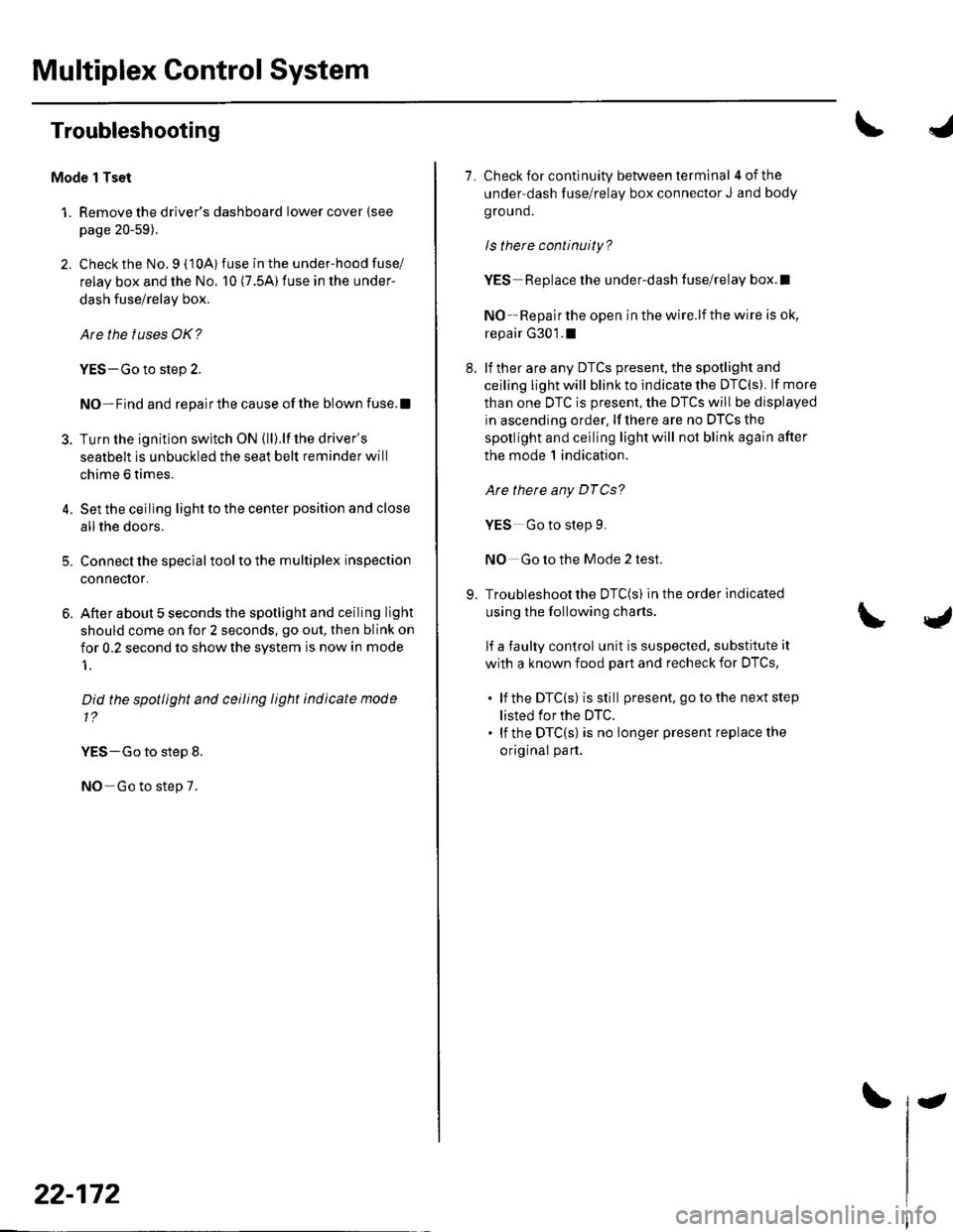
Multiplex Control System
Troubleshooting
Mode 1 Tset
1. Remove the driver's dashboard lower cover {see
page 20-59).
2. Check the No. 9 ( 10A) fuse in the under-hood fuse/
relay box and the No. 10 (7.5A) fuse in the under-
dash fuse/relay box.
Are the fuses OK?
YES-Go to step 2.
NO-Find and repairthe cause ofthe blown fuse.!
3. Turn the ignition switch ON (ll).lf the driver's
seatbelt is unbuckled the seat belt reminder will
chime 6 times.
4. Set the ceiling light to the center position and close
allthe doors.
5. Connect the specialtoolto the multiplex inspection
conneclor.
6. After about 5 seconds the spotlight and ceiling light
should come on for 2 seconds, go out, then blink on
for 0.2 second to show the system is now in mode
1.
Did the spotlight and ceiling light indicate mode
1?
YES-Go to step 8.
NO Go to step 7.
22-172
-
7. Check for continuity between terminal 4ofthe
under-dash fuse/relay box connector J and body
ground.
ls there continuity?
YES Replace the under-dash fuse/relay box.l
NO - Repair the open in the wire.lf the wire is ok,
repair G301.1
8. lf ther are any DTCS present, the spotlight and
ceiling light will blink to indicate the DTC(S). lf more
than one DTC is present, the DTCS will be displayed
in ascending order, lf there are no DTCS the
spotlight and ceiling light will not blink again after
the mode 1 indication.
Are there any DTCg?
YES Go to step 9.
NO Go to the Mode 2 test.
9. Troubleshoot the DTC(S) in the order indicated
using the following charts.
lf a faulty control unit is suspected, substitute it
with a known food part and recheck for DTCS,
. lf the DTC(s) isstill present. go to the next step
listed for the DTC.. lf the DTC(S) is no longer present replace the
original part.
Page 1004 of 1139
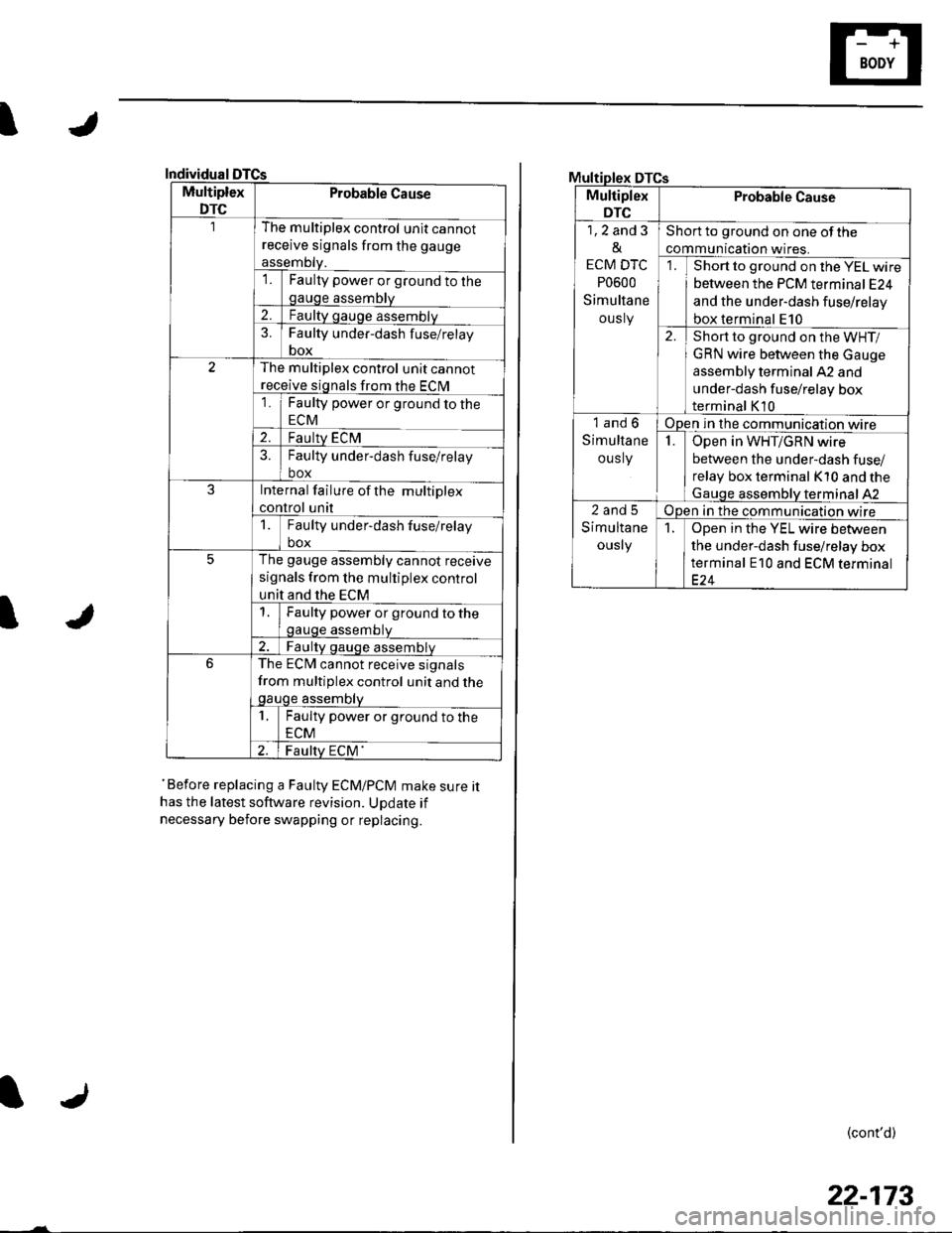
I
Individual
Multiplex
DTC
Probable Cause
The multiplex control unit cannot
receive signals from the gauge
assemDty.'lFaulty power or ground to thegauge assembly
2.Faulty gauge assemblv
3.Faulty under-dash f use/relay
box
The multiplex control unit cannot
receive signals from the ECM
1Faulty power or ground to the
ECM
2.Faulty ECM?Faulty under-dash fuse/relay
box
JInternal failure of the multiplex
control unit
1Faulty under-dash fuse/relay
box
5The gauge assembly cannot receive
signals from the multiplex control
unit and the ECM
Faulty power or ground to thegauge assembtv
Faulty qauge assemblv
6The ECM cannot receive signals
from multiplex control unit and thegauge assembty
1Faulty power or ground to the
ECM
Faulty ECM'
I
'Before replacing a Faulty ECM/PCM make sure ithas the latest software revision. UDdate if
necessary before swapping or replacing.
DTCs
Multiplex
DTC
Probable Cause
1,2 and 3
&
ECM DTC
P0600
Simultane
ously
Short to ground on one of the
communication wires.
Short to ground on the YEL wire
between the PCM terminal E24
and the under-dash fuse/relay
box terminal E10
2.Short to ground on the WHT/
GRN wire between the Gauge
assembly terminal A2 and
under-dash fuse/relay box
terminal K10
1and6
Simultane
ous ly
Open in the communication wire
IOpen in WHT/GRN wire
between the under-dash fuse/
relay box terminal K10 and the
Gauqe assemblV terminal 42
2and5
Simultane
ously
Open in the communication wire
1Open in the YEL wire between
the under-dash fuse/relay box
terminal E10 and ECM terminal
(cont'd)
22-173
Page 1007 of 1139
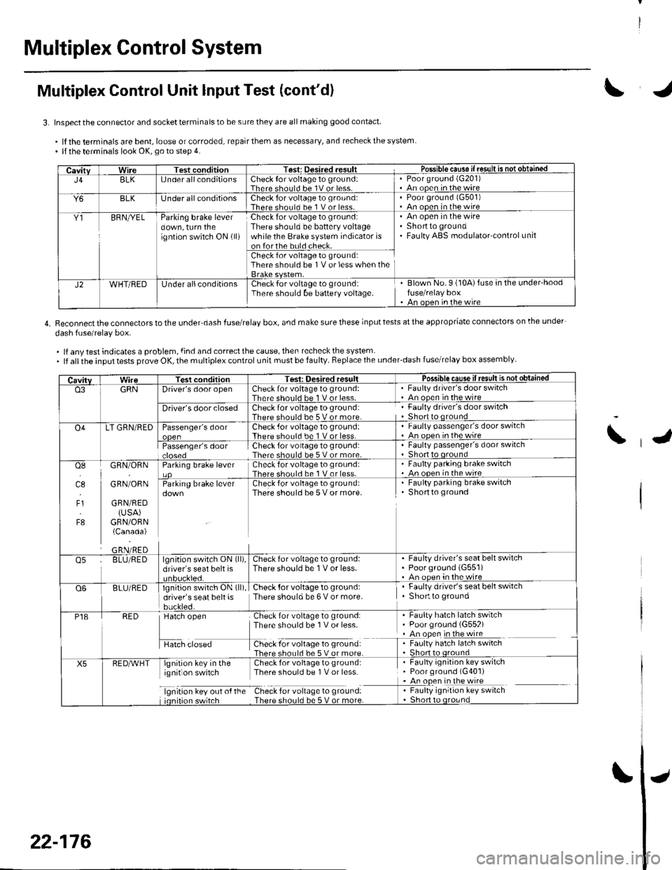
Multiplex Control System
Multiplex Control Unit lnput Test (cont'd)
3. Inspect the connector and socket terminals to be sure they are all making good contact
.lftheterminalsarebent,looseorcorroded,repairthemasnecessary,andrecheckthesystem. llthe terminals look OK, go to step 4.
4. Reconnectthe connectorstothe under dash fuserelay box, and make surethese inputtests atthe appropriate connectors on lhe under-
dash fuse/relav box.
. lf any test indicates a problem, {ind and correct the cause, then recheck the system. lf allthe input tests prove OK, the multiplex control unit must be faulty. Replace the under_dash fuse/relay box assembly
CavitvWireTest conditionTest: Desired .esult r Possible cause if resullE qS!q!!e!!ed
J4BLK[J nder all conditionsCheck {or voltage 1o ground:Therc sholl.l he 1V or lessPoor ground (G20'l)An ooen in the wire
Y6BLKlJnder all conditionsCheck for voltage to ground:There should bc 1 V or less.Poor ground 1G501)An ooen in the wire
Y1BFNryELParking brake leverdown, turn theigntion switch ON (ll)
Check for voltage to ground:There should be battery voltagewhile the Brake system indicator ison forthe buld check.
An open in the wireShortto groundFaulty ABS modulatorcontrol unit
Check for voltage to ground:There should be 1V or less when the
J2WHT/REDUnder allconditionsCheck for voltage to groundiThere should be baftery voltage.Blown No.9 (10A)fuse in the under'hoodfuse/relay boxAn oncn in rhc wire
CavitvTest conditionTesi: Oesired resultPossible cause ifresult is notobtained
o3GRNDriver's door openCheck for voltage to ground:There should be 1 V or less-Faulty driver's door switchAn ooen in the wire
Driver's door closedCheck for voltage to ground:There should be 5 V or more.Faulty driver's door switchShort to qround
O4LT GRN/REDPassenger's doorCheck .for voltage 10 ground:There should be 1 V or less.Faulty passenger's door switchAn ooen inthewire
Passenger's doorCheck for voltage to ground:There should be 5 V or more.Faulty passenger's door switchShort to oround
osI]l.l
4.,
F1
F8
GRN/ORN
GRN/ORN
GRN/RED(USA)GRN/ORN(Canada)
Parking brake leverCheck for voltage to groLrnd:There shorl.l be 1 V or less.Faulty parking brake switch. An ooen in thewireCheck for voltage to ground:There should be 5 V or more.
. Faulty parking brake switchShortto ground
o5BLU/REDlgnition switch ON (ll),
driver's seat belt isCheck for voltage to ground:There should be 1V or less.Faulty driver's seat belt switchPoorground (G551)An oDen in the wire
Q6BLU/REDlgnition switch ON (ll)
driver's seat belt isbuckled.
Check {or voltage to ground:There should be 6 V or more.Faulty driver's seat belt switchShortto ground
P18RED
H",=
Check for voltage to ground:There sho0ld be 1V or less-
f -9*:li:'^:**:':s*:*
Faulty hatch latch swrtchPoor ground (G552)An open in the wireFaulty hatch latch switch
X5lgnirion key in the Check for voliage to gtound:ignit on switch Thpre should be I V or lcss
lgnrtron kev our o{ the Check for vollage to ground:
. Faulty ignition key switch. Poor ground (G401). An open in the wire
I : [11y.'::i':::1"' **6
\
22-176
Page 1008 of 1139
IJ
IJ
IJ
CavitvWireTest conditionTest: Desired resultPossible cause if resuk is not obtainedX8WHT/BLKUnder allconditionsAttach to ground:The ignition keylight should come on.Blown No.3 (7.5A)fuse in the under,hood
Blown LEDAn ooen in the wireo7GRN/REDCeiling light switch inthe middle position,all doors closed
Attach to ground:The ceiling light,spotlights should come on.Elown No. 3 (7.54)fuse in the undeFhood
Faulty ceiling lightAn oDen in the wirec]1BLU Under all conditionsAttach to ground: Dash lights shouldBlown No. 2 (15Aifuse in the under-hoodfuse/relay boxFaulty taillight relayAn ooen in the wireF8GRN/REDBrake fluid reservoirfloat in downposition (brake fluid
Check for voltage to ground:There should be less than I V.Faulty brake fluid level switchAn open in the wire
Brake lluid reservoirfloat in up position(brake fluid at fulllevel)
Check for voltage to ground:There should be 5 V or more.Faulty brake fluid level switchShortto ground
E10YELUnder all conditionsCheck for voltage to ground:There should be battery voltage inthe sleep mode and 3 Tvoltswhen
. An open or short in the wire
K10WHT/GRNUnder all conditionsCheck for voltage to ground:There should be battery voltage inthe sleep mode and 3 Tvoltswhen
An open or short in the wire
22-177
Page 1024 of 1139
I
J
Wiring Precautions
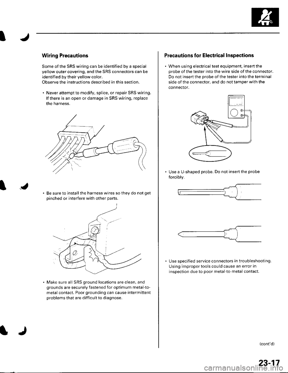
Some of the SRS wiring can be identified by a special
yellow outer covering, and the SRS connectors can be
identified by their yellow color.
Observe the instructions described in this section.
. Never attempt to modify. splice, or repair SRS wiring.
lf there is an open or damage in SRS wiring, replace
the harness.
Be sure to install the harness wires so they do not get
Dinched or interfere with other Darts.
Make sure all SRS ground locations are clean, and
grounds are securely fastened for optimum metal-to-
metal contact. Poor grounding can cause intermittent
problems that are difficult to diagnose.
Precautions for Electrical Inspections
. When using electricaltest equipment, insertthe
probe of the tester into the wire side of the connector.
Do not insert the probe of the tester into the terminal
side of the connector, and do not tamper with the
connector.
Use a U-shaped probe. Do not insert the probe
forcibly.
Use specified service connectors in tro u bleshooting.
Using improper tools cou ld cause an error in
inspection due to poor metal-to-metal contact.
(cont'd)
23-17
Page 1031 of 1139
sRs
General Troubleshooting Information (cont'd)
PGM Tester "SCS" Menu Method {retrieving the flash
codes):
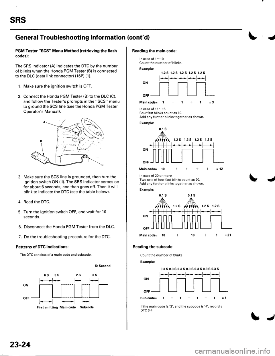
The SRS indicator (A) indicates the DTC by lhe number
of blinks when the Honda PGM Tester (B) is connected
to the DLC (data link connector) ( 16P) (1).
'1. Make sure the ionition switch is OFF.
2. Connect the Honda PGN4 Tester (B) to the DLC (C),
and follow the Tester's oromDts in the "SCS" menu
to ground the SCS line (see the Honda PGM Tester
ODerator's Manual).
Make sure the SCS line is grounded, then turn the
ignition switch ON (ll). The SRS indicator comes on
for about 6 seconds, and then goes off. Then it will
blink to indicate the DTC (see the table below).
Read the DTC.
Turn the ignition switch OFF, and wait for 10
seconds.
3.
4.
5.
6, Disconnect the Honda PGM Tester from the DLC.
7. Do the troubleshooting procedure for the DTC.
Patteins of DTC Indications:
The DTC consists of a main code and subcode.
S: Second
25 356S
oN
[ltl|[
oFFl I l------Ll---l I
First emitting Main code Subcode
23-24
\J
Reading the main code:
In case of 1- 10Count the number of blinks.
Examplo:1.2 S r.2 S 1.2 S 1.2 S 1.2 S
*t**t*l*l
""_f]_flfl
Maincodo= 1 + 1 + 1 =3
In case ot 11..'15Four fast blinks count as 10.Add any funher blinks together as shown.
Example:
0.1 s
,A/// t\\//lii 1.rs r.2s r.2s 1.2s
_ | *t* -L'--*l
Main code= 10 I
ln case of 20 or moreTwo sets of four fast blinks count as 20.Add any funher blinks together as shown.
Examplo:
0.1 s 0.1s
,y'fl\,,. /[N 12s 12s
=12
L4
""ffi
*FtftffN*+fH-t-ff *l-
Main code= 10 + 10
Reading the subcode:
Count the number of blinks.
Example:
0.3 s 0.3 s 0.3 s 0.3 s 0.3 s 0.3 s 0.3 s
l**t**t*t*t*l
""ffi
Subcode=1+1+1r'1=4
lf the main code is '3', and the subcode is '4', record aDTC 3 4.
Page 1032 of 1139
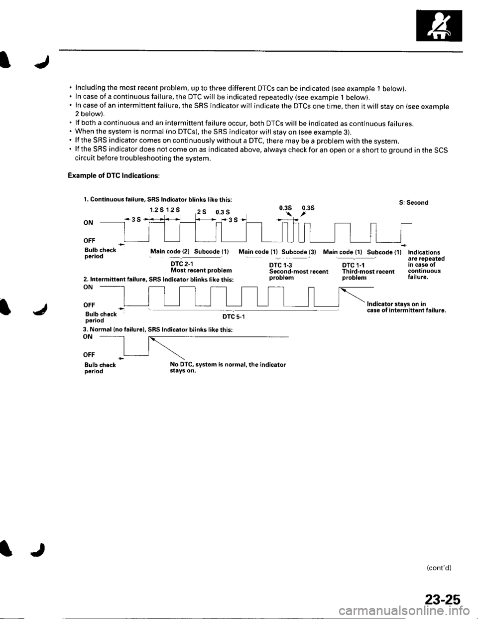
Including the most recent problem, up to three different DTCS can be indicated (see example 1 below).ln case of a continuous failure, the DTC will be indicated repeatedly {see example 1 below).In case of an intermittent failure, the SRS indicator will indicate the DTCS one time, then it will stay on (see example2 below).
lf both a continuous and an intermittent failure occur, both DTCS will be indicated as continuous failures.When the system is normal (no DTCS), the SRS indicator will stay on (see example 3).lf the SRS indicator comes on continuously without a DTC, there mav be a problem with the svstem.lf the SRS indicator does not come on as indicated above, always check for an open or a short to ground in the SCScircuit before troubleshooting the system.
Example of DTC Indications:
1. Continuous failure, SRS Indic6tor blink$ like this:
1.2 S 1,2 SS: Second0.3s 0.3s
ON
OFF
Bulb checkperiodMain code (21 Subcode l1)
DTC 2-lMost recent p.oblem
2. Intermittent failure, SRS lndicator blinks like this:ON
Main code l1lSubcode (3) Main code {11 Subcode {'l)Indicationsare lepeatedtn cese otcontinuousfailure.
lndicator stays on incase of i nterm ittent failu re.
(cont'd)
DTC 1-3DTC 1-1Sscond-mostrecent Third-mostrocentproblem problem
OFF
Bulb checkperiodDTC 5-1
3. Normal (no failure|, SRS Indicator blinks like this:ON
OFF
Bulb chockperiodNo DTC, systom is normal, the indicatorstays on.
0.3 s
23-25