Page 342 of 1139

15. Check for continuity between body ground and
ECIM connector terminal 813.
ECM CONNECTOR B I24P}
Wire side of female terminals
ls there continuity?
YES Repair short in the wire between the ECM
(813) and the alternator.l
NO Update the ECM if it does not have the latest
software, or substitute a known-good ECM, then
recheck lsee page 1 1-6). lf the symptom/indication
goes away with a known-good ECM, replace the
original ECM.I
Electrical Power Steering (EPSI
Signal Circuit Troubleshooting
Turn the ignition switch ON (ll).
l\4easure voltage between ECM connector
terminals 424 and E16.
1.
2.
3.
4.
5.
Wire side of female terminals
ls there battery voltage?
YES Go to step 6.
NO Go to step 3.
Start the engine.
Turn the steering wheel lo the full lock position.
l\4easure voltage between ECM connector
terminals A24 and E16.
ls there momentaty battery voltage?
YES The EPS signal is OK.t
NO Go to step 10.
6. Turn the ignition switch OFF.
7. Disconnect the EPS control unit 20P connector.
8. Turn the ignition switch ON (ll).
(cont'd)
11-135
Page 343 of 1139

ldle Control System
Electrical Power Steering (EPSI Signal Circuit Troubleshooting (cont'd)
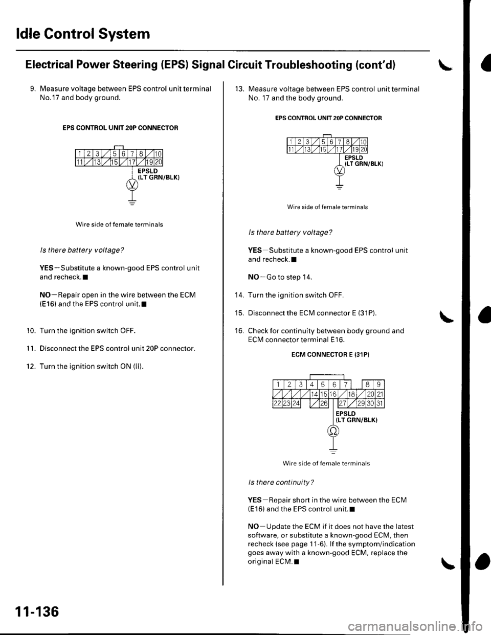
9. Measure voltage between EPS control unitterminal
No.l7 and body ground.
EPS CONTROL UNIT 2OP CONNECTOR
Wire side of female terminals
ls there battety voltage?
YES-Substitute a known-good EPS control unit
and recheck.I
NO- Repair open in the wire between the ECM(E 16) and the EPS control unit.l
Turn the ignition switch OFF.
Disconnect the EPS control unit 20P connector.
Turn the ignition switch ON (ll).
10.
I '�I.
12.
11-136
'13. l\4easure voltage between EPS control unitterminal
No. 17 and the body ground.
EPS CONTROL UNIT 2OP CONNECTOR
Wire side of female terminals
ls there battery voltage?
YES Substitute a known-good EPS control unit
and recheck.l
NO-Go to step 14,
Turn the ignition switch OFF.
Disconnectthe ECM connector E {31P).
Check for continuity between body ground and
ECI\4 connector terminal E16.
ECM CONNECTOR E {31PI
14.
t5_
16.
12345617l 189
56./182A21
2223zi ./29 30ol
EPSLD{LT GRN/BLK)
a,
Wire side ot Iemale terminals
lsthere continuity?
YES Repair short in the wire between the ECN4(E 16) and the EPS control unit.l
NO Update the ECM if it does not have the latest
software, or substitute a known-good ECM, then
recheck (see page 11-6). lf the symptom/indicationgoes away with a known-good ECM, replace the
original ECM.I
Page 493 of 1139
Steering
Steering
Special Tools ............. 17-2
Comoonent Location Index ......................................... 17-3
Steering Wheel Rotational Play Check .....................". 17-4
Power Assist Check .................. .......... 17-4
Steering Linkage and Gearbox Inspection ................. 17-5
Steering Wheel Removal .........................,................... 17-6
Steering Wheel Disassembly/Reassembly ................ 17-7
Steering Wheel Installation ............... 17-8
Steering Column Removal and Installation ...........'... 17-9
Steering Column Inspection .............. 17-11
Steering Lock Replacement .......................................'. 17-'12
Rack Guide Adiustment ....."........'..'.. 17-13
Electrical Power Steering (EPS)17-15
Page 494 of 1139
Steering
SpecialTools(
Ref.No.Tool NumberDescriptionOtyo07MAA-S100200Locknul Wrench. 43 mm
E-.tt)----<,/L\2 r
.V-
6Y
o
I
17-2
Page 495 of 1139
Component Location Index
DRIVER'S AIRBAGASSEMBLYRemoval/lnstallation,page 23-113
STEERING WHEELRemoval, page 17-6Disassembly/Reassembly,page 17 -7Installation, page 17-8
STEERING COLUMNSteering Column Removal and Installation,page 17'9Steering Column Inspection,page 17-1'lSteering Lock Replacement,page 11-12
STEERING GEARBOXRack Guide Adjustment, page '17-13
17-3
Page 496 of 1139

Steering
Steering Wheel Rotational Play
Check
1. Turn the front wheels to the straight ahead position.
2. Measure how far you can turn the steering wheel
left and right without moving the front wheels.
. lf the play is within the limit, the gearbox and
linkage are OK.. lf the playexceedsthe limit, adjustthe rack guide
{see page '17-13). lf the play is still excessive after
rack guide adjustment, inspect the steering
linkage and gearbox {see page 17-5).
BOTATIONAL PLAY: 0 10 mm (0-0.39 in.l
+:
17-4
Power Assist Check
Start the engine, and let it idle.
Attach a commercially available spring scale to the
steering wheel. With the engine idling and the
vehicle on a clean, dry floor, pull the scale as
shown, and read it as soon as the tires begin to turn.
\
1.
3. lf the scale reads no morethan 29 N (3.0 kgf,6.6 lbf),
the power assist is OK. lf it reads more, check these
items:
. Front tire pressure. Steering linkage (see page 17-5). Rack gulde adjustment (see page 17-13). EPS system (see page 17-18)
Page 497 of 1139
I
Steering Linkage and Gearbox Inspection
Check for looseness,and binding.
TIE.ROD LOCKNUTSCheck for looseness.
BOOTInspect Ior damage and deterioration.
12 mm BOLTSInspect for looseness.
STEERING COLUMNInspect for loose columnmounting hardware
STEERING GEARBOXInspect for loose mounting hardware.GEARBOX MOUNTING CUSHIONSInspect for deterioration.
STEERING JOINTSCheck for loose ioint bolts,and loose or binding ioints.
TIE.ROD ENO BALL JOINTlnsoect tor looseness,binding, and damage.
BALLJOINT BOOTInspect for damage and deterioration.
17-5
Page 498 of 1139

Steering
Steering Wheel Removal
SRS components are located in this area. Review the
SRS component locations (see page 23-13), and
precautions and procedures (see page 23-14) in the SRS
section before performing repairs or service.
1. Align the front wheels straight ahead, then remove
the driver's airbag from the steering wheel (see
page 23-113).
2. Disconnect the cruise control sevresume switch
connector (A), and loosen the steering wheel nut
{B).
i
17-6
3. Install a commercially available steering wheel
puller {A) on the steering wheel (B). Free the
steering wheel from the steering column shaft by
turning the pressure bolt (C) ofthe puller.
Note these items when removing the steering
wheel:. Do not tap on the steering wheel orthesteering
column shaft when removing the steering wheel.. lf you thread the puller bolts (D) intothewheel
hub more than 5 threads, the bolts will hit the
cable reel and damage it. To prevent this, install
a pair of jam nuts 5 threads up on each puller bolt.
D
Bemove the steering wheel puller, then remove the
steering wheel nut and steering wheel from the
sleerino column.
{