2002 HONDA CIVIC service indicator
[x] Cancel search: service indicatorPage 433 of 1139

Mainshaft Assembly Clearance Inspection
NOTE: lf replacement is required, always replace the
synchro sleeve and hub as a set.
1. Support the bearing inner race with an appropriate
sized socket (A). and push down on the mainshaft(B).
Measure the clearance bet\iveen 2nd (C) and 3rd (D)
gears with a feeler gauge {E).
. lf the clearance is more than the service limit. go
to step 3.. lf the clearance is within the service limit, go to
step 4.
Standard:0.06 0.16 mm
{0.002 0.006 in.l
Service Limit: 0.25 mm (0.010 in.l
Measure the thickness of 3rd gear.
. lf thethickness of 3rd gearis lessthanthe service
limit, replace 3rd gearwith a new one.. lf thethickness of 3rd geariswithintheservice
limit, replace the 3rd/4th synchro hub with a new
one.
Standard: 23.92-23.97 mm(0.941 0.944 in.)
Service Limit: 23.80 mm (0.937 in.)
4. Measure the clearance between 4th gear (A) and
the distance collar (B) with a dial indicator (C).
. lf the clearance is more than the service limit, go
to step 5.. lf the clearance is within the service limit, go to
step 7.
Standard: 0.06 0.16 mnl(0.002 0.006 in.)
Service Limit: 0.25 mm {0.010 in.)
Measure distance O on the distance co[ar.
. lf distance't is notwithin the standard, replace
the distance collar with a new one.. lf distance e is within the standard, go to step 6.
Standard:24.03 24.08 mm
{0.946-0.9/u in.}
(cont'd)
13-23
Page 434 of 1139

Manual Transmission
Mainshaft Assembly Clearance Inspection (cont'd)
6. Measure the thlckness of 4th gear.
. lf thethickness of 4th gear is lessthantheservice
limit, replace 4th gear with a new one.. lf thethicknessof 4th geariswithin the service
limit. replace the 3rd/4th synchro hub with a new
one.
Standard: 23.92 23.97 mm
(0.941 0.944 in.)
Service Limit: 23.80 mm (0.937 in.)
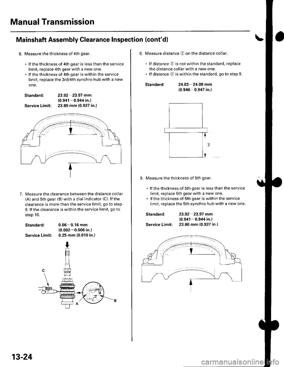
7. l\4easure the clearance between the distance collar
(A) and sth gear (B) with a dial indicator (C). lfthe
clearance is more than the service limit. go to step
8. lf the clearance is with in the service limit, go to
steD 10.
Standard: 0.06 0.16 mm(0.002-0.006 in.)
Service Limit: 0.25 mm (0.010 in.)
13-24
Standard:
Standard:
Service Limit:
8. Measure distance O on the distance collar.
. lf distance O is notwithinthestandard, replace
the distance collar with a new one.' lf distanceO iswithinthe standard, gotostep9.
24.03 24.08 mm
(0.946 0.947 in.)
9. Measure the thickness of 5th gear.
. lf thethicknessof 5th gearis lessthantheservice
limit, replace 5th gear with a new one.. lf the thickness of sth gear iswithin the service
limit. replace the 5th synchro hub with a new one.
23-92 23.97 mm
10.941 0.944 in.l
23.80 mm (0.937 in.l
Page 510 of 1139

How to Troubleshoot EPS DTCs
The troubleshooting flowchart procedures assume that
the cause of the problem is still present and the EPS
indicator is still on, Following the flowchart when the
EPS indicator does not come on can result in incorrect
diagnosis.
The connector iliustrations show the female terminal
connectors with a single outline and the male terminal
connectors with a double outline.
1. Ouestion the customer about the conditions when
the problem occured, and try to reproduce the
same conditions for troubleshooting. Find out
when the EPS indicator came on, such as while
turning. afterturning, when the vehicle was at a
ce rta in speed, etc.
2. When the EPS indicator does not come on during
the test drive, but troubleshooting is done based on
the DTC, check for loose connectors, poor terminal
contact. etc in the affected circuit, before you start
troubleshooting.
3. After trou bleshooting, clear the DTC and test-drive
the vehicle. Be sure the EPS indicator does not
come on.
How to Retrieve EPS DTCs
Honda PGM Tester Method:
1, With the ignition switch OFF, connect the Honda
PGM Tester (A) to the 16P data link connector (DLC)
(B) located under the dash on the driver's side of
the vehicle.
2. Turn the ignition ON (ll), and follow the prompts on
the PGM Tester to display the DTC(s) on the screen.
After determining the DTC, refer to the DTC
Troubleshooting Index.
NOTE: See the Honda PGM Tester user's manual
for specific instructions.
Service Check Signal Circuit Method:
1. With the ignition switch OFF, connect the Honda
PGM Tester (A)to the 16P data link connector (DLC)
(B) located under the dash on the driver's side of
the vehicle.
Short the SCS circuit to body ground using the
Honda PGN4 Tester.
Turn the ignition switch ON {ll).
Record the DTC.
(cont'd)
17-19
Page 512 of 1139

Service Check Signal Circuit Method:
NOTE: Use this procedure when the PGM Tester
software does not match the yearlmodel vehicle you
are working on.
1. With the ignition switch OFF, connect the Honda
PGM Tester (A) to the 16P data link connector {DLC)(B) located under the dash on the driver's side of
the vehicle.
With the vehicle on the ground, set the front wheels
in the straight ahead driving position.
Short the SCS circuit to body ground using the
Honda PGM Tester.
Turn the ignition switch ON (ll). The EPS indicator
comes on for about 6 seconds. Within 4 seconds of
turning the switch ON, while the EPS indicator is on,
turn the steering wheel 45 degrees to the left from
the straight ahead driving position, and hold the
steering wheel in that position until the EPS
indicator goes off.
Within 4 seconds afterthe EPS indicator goes off,
return the steering wheel to the straight ahead
driving position and release the steering wheel.
The EPS indicator comes on again 4 seconds after
releasing the steering wheel,
Within 4 seconds after the EPS indicator comes on,
turn the steering wheel 45 degrees to the left again
and hold it in that position.
The EPS indicator goes off after 4 seconds.
4.
1.Within 4 seconds after the EPS indicator goes off,
return the steering wheel to the straight ahead
driving position again and release the steering
wheel. The EPS indicator blinks twice 4 seconds
after releasing the steering wheel, indicating that
the DTC was erased.
NOTE: If the EPS indicator does not blink twice, an
error was made in the procedure and the DTC was
not erased. Turn the ignition switch OFF, and
repeat the operation from step 3.
Turn the ignition switch OFF afterthe EPS indicator
blinks twice.
9. Disconnect the Honda PGM Tester from the DLC.
10. Perform the DTC code output operation, and be
sure that the code has been erased.
17-21
Page 516 of 1139

EPS Gontrol Unit Inputs and Outputs at Connestor C (20P1
EPS CONTROL UNIT CONNECTOR C (2OP)
Wire side of female terminals
TerminalnumbelWire colorTerminal sign{Terminel name}DescriplionMeasuremeniTerminalsConditions{lqnition switch ON {lll)Voltage
2PNKT/S GND(Torque sensor qround)Ground for the torque
ORNvccl(Voltaqe common 1Power source fortorque3-Groundtartthe enqrneBa$erv voltaqeOV
5YEUBEDVT6(Voltaqe torque 6)Detects torque sensorstonal5 GroundStartthe engine andturn the steerino wheelAbout
YEUBLU(Warninq lamp)Drives the EPS indicatorlidhr6 GroundEPS ONtnotcatol uTl-OVBanerv voltaqe
7BLUAVHTVSP(Vehicle speed pulseiDetects the vehicle speedinput signal for the speedsensor or the ECM (4 pulse/
Raise the vehicle off theground and spin theAlternatingvoltage aboutOV 5V OV-5V
BRNSCS{Servjco check siqnal)Detects service check8-GroundSCS not groundedBattery voltage
10YELIG1llqnition 1Power source for activating10-Groundon switch ON (ll)Batterv voltaqeon switch OFF11G RN//ELvcc2(Voltaqe common 2)Drives the torque sensor1'l-Groundtan the enoineAbout5Von switch OFF8LU/ORNVT3(Voltaoe toroue 3)Detects torque sensor13-GroundStartthe engine andtrrrn the steerino wheelAbout5-0 v
YEUBLKT/SIG(Torque sensor F/SDetects torque sensorsrgnal15-GroundStartthe engineMomentarily 5 V
1'lLT GRN/BI KPSWiPower steerino switch)Provides power steeringswitch sionall7-GroundStartthe engine andnrrn the steerino wheel0-12V
19BLUNEPDetects the engine pulse19-GroundStartthe engine, and let;t idte
20GRYDIAG-HCommunications withHonda PGNI Tester20-GroundPGM Tester not5V
17-25
Page 626 of 1139

ABS Components
General Troubleshooting Information (cont'd)
How to Troubleshoot ABS DTCs
The troubleshooting flowchart procedures assume that
the cause of the oroblem is still Dresent and the ABS
indicator is still on. Following the flowchart when the
ABS indicator does not come on can result in incorrect
diagnosis.
The connector illustrations show the female terminal
connectors with a single outline and the male terminal
connectors with a double outline.
1. Ouestion the customer about the conditions when
the problem occured, and try to reproduce the
same conditions for troubleshooting. Find out
when the ABS indicator came on, such as during
ABS control, after ABS control, when the vehicle
was at a certain speed, etc.
2. When the ABS indicator does not come on during
the test-drive, but troubleshooting is done based on
the DTC, check for loose connectors. poor terminal
contact, etc., before you start troubleshooting.
3. After troubleshooting, clear the DTC,disconnect the
Honda PGM Tester. and test-drive the vehicle.
Make sure the ABS indicator does not come on.
How to Retrieve ABS DTCs
Honda PGM Tester Method:
1, Wjth the ignition switch OFF, connect the Honda
PGM Tester (A) to the 16P data link connector (DLC)
(B) under the driver's side of the dashboard.
19-32
2. Turn the ignition switch ON (ll), and follow the
prompts on the PGM Tester to display the DTC{S)
on the screen. After determining the DTC, refer to
the DTC Troubleshooting Index.
NOTE: See the Honda PGM Tester user's manual
for specific instructions.
Service Check Signal (SCS) Circuit Method:
1. With the ignition switch OFF, connect the Honda
PGM Tester (A) to the 16P data link connector (DLC)
(BI under the driver's side of the dashboard.
2. Short the SCS circuit to body ground using the
Honda PGM Tester.
3. Turn the ignition switch ON (ll).
Page 1033 of 1139

sRs
General Troubleshooting Information (cont'dl
Erasing the DTG Memory
Specisl Tool Required
SCS service connector 07PAz-0010100
To erase the DTC(S)from the SRS unit, use a Honda
PGM Tester {see lhe Honda PGfM Tester SRS Vehicle
System Supplement) or the following procedure.
1. Make sure the ignition switch is OFF.
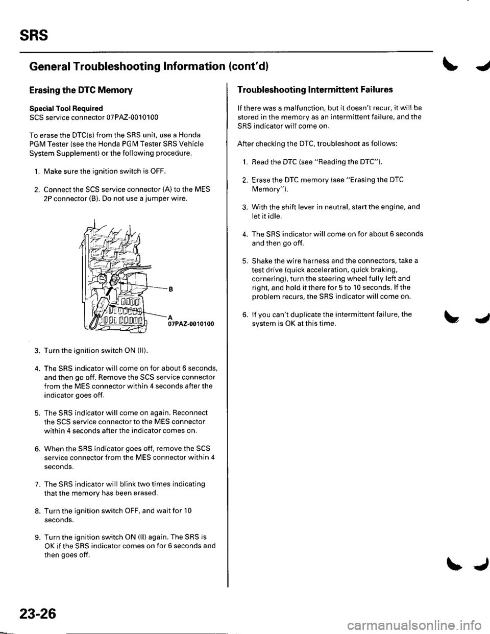
2. Connect the SCS service connector {A) to the MES
2P connector (B). Do not use a jumper wire.
07PAZ-0010100
3. Turn the ignition switch ON (ll).
4. The SRS indicator will come on for about 6 seconds,
and then go off. Remove the SCS service connector
from the MES connector within 4 seconds after the
indicator goes off.
5. The SRS indicator will come on again. Reconnect
the SCS service connector to the MES connector
within 4 seconds after the indicator comes on.
6. When the SRS indicator goes off, remove the SCS
service connector from the MES connector within 4
seconds.
7. The SRS indicator will bllnk two times indicating
that the memory has been erased.
8. Turn the ignition switch OFF, and wait for '10
seconds.
9. Turn the ignition switch ON (ll) again. The SRS js
OK if the SRS indicator comes on for 6 seconds and
then goes off.
23-26
\J
Troubleshooting lntermittent Failures
lf there was a malfunction, but it doesn't recur. it will be
stored in the memory as an intermittent failure, and the
SRS indicator will come on.
After checking the DTC, troubleshoot as follows:
1. Read the DTC (see "Reading the DTC").
2. Erase the DTC memory (see "Erasing the DTC
Memory").
3. With the shift lever in neutral, start the engine, and
let it idle.
The SRS indicator will come on for about 6 seconds
and then go off.
Shake the wire harness and the connectors. take a
test drive (quick acceleration, quick braking,
cornering), turn the steering wheel fully left and
right, and hold it there for 5 to '10 seconds. lf the
problem recurs, the SRS indicator will come on.
lf you can't duplicate the intermittent failure, the
system is OK at this time.
4.
Page 1034 of 1139

I
Initializing the OPDS {Occupant Position Detection System} Unit
Special Tool Required
SCS service connector 07PAz-00'1 01 00
When a seat-back cover, seat-back cushion, and/or OPDS unit is replaced, initialize the OPDS by following theprocedure below.
NOTE: Make sure the front passenger's seat is dry. Set the seat-back in the normal position, and make sure there isnothing on the seat.
'1. l\4ake sure the ignition switch is OFF.
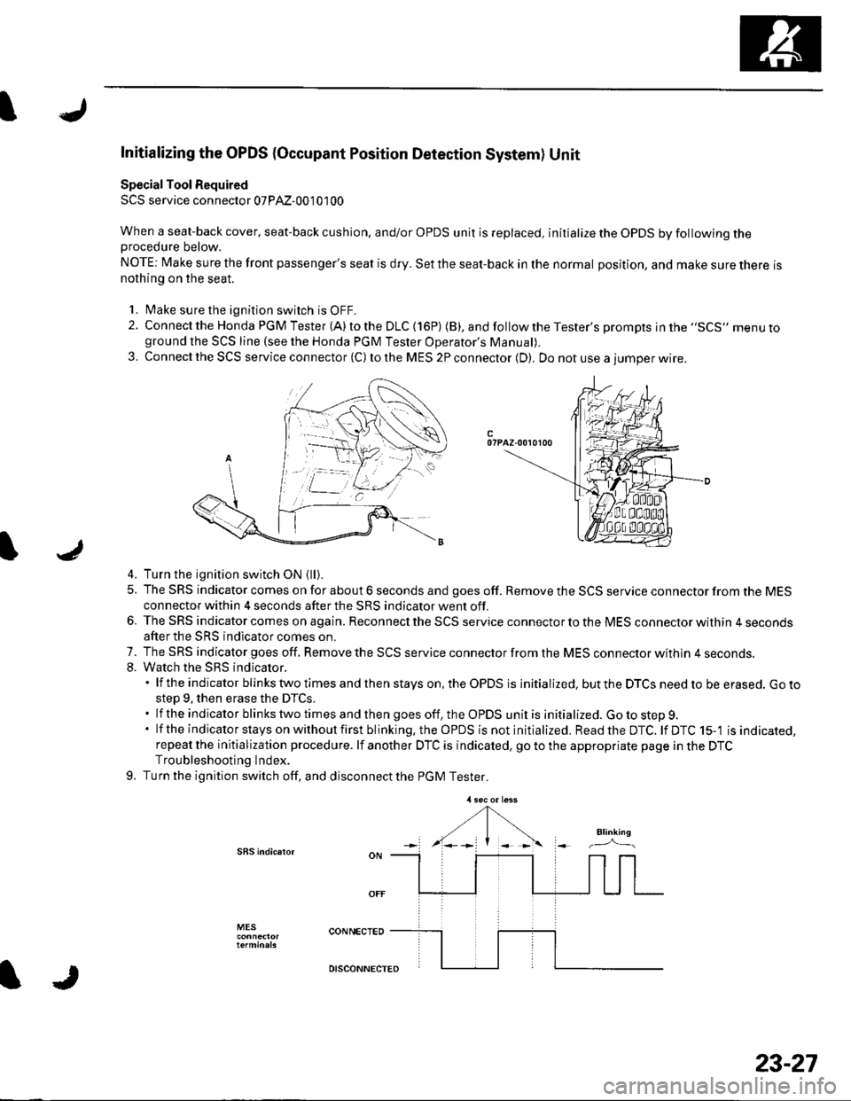
2. Connect the Honda PGM Tester (A) to the DLC (16P) (B), andfollowtheTester's prompts jn the ,,SCS,, menu toground the SCS line (see the Honda PGM Tester Operator's ManuaD.
3. Connect the SCS service connector (C) to the MES 2P connector (D). Do not use a iumoer wire.
c07PAZ-00r0100
4. Turn the ignition switch ON {ll).
5. The SRS indicator comes on for about 6 seconds and goes off. Remove the SCS service connector from the MESconnector within 4 seconds after the SRS indicator went off.
6. The SRS indicator comes on again. Reconnect the SCS service connector to the MES connector within 4 secondsafter the SRS indicator comes on.
7. The SRS indicator goes off. Remove the SCS service connector from the MES connector withln 4 seconds.8. Watch the sRS indicator.'lftheindicatorblinkstwotimesandthenstayson,theOPDSisinitialized.buttheDTCSneedtobeerased.Goto
step 9, then erase the DTCS..lftheindicatorblinkstwotimesandthengoesoff,theOPDSunitisinitialized.Gotostep9.
' lf the indicator stays on without first blinking.the OPDS is not initialized. Readthe DTC. lf DTC 15-'l is indicated,repeat the initialization procedure. lf another DTC is indicated, go to the appropriate page in the DTCTroubleshooting Index.
9. Turn the ignition switch off, and disconnect the PGM Tester.
SBS indic.ror
MES
IJ
DISCONNECTED
23-27