Page 832 of 1139

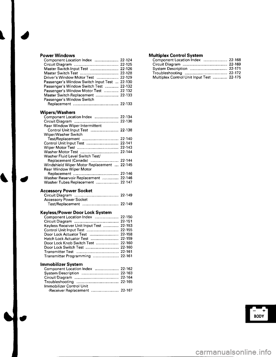
Power WindowsComponent Location Index ..........
circuit Diagram . .. ............... .........:.::::.::::.:Master Switch Input Test ...........................Master Switch TestDriver's Window Motor Test .....................
Passenger's Window Switch lnput Test ...Passenger's Window Switch Test .............
Passenger's Window Motor Test ..............
lMaster Switch Replacement ......................
Passenger's Window SwitchReplacement
Wipers/WashersComponent Location Index .......................
Circuit DiagramRear Window Wiper Intermiftent
Control Unit Input Test ...........................Wiper/Washer SwitchTesVReplacementControl Unit Input Test ...............................Wiper Motor Test
Washer Motor TestWasher Fluid Level Switch TesV
Replacement (Canadal ..........................
Windshield Wiper Motor Replacement ....
Rear Window Wiper MotorReplacementWasher Reservoir Replacement ................
Washer Tubes Beplacement ......................
Accessory Power SocketCircuit Diagram ......... 22-149
Accessory Power Socket
TesVReplacement ................................... 22-1 49
Keyless/Power Door Lock System
Component Location Index ....................... 22-150
Circuit Diagram ......... 22-151Keyless Receiver Unit InputTest ............... 22-153
Control Unit Input Test ............................... 22-155
Door LockActuatorTest .........,.......,..,.,..... 22-158Hatch LockActuatorTest ........................... 22-159
Door Lock Knob Switch Test ...................... 22-160
Door Lock Switch Test ................................ 22-160
Transmitter Test ....... 22-161
Transmitter Programming ......................... 22-161
Multiplex Control SystemComponent Location Index ...........
circuit Diagram ...... ........................::.:..:.::.:
Svstem DescriDtionTroubleshootingMultiolex Control Unit InDut Test .............
22 12422-12522-12622-12822-129
22- t30
22-13222 13222-133
22-133
22-134
22-138
22-14022-14122-14322-144
22-14422-145
22-14622-14622 147
22,16422-16922-17'l22,11222-175
lmmobilizer Systemcomponent Location Index ...........
System Description ....... ............. ..:..:..:.:...
Circuit DiagramTroubleshootinglmmobilizer Control Unit-Receiver Replacement ...........................
22-16222-16322-164
22-167
Page 843 of 1139
Relay and Control Unit Locations
Door and Seat
Driver's Door:
Passenger's Seat:
l\:
].\
POWER WINDOW MASTER SWITCHlHas built-in control unit)
22-12
Page 871 of 1139
Connectors and Harnesses
\,Connector to Harness lndex (cont'd)
Driver's Door Wire Harness
Connector or TerminalReICavitiesLocationConnectstoNotesDriver's door lock actuatorDriver's door lock knob switchDriver's door lock switchDriver's door speakerDriver's power window motorLeft power mirror actuatorLeft tlveeterPower window master switchc504
c505
9101723
85
6
2332
62
20
't3
Driver's doorDriver's doorDriver's doorDriver's dooaDriver's doorDriver's doorDriver's doorDriver's doorUnder left side of dash
Under left side of dash
Dashboard wire harness A\see page 22-261Dashboard wire harness A
DRIVER'S OOOR WIRE HABNESS
22-40
Page 879 of 1139

Ground Distribution
Ground to Components Index
GroundComponent or circuit qrounded
Batterv, Transmission housinq
E ngine
G 101ECM (PG is BLK; LG is BRN/YEL)
BLK: IAC valve, lgnition coils, Vehicle speed sensor, VTEC solenoid valve
BRNA/EL: Camshaft oosition (CMP) sensor. CKP sensor, TDC sensor. VTEC oil pressure switch
G 15'�]EPS control unit
G201ELD unit. Multiplex control inspection connector, Multiplex control unit, Power window relay, Rear
window washer motor, Right front parking light, Right front side marker light, Right front turn signal
light, Turn signal/hazard relay, Washer fluid level sensor (Canada) , Windshield washer motor,
Windshield wiDer motor
G202ABS modulator-control unit
G301
G401
Blower motor relay, Brake fluid level switch, Condensor fan motor, Cruise control actuator, Left front
parking light, Left front side marker light, Left front turn signal light, Radiator fan motor, Radiator fan
swrtcn
Combination liqht switch, lqnitlon kev srvitch, Wiper/wasfrer sr,virch
G402Left and riqht airbaq sensors, SRS unit
G 451Data link connector (DLC)
G501Clutch interlock switchm Clutch pedal position switch (for cruise control), Cruise control main switch,
Cruise control unit, Daytime running lights control unit (Canada), Driver's door lock knob switch,
Driver's door lock switch, Driver's power window motor, Heater control panel, Left power mirror
defogger (Canada), left side turn signal light, Moonroof control unit, Monroof open and close relays,
Moonroof position sensor '1, Moonroof seitch, Power mirror switch, Power transistor, Power window
master switch. SDotliqhts
G502Accessory power socket, Gauge assembly, Keyless receiver unit, lvlultiplex control unit, Right power
mirror defogger {Canada)
G503Audio unit
G551Driver's seat belt switch, Fuel gauge sending unit, Fuel pump, Memory erase signal (IMES) connector,
OPDS unit. Rioht seat belt switch
G552High mount brake light, License plate lights, Rear window defogger, Rear window defogger noise
condenser. Rear window wioer motor, Hatch latch switch
Back-up lights, Brake lights, Rear side marker lights, Rear turn signal lights, Rear window wiper noise
condenser, Rear window wiper intermittent control unit, Taillights
22-48
Page 957 of 1139
Power Windows
Master Switch Input Test
NOTE: The power window control unit is built into the power window master switch, and it only controls the driver'swindow operations.
1. Remove the window master switch {A) (see page 22-133).
2. Disconnect the 14P connector (B) from the master switch.
GRN/WHT
3. Inspect the co nnector and socket terminals to be sure they are all making good contact.
. lf theterminals are bent, loose orcorroded, repairthem as necessary, and recheckthe system.. lf the terminals look OK, go to step 4.
22-126
Page 958 of 1139

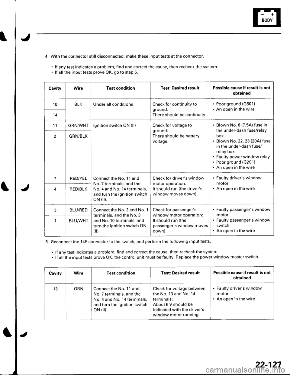
4. Withthe connector still disconnected, makethese inputtests attheconnector.
.lfanytestindicatesaproblem,findandcorrectthecause.thenrecheckthesystem.
. lf allthe inputtests prove OK, goto step 5.
5. Reconnect the 14P connector to the switch, and perform the following input tests.
.lfanytestindicatesaproblem,findandcorrectthecause,thenrecheckthesystem.
. lf all the input tests prove OK, the control unit must be faulty. Replace the power window master switch.
CavityWireTest conditionTest: Desired resultPossible cause if result is not
obtained
10BLKUnder all conditionsCheck for continuity to
grouno:
There should be continuity.
. Poor ground {G50'1). An open in the wire
14
11G RN^,^/HTlgnition switch ON (ll)Check for voltage to
ground:
There should be battery
voltage.
Blown No.6 (7.5A) fuse in
the under-dash fuse/relay
box
Blown No. 22,23 l2OA) tuse
in the under-dash fuse/
relay Dox
Faulty power window relay
Poor ground (G201)
An open in the wire
2GRN/BLK
1RED/YELConnect the No. 'l'1 and
No. 7 terminals, and the
No, 4 and No. 14 terminals,
and turn the ignition switch
oN flr).
Check for driver's window
molor operaflon:
It should run (the driver's
window moves down).
. Faulty driver's window
motor. An open in the wireRED/B LK
3BLU/REDConnect the No. 2 and No. 1
terminals, and the No. 3
and No. 10 terminals, and
turn the ignition switch ON
fi r),
Check for passenger's
window motor operation:
It should run (the
passenger's window moves
oown).
Faulty passenger's window
motor
Faulty passenger's window
swatch
An open in the wire
BLU/WHT
CavityWireTest conditionTest: Desired resultPossible cause if result is not
obtained
13ORNConnect the No. 11 and
No. 7 terminals, and the
No. 4 and No. 14 terminals,
and turn the ignition switch
oN 0r).
Check for voltage between
the No. 13 and No. 14
termtnals:
About6Vshouldbe
indicated with the driver's
window motor running.
. Faulty driver's window
molor. An open in the wire
22-127
Page 960 of 1139
Driver's Window Motor Test
Motor Test:
Remove the door panel (see page 20-4).
Disconnect the 4P connector (A) from the driver's
window motor.
1.
4.
Test the motor in each direction by connecting
battery power and ground according to the table.
When the motor stops running, disconnect one
lead immediatelv.
Terminal
il;;'-\2
UPeo
DOWN@e
lf the motor does not run or fails to run smoothly,
replace rL
1.
Pulser Test:
Reconnect the 4P connector to the driver's window
motor, and reconnect the 20P connector to the
power window master switch.
Connect the test leads of a voltmeter to the No, 3
and No. 4 terminals of the driver's window motor
4P connector.
Run the motor using the master switch. The
voltmeter should read about 6 V.
lf the voltage is not as specified, check for an open
in the wires. lf the wires are OK, replace the driver's
window motor.
22-129
Page 961 of 1139

Power Windows
1.
2.
Passenger's Window Switch Input Test
Remove the switch panel (see page 20-4).
Disconnect the 5P connector (A) from the switch (B).
o
'' "'"1.
4.
Wire side of female terminals
BLU/WHTGRN/BLK
Input the connector and socket terminals to be sure they are all making good contact.
. lf theterminals are bent, loose or corroded, repairthem as necessary, and recheckthe system.. lf the terminals look OK, go to step 4.
Reconnect the connector, and using a back probe, make these input tests at the connector. lf any test indicates aproblem, find and correct the cause, then recheck the svstem,
CavitvWireTest conditionTest: Desired resultPossible cause if result is not obtained
3GRN/BLKlgnition switch ON
{ ll)
Check for voltage to
grouno:
There should be battery
voltage.
Blown No.6 (7,5A)fuse in the
under-dash fuse/relay box
Blown No.22 {20A)fuse in the
under-dash fuse/relay box
Faulty power window relay
An open in the wire
Poor qround (G201)
2BLD,A/VHTlgnition switch ON( )
At the master
window switch,
press and hold
down the
passenger's switch
Check for voltage to
ground:
There should be battery
voltage.
Faulty master window switch
An open in the wire
BLU/REDlgnition switch ON(||)
At the master
window switch,
pull up and hold
the passenger's
switch
Check for voltage to
grouno:
There should be battery
voltage.
Faulty master window switch
An open in the wire
22-130