2002 HONDA CIVIC power
[x] Cancel search: powerPage 1036 of 1139
IJ
lr
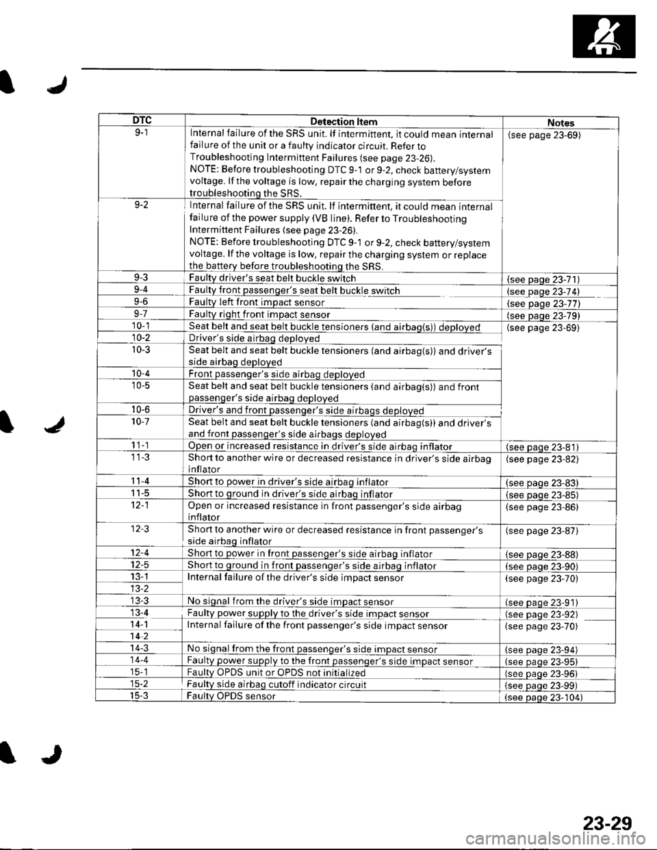
DTCDetection ltemNotes9-1Internal failure of the SRS unit. lf intermittent, it could mean internalfailure of the unit or a faulty indicator circuit. Refer toTroubleshooting Intermittent Failures (see page 23-26).
NOTE: Before troubleshooting DTC 9-1 or 9-2, check battery/systemvoltage. lf the voltage is low, repair the charging system beforetroubleshooting the SRS.
(see page 23-69)
9-2Internal failure of the SRS unit. lf intermittent, it could mean internalfailu re of the power supply (VB line). Refer to TroubleshootingIntermittent Failures (see page 23-26).
NOTE: Before troubleshooting DTC 9-1 or 9-2, check battery/systemvoltage. lf the voltage is low, repair the charging system or replacethe b€ttery before troubleshooting the SRS.
9-3Faulty driver's seat belt buckle switch(see Daqe 23-71)9-4
9-6
FaultLtglt passenger's seat belt buckle switch
Faulty Ieft front imDact sensorlgqgfage 23-74)
{see Daqe 23-77)9-7Faulty right front impact sensor(see paqe 23-79)10-1Seat belt and seat belt buckle tensioners (and airbag(s)) deployedDriver's side airbag deployed
Seat belt and seat belt buckle tensioners (and airbag(s)) and driver'sside airbag deployed
Front passenqer's side airbao deDloved
(see page 23-69)10-2
r0-3
'10-4
'10-5Seat belt and seat belt buckle tensioners (and airbag(s)) and frontpassenqer's side airbaq deDloved
10-6Driver's and front passenqer's side al10-7Seat belt and seat belt buckle tensioners (and airbag(s)) and driver'sand front passenger's side airbags deployed
1 1-1Open or increased resistance in driver's side airbao inflator(see paqe 23-81)Short to another wire or decreased resistance in driver's side airbaoinflator
(see page 23-82)
11-4Short to power in driver's side airbaq inflator(see oaqe 23-83)I t-5Short to ground in driver's side airbaq inflator{see paqe 23-85)Open or increased resistance in front passenger's side airbaginflator
(see page 23-86)
Short to another wire or decreased resistance in front passenger's
side airbag inflator
(see page 23-87)
12-4Short to power in front passenqer's side airbaq inflator{see Daqe zJ-uu}I z-5Short to ground in front passenger's side airbaq inflator(see oaqe 23-90)13-1Internal failure of the driver's side impact sensor(see page 23-70)
No signal from the driver's side impact sensor(see paqe 23-91)13-4
14-1-7ii,
Faulty power supply to the df,rglllug t Opact s9I99LInternal failure ofthe front passenger's side impact sensor
(see page 23-92)(see page 23-70)
14-3No signal from the front passenger's side impact sensor(see paqe 23-94)14-4Faulty power supply to the front passenqer's side impact sensor(see page 23-95)15-1Faultv OPDS unit or OPDS not initialized(see paqe 23-96115-2Faulty side airbag cutoff indicator circuit(see Daqe 23-99)15-3Faulty OPDS sensor(see oaoe 23-104)
IJ
23-29
Page 1039 of 1139
sRs
System Description (cont'dl
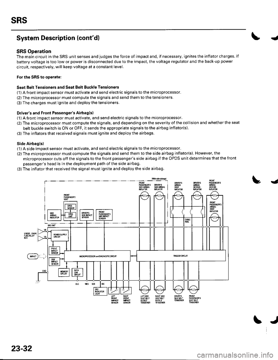
SRS Operation
The main circuit in the SRS unit senses and judges the force of impact and, if necessary. ignites the inflator charges. lf
battery voltage is too low or power is disconnected due to the impact, the voltage regulator and the back-up power
circuit, respectively, will keep voltage at a constant level.
For the SRS to operate:
Seat Belt Tensioners and Seat Belt Buckle Tensioners
(1) A front impact sensor must activate and send electric signals to the microprocessor.
(2) The microprocessor must compute the signals and send them to the tensioners.
(3) The charges must ignite and deploy the tensioners.
Driver's and Front Passenger's Airbagls)
(1) A front impact sensor musl activate. and send electric signals to the microprocessor.
(2) The microprocessor must compute the signals. and depending on the severity of the collision and whether the seat
belt buckle swilch is ON or OFF, it sends the appropriate signals to the airbag inflator(s).
(3) The inflators that received signals must ignite and deploy the airbags.
Side Airbaglsl( 1) A side impact sensor must activate, and send electric signals to the microprocessor.
(2) The microprocessor must compute the signals and send them to the side airbag inflator(s). However, the
microprocessor cuts off the signals to the front passenger's side airbag if the OPDS unit determines that the tront
passenger's head is in the deployment path of the side airbag.
(3) The inflator that received the signal must ignite and deploy the side airbag.
lw$ad..n sl
!J
T'sEcttoJn0mP gsfrlctR S oXrVEr S I9oEAiA$ SOtlr&G I
f'**)r !
23-32
\J
Page 1046 of 1139
s
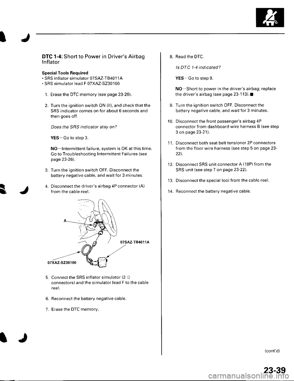
DTC 1-4: Short to Power in Driver's Airbag
Inflator
SpecialTools Bequired. sRS inflator simulator 07SAZ-T84011A. SRS simulator lead F 07XAZ-S230100
1. Erase the DTC memory (see page 23-26).
2. Turn the ignition switch ON (ll), and check that the
SRS indicator comes on for about 6 seconds and
then goes off.
Does the SRS indicator stay on?
YES Go to step 3.
NO Intermittent failure, system is OK at this time.
Go to Troubleshooting Intermittent Failures (see
page 23-26).
3. Turn the ignition switch OFF. Disconnect the
battery negative cable, and wait for 3 minutes.
4. Disconnect the driver's airbag 4P connector (A)
from the cable reel.
07sAz-T84011A
Connect the SRS inflator simulator (2 0
connectors) and the simulator lead F to the cable
reel.
Reconnect the battery negative cable.
Erase the DTC memory.
6.
1.
9.
10.
't 4.
11.
12.
Read the DTC.
ls DTC 1-4 indicated?
YES-Go to step 9.
NO-Short to power in the driver's airbag; replace
the driver's airbag (see page 23-1 13).1
Turn the ignition switch OFF. Disconnect the
battery negative cable, and wait for 3 minutes.
Disconnect the front passenger's airbag 4P
connector from dashboard wire harness B (see step
3 on page 23'21).
Disconnect both seat belt tensioner 2P connectors
from the floor wire harness (see step 5 on page 23-
221.
Disconnect SRS unit connector A (18P)from the
SRS unit (see step 7 on page 23-22).
Disconnect the special tool from the cable reel.
Reconnect the battery negative cable.
(cont'd)
23-39
Page 1052 of 1139
I
I
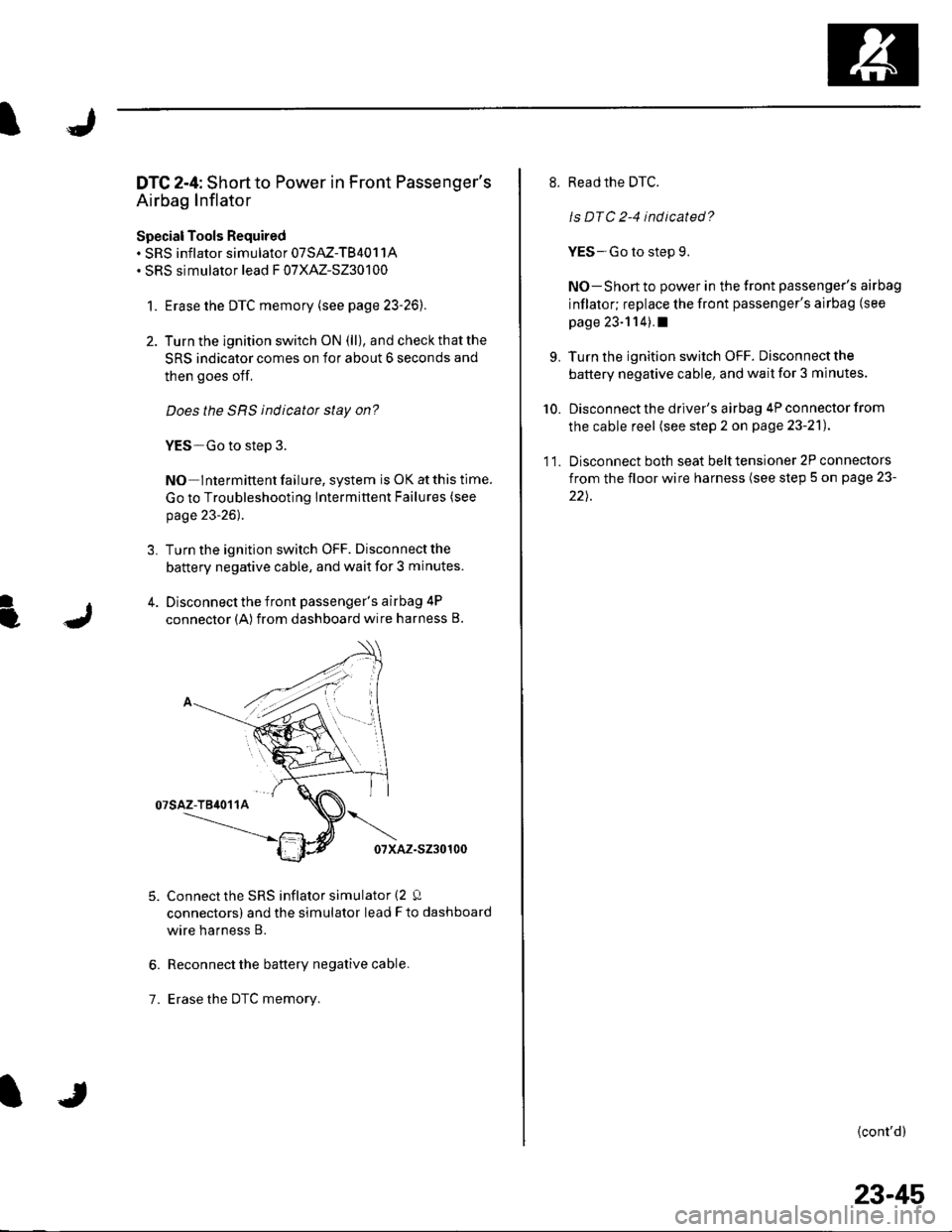
DTC 2-4: Shortto Power in Front Passenger's
Airbag Inflator
Special Tools Required. SRS inflator simulator 07SAZ-TB4011A. SRS simulator lead F 07XAZ-S230100
1. Erase the DTC memory (see page 23-26).
2. Turn the ignition switch ON (ll), and check that the
SRS indicator comes on for about 6 seconds and
then goes off,
Does the SRS indicatot stay on?
YES-Go to step 3.
NO Intermittent failure, system is OK at this time.
Go to Troubleshooting lntermittent Failures (see
page 23-26).
3. Turn the ignition switch OFF. Disconnectthe
battery negative cable, and wait for 3 minutes.
4. Disconnect the front passenger's airbag 4P
connector (A) from dashboard wire harness B.
07sAz-T84011A
07xAz-s230100
Connect the SRS inflator simulator (2 Q
connectors) and the simulator lead F to dashboard
wire harness B.
Reconnect the battery negative cable.
Erase the DTc memory.
6.
7.
8. Read the DTC.
ls DTC 2-4 indicated?
YES-Go to step 9.
NO-Short to power in the front passenger's airbag
inflator; replace the front passenger's airbag (see
page 23-114).I
9. Turn the ignition switch OFF. Disconnectthe
battery negative cable, and wait for 3 minutes.
10. Disconnect the driver's airbag 4P connector from
the cable reel (see step 2 on page 23-21).
11. Disconnect both seat belttensioner 2P connectors
from the floor wire harness (see step 5 on page 23-
22).
{cont'd)
23-45
Page 1053 of 1139
sRs
13.
14.
DTC Troubleshooting (cont'd)
Disconnect SRS unit connector A (18P) from the
SRS unit (see step 7 on page 23-221.
Disconnect the special tool from dashboard wire
harness B.
Reconnect the battery negative cable.
Turn the ignition switch ON (ll).
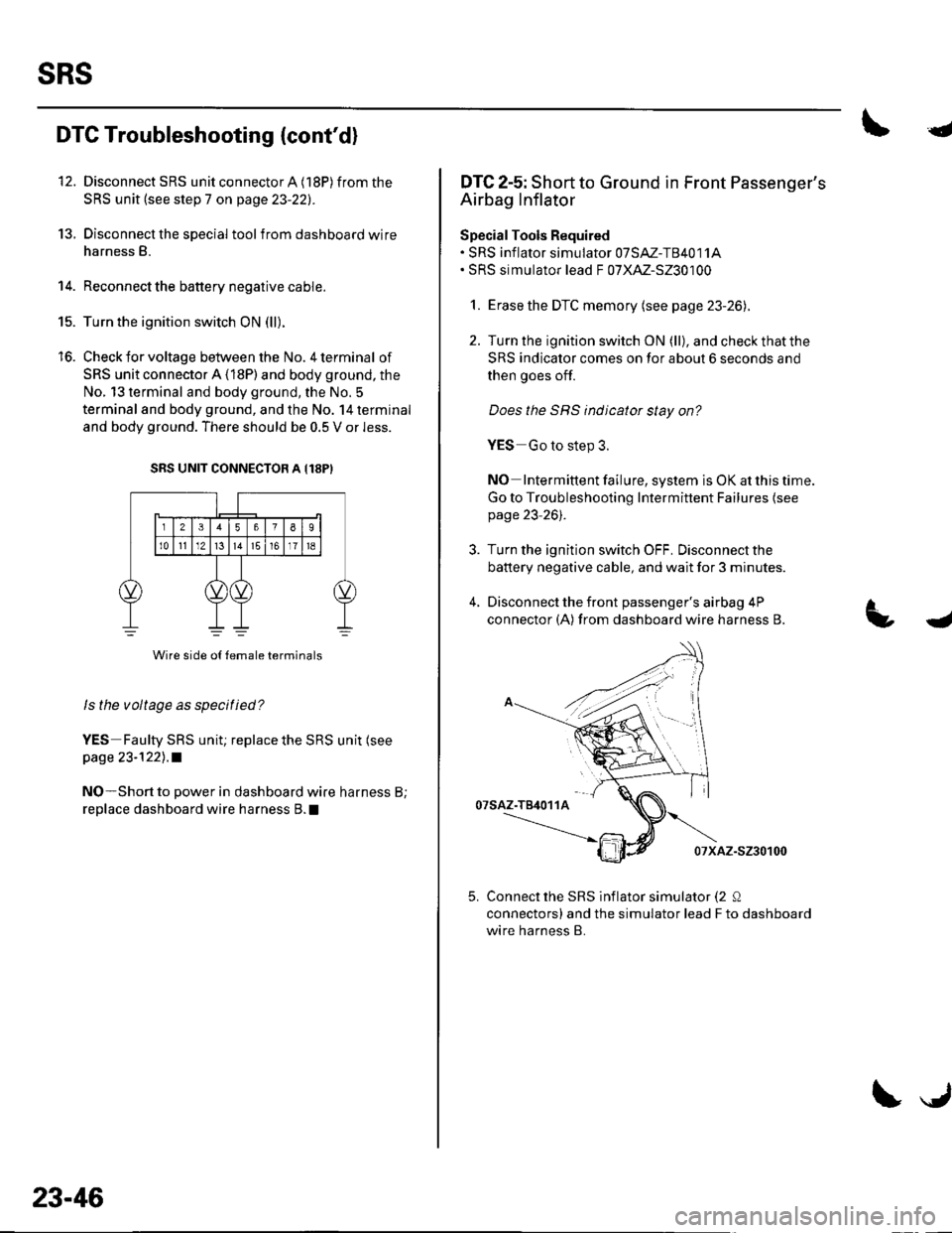
Check for voltage between the No. 4 terminal of
SRS unit connector A (18P) and body ground, the
No. 13 terminal and body ground, the No. 5
terminal and body ground, and the No. 14 terminal
and body ground. There should be 0.5 V or less.
SRS UNIT CONNECTOB A {18PI
Wire side o{ {emale terminals
ls the voltage as specified?
YES Faulty SRS uniu replace the SRS unit (see
page 23-1221 .a
NO-Short to power in dashboard wire harness B;
replace dashboard wire harness B. !
15.
to.
23-46
\J
{
DTC 2-5: Short to Ground in Front Passenger's
Airbag Inflator
SpecialTools Required. SRS inf lator simulator 07SAZ-T84011A. SRS simulator lead F 07XAZ-S230100
1. Erase the DTC memory (see page 23-26).
2. Turn the ignition switch ON (ll), and check that the
SRS indicator comes on for about 6 seconds and
then goes off.
Does the SRS indicator stay on?
YES Go to step 3.
NO Intermittent failure, system is OK at this time.
Go to Troubleshooting Intermittent Failures {seepage 23-261.
3. Turn the ignition switch OFF. Disconnectthe
battery negative cable, and wait for 3 minutes.
4, Disconnect the front passenger's airbag 4P
connector (A) from dashboard wire harness B.
07saz-T84011A
07xAz-s230100
Connect the SRS inflator simulator (2 Q
connectors) and the simulator lead F to dashboard
wire harness B.
4
5.
Page 1058 of 1139
![HONDA CIVIC 2002 7.G Workshop Manual IJ
L
]
DTC 3-4: Short to Power in Drivers Seat Belt
Tensioner
SpecialTools Bequired. SRS lnflator simulator 07SAZ-TB4011A. SRS simulator lead C 07TM-S25011A. SRS simulator lead F 07XAZ-S230100
1. Era HONDA CIVIC 2002 7.G Workshop Manual IJ
L
]
DTC 3-4: Short to Power in Drivers Seat Belt
Tensioner
SpecialTools Bequired. SRS lnflator simulator 07SAZ-TB4011A. SRS simulator lead C 07TM-S25011A. SRS simulator lead F 07XAZ-S230100
1. Era](/manual-img/13/5744/w960_5744-1057.png)
IJ
L
]
DTC 3-4: Short to Power in Driver's Seat Belt
Tensioner
SpecialTools Bequired. SRS lnflator simulator 07SAZ-TB4011A. SRS simulator lead C 07TM-S25011A. SRS simulator lead F 07XAZ-S230100
1. Erase the DTC memory (see page 23-261.
2. Turn the ignition switch ON (ll), and check that the
SRS indicator comes on for about 6 seconds and
then goes off.
Does the SRS indicatot stay on?
YES - Go to step 3.
NO Intermittent failure, system is OK at this time.
Go to Troubleshooting Intermittent Failures (see
page 23-261.
Turn the ignition switch OFF. Disconnect the
battery negative cable, and wait for 3 minutes.
Disconnect the driver's seat belt tensioner 2P
connector (A) from the floorwire harness.
07sAz-T84011A
5. Connect the SRS inflator simulator (2 !J connector)
and simulator lead C to the floor wire harness.
I
6. Reconnect the battery negative cable.
7. Erase the DTC memory.
8. Read the DTC.
Is DTC 3-4 indicated?
YES - Go to step 9.
NO-Short to power in the driver's seat belt
tensioner; replace the driver's seat belt
(see page 23-4).1
L Turn the ignition switch OFF. Disconnect the
battery negative cable, and wait for 3 minutes.
10. Disconnect floor wire harness 4P connector C403
(A) from dashboard wire harness B.
TB4O11A
Connect the SRS inflator simulator (2 0
connectors) and simlator lead F to dashboard wire
harness B.
Reconnect the battery negative cable.
Erase the DTC memory.
Read the DTC.
ls DTC 3-4 indicated?
YES -- Go to step 15.
NO-Shon to power in the floor wire harness;
replace the floor wire harness.I
Turn the ignition switch OFF. Disconnect the
battery negative cable, and wait for 3 minutes.
11.
't2.
14.
(cont'd)
23-51
Page 1059 of 1139
sRs
DTC Troubleshooting (cont'dl
16. Disconnecl the driver's airbag connector (see step
2 on page 23-21l,Iront passenger's airbag
connector (see step 3 on page 23-2'l), and front
passenger's seat belt tensioner connector (see step
5 on page 23-221 .
17. Disconnect SRS unit connector A (l8P)from the
SRS unit (see step 7 on page 23-22).
18. Disconnect the specialtool from dashboard wire
harness B.
19. Reconnect the battery negative cable.
20. Turn the ignition switch ON (ll),
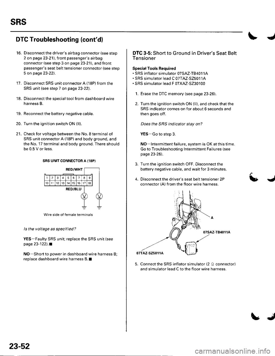
21. Check for voltage between the No. 8 terminal of
SRS unit connector A (18P) and body ground, and
the No. 17 terminal and body ground. There should
be 0.5 V or less.
SRS UNIT CONNECTOR A {18PI
ls the voltage as specified?
YES-Faulty SRS unit; replace the SRS unit {seepage 23-122], .a
NO Shortto power in dashboard wire harness B;
replace dashboard wire harness B.l
23-52
LJ
DTC 3-5: Short to Ground in Driver's Seat Belt
Tensioner
Special Tools Required. sRS inflalor simularor 07sAz-TB4011A. SRS simulator lead C 07TAZ-S25011A. SRS simulator lead F 07XAZ-S230100
1. Erase the DTC memory {see page 23-26).
2. Turn the ignition switch ON (ll), and check that the
SRS indicator comes on for about 6 seconds and
then goes off.
Does the SRS indicator stay on?
YES Go to step 3.
NO Intermittent failure, system is OK at this time.
Go to Troubleshooting Intermittent Failures (see
page 23-26).
3. Turn the ignition switch OFF. Disconnect the
battery negative cable, and wait for 3 minutes.
4, Disconnect the driver's seat belt tensioner 2P
connector (A) from the floor wire harness,
-T84011A
07TAZ-S25011A
L
5. Connect the SRS inflator simulator (2 Q conneclor)
and simulator lead C to the floor wire harness.
Page 1063 of 1139
sRs
DTC Troubleshootang (cont'dl
DTG 21-4: Short to Power in Driver's Seat Belt
Buckle Tensioner
SpecialTools Required. SRS inflator simulator 07SAZ-TB4011A. SRS simulator lead F 07XM-S230100
1. Erase the DTC memory (see page 23-26).
2. Turn the ignition switch ON (ll), and check that the
SRS indicator comes on for about 6 seconds and
then goes off.
Does the SRS indicatot stay on?
YES-Go to step 3.
NO Interminent failure, system is OK at this time.
Go to Troubleshooting Intermittent Failures (see
page 23'26).
3. Turn lhe ignition switch OFF. Disconnect the
battery negative cable, and wait for 3 minutes.
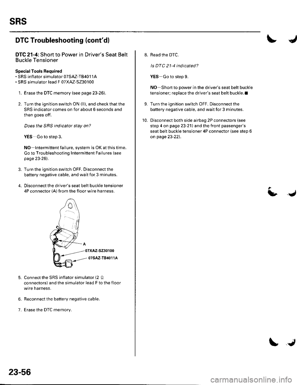
4. Disconnect the driver's seat belt buckle tensioner
4P connector (A) from the floor wrre narness.
Connectthe SRS inflator simulator {2 0
connectors) and the simulator lead F to the f loor
wire harness.
Reconnect the battery negative cable.
Erase the DTC memory.7.
5.
23-56
\, .J
L
Read the DTC.
ls DTC 21-4 indicated?
YES Go to step 9.
NO Shon to power in the driver's seat belt buckle
tensioner; replace the driver's seat belt buckle.l
Turn the ignition switch OFF. Disconnect the
battery negative cable, and wait for 3 minutes.
Disconnect both side airbag 2P connectors (see
step 4 on page 23-21) and the front passenger's
seat belt buckle tensioner 4P connector (see step 6
on page 23-22) .
10.
t,.J