2002 HONDA CIVIC Motor
[x] Cancel search: MotorPage 973 of 1139

Wipers/Washers
Control Unit Input Test (cont'dl
5. Reconnect the connectors, and make these input tests at the connector.
.lfanytestindicatesaproblem,findandcorrectthecause,thenrecheckthesystem.
.lfalltheinputtestsproveOK,themultiplexcontrol unit must be faulty. Replace the under-dash fuse/relay box
assembly.
CavityWireTest conditionTest: Desired resultPossible cause if result is not obtained
J4BLKU nder all
conditlons
Check for voltage to ground: . Poor ground (G501)
There should be 1V or less. . AnoDeninthewire
Y6BLKU nder all
conditions
Check for voltage to ground: . Poor ground (G502)
There should be 1 V or less. . An oDen in the wire
BIWHTiBLUlgnition switch ON
{ll) and washer
switch ON
Check for voltage to ground:
There should be battery
vortage.
Blown No. 20 (20A) fuse in the
under-dash fuse/relay box
Faulty wiper/washer switch
An open in the wire
E'0BLU/REDlgnition switch ON
(ll) and wiper
switch OFF (wiper
motor stopped)
Check for voltage to ground:
There should be battery
voltage.
Blown No. 20 (20A) fuse in the
under-dash fuse/relay box
Faulty wiper/washer switch
Faulty windshield wiper motor
An open in the wire
G7BLUA/VHTlgnition switch ON(ll) and wipers in
park position
Check for voltage to ground:
There should be battery
voltage.
Blown No.20 (20A)fuse in the
under-dash fuse/relay box
Faulty windshield wiper motor
An ooen in the wire
x1BLU/BLKlgnition switch ON(ll) and wiper
switch in INT
Check for voltage to ground:
There should be battery
voltage.
Blown No.20 (20A)fuse in the
under-dash fuse/relay box
Faulty wiper/washer switch
An oDen in the wire
\J
\J
L
22-142
J
Page 974 of 1139

Wiper Motor Test
Windshield:
1. Open the hood, and carefully remove the cap nuts
and the wiper arms. Make sure they do not touch
the hood.
2, Remove the hood seal andcowl cover.
3. Disconnectthe 5P connector (A)from the motor (B).
Test the motor by connecting battery power andground according to the table. lf the motor does not
run or fails to run smoothly, replace it.
P-"-,tion
Terminal124
LOW SPEEDOO
HIGH SPEEDoo
5.Test the wiper motor park switch by connecting an
analog voltmeter between the No, 5 (+)terminal
and ground, and run the motor at low or high speed.
The voltmeter should indicate 12 V and 4 V or less
alternately. lf it does not, replace the motor.
.l
j
J
22-143
Rear Window:
1. Open the hatch, and remove the hatch trim panel
(see page 20-53).
2. Disconnectthe 4P connector {A) from the motor {B).
Test the motor by connecting battery power andground according to the table. lf the motor does not
run or fails to run smoothly, replace it.
Telminal
Battery
Connected@o
Test the wiper motor park switch by connecting an
analog voltmeter between the No. 4 (+)terminal
and ground, and run the motor. The voltmeter
should indicate 12 V and 4 V or less alternatelv. lf it
does not, reolace the motor.
4.
Page 975 of 1139

Wipers/Washers
Washer Motor Test
1. Partially remove the right inner fender (see page
20-'t021.
2. Disconnect the 2P connectors (A) from the washer
motors (B).
Test the washer motor by connecting battery
power and ground according to the lable.
Terminal
Battery12
Connected@o
4. lf the motor does not run, replace it,
22-144
Washer Fluid Level Switch Test/
Replacement - Canada
1.
3.
4.
Partially remove the right inner fender (see page
20-102).
Disconnect the 2P connector {A) from the washer
level switch.
Remove the washer fluid level switch from the
reservoir.
NOTE: Fluid may flow out the opening.
Check for continuity between the terminals in each
float (B) position according to the table.
Terminal
Position2
FLOAT UP
FLOAT DOWNo----o
lf the continuity is not as specified. replace the
swtTcn.
Page 976 of 1139

Windshield Wiper Motor Replacement
1.Open the hood. Remove the nuts (A) and the
windshield wiper arms (B).
Remove the hood seal and cowl cover.
Djsconnect the 5P connector (A) from the wiper
motor (B).
9.8 N.m (1.0
Remove the bolts (C), move windshield wiper
linkage assembly {D)toward the passenger's side
of the vehicle until it slides off of the pin (E), then
remove the assembly.
5. Scribe a line (A) across the link and wlndshield
wiper linkage to show the original adjustment.
Separate the windshield wiper linkage (B) from the
wiper motor (C).
N.m(3.2 ksf.m, 23 lbt.ft)
Install in the reverse order of removal, and note
lhese items.
Apply multipurpose grease to the moving parts.
Before reinstalling the wiper arms, turn the wiper
switch ON, then OFF to return the wiper shafts tothe oark oosition.
lf necessary, replace any damaged clips,
Check the wioer motor oDeration.
22-145
Page 977 of 1139

Wipers/Washers
Rear Window Wiper Motor
Replacement
1.
B
Open the hatch, and remove the hatch trim panel
(see page 20-53).
Remove the mounting nut (A), the wiper arm (B)
and the special nut (C).
A9.8 N.m {1.0 kgf.m,7.2 rbf.ftl
B
8 N.m 10.8 kgt.m,6.0 rbf.ft)
Disconnect the 4P connector {A), remove the three
mounting bolts (B), then remove the rear window
wiDer motor (C).
9.8 N.m{1.0 kgt.m,7.2lbf ftl
4,Install in the reverse order oI removal, and note
these items.
Apply multipurpose grease to the moving parts.
Before reinstalling the wiper arm, turn the wiper
switch ON, then turn OFF to return the wiper
shaft to the Dark oositon.
lf necessary, replace any damaged clips.
Check the wiDer motor operation.
22-146
-
Washer Reservoir Replacement
1.Partially remove the right inner fender.
Disconnect the 2P connectors (A) irom the washer
motors (B) and level switch (Canada).
3.Disconnecl the tubes (C) from the washer motors.
Remove the three bolts (A) and the washer
reservoir (B).
A9.8 N.m(1.0 kgt.m,7.2 tbf.tt)
Page 1133 of 1139

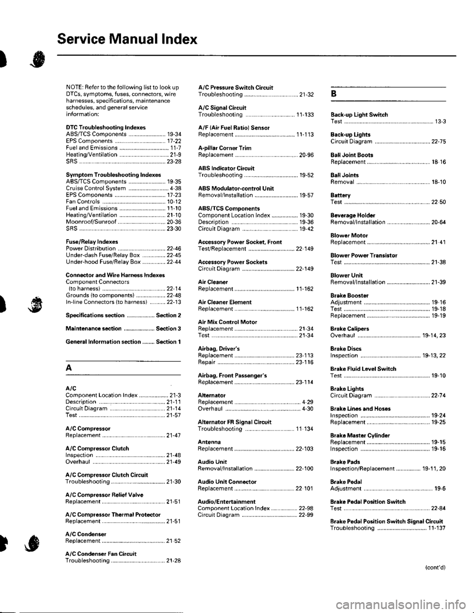
Service Manual lndex
)s
NOTE: Referto the lollowing listto look up A/C Pressure Switch CircuitDTCS, symptoms, fuses, connectors, wire Troubleshooting ......... ...-.-....-...-.-.-....-..21-32 Bharnesses, specifications, maintenanceschedules, and general serviceinlormation:
DTC Troubleshooting Indexes
A/C Signal CircuitTroubleshooting.........................-...... 11-'133 Back-up Light SwitchTest .......................................................... 13'3A/F lAir Fuel Ratiol SensorABS/TCS Components ........................ 19-34 Replacement ....................................... 1 1-113 Back-up Li9ht3EPS Components ................................. '17-22 Circuit DiagramFueland Emissions11-i A-Dillar Corner Trim
ABS Indicator Circuit
Heating/Ventilation ................................ 21-9 Replacement ...............-.....-..............-.... 20,96 Ball Joint BootssRS ........................................................ 23-28Replacement ......
... 19-52 Ball Joints
22-75
18 16
Remova1.............-.......... . ...........18-10Symptom Troubleshooting Indexes TroubleshootingABS/TCSComponents........................ 19 35Cruise Control System ..........................4 38 ABS Modulator-contml UnitEPS Components ................................. 17-23 Bemoval/lnstallation ............................ 19-57 BettervFan Controls10,12
Accessory Powor Socket Front
Blowor Pow€r Transistor
.......22 50
Blower UnitRemoval/lnstallation ............................ 21-39
Fuel and Em issions .............................. 11-10 ABS/TCS ComoonentsHeating/Ventilation..............................21 10 Component Location Index ................. 19-30 Beverage Holder
SRS ........................................................ 23'30 CircuitDiaqram.......................... 19'42Blower MotorReplacement .....21 41
21-38
Power 0istribution ...............................22-46 TesVReplacement .............................. 22'149Under-dash Fuse/Relay Box ............... 22 45Under-hood Fuse/Belay Box ...............22 44 Accessory Power Sockets
Fuse/Relay lndexes
(to harness)
Connector and Wire Harness lndexesComponent Connectors
Circuit Oiagram .................................. 22-149
Air Cleaner......2214 Rep1acemen1.....................................11-162
Air MixControl MotorMeintenence section .................... Section 3 Replacement ......................................... 21'34 Brake CelipersTest......................21-34 Overhaul19-14,23Gene.al lnlormation section........ Section 1
21.57
Airbag. Driver's
Ahernator FR Signal CircuitTroubleshooting .... .........-..........11 134
AntennaReplacement
Inspection ............................................. 19-24Rep|acement................. .................... 19-25
Bieke Meder Cylinder
Irake Discs
A
Replacement ....................................... 23 1 'l3 Inspection .................... ................... 19-13,22Repair ...........-...................................... 23 1 16Brake Fluid Level SwitchAirbag. Front Passenger's TestBeplacement....................................... 23-1 14AIC Brake LightsComponent Location fndex ...................21-3 Altemator CircuitDiagram....................................22-74Description.....................................-....21'1'l Beplacement ................ ........................... 4 29CircuitDiagram....................................21-14 Overhaul .................................................4-30 Brake Lines and Hoses
19.10
A/C CompressolReplacement .......-...-............................. 21 -41
A/C Compr€ssor ClulchRep1acement......................................... 19-15.........22-103 Inspection ............................................. 19-16Inspecton........Overhaul ..........
A/C CondenserReplacement,.,
21-442l-49 Audio Unit
Replacement
Brake PadsRemoval/lnstallation .. ........................22-100 Inspection/Rep1acement................ 19-11,20A/C Compressor Clutch CircuitTroubleshooting ................................... 21-30 Audio Unit Connector Brake Pedal22101 Adjustment..............19,6ArfC Comoressor Relief ValvcReplacement ..........-...-.......................... 21-51 Audio/Entertainment
A/C Compr$sor Thermal Protector Circuit DiagramReplacement............-............................ 21-51
Component Location In dex .................22-9A Test .......-.............. 22-84Breke Pedal Posilion Switch
Brake Pedal Position Switch Signal Clrcuit11-137
.....21 52
A/C Condenser Fan CircuitTroubleshooting ................... . . . . . .....21-28
)s
Troubleshooting
(cont'd)
Page 1135 of 1139

)
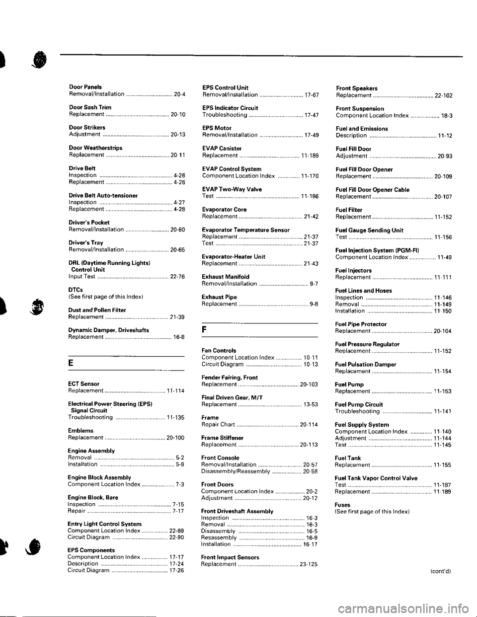
Orive BehInspecaron................ 4-26
Door PanelsRemoval/lnstallation -............................. 20-4
Door Sash TrimRep1acement......................................... 20 10
Door StrikersAdiustment ........................................... 20-13
Door Weatherst psBeplacement...........-............................. 20 1 1
EPS Conirol UnitRemoval/1nsta11ation ..................-......... 17-67
EPS Indicator CircuitTroubleshooting ................................... 17 -47
EPS MotorRemoval/lnstallation .-.......................... 17-49
EVAP CanisterRep1acement......................... ......... 11,189
EVAP Control Syst€mComponentLocation Index ..............'11-170
EVAP Two-Wey ValveTest ..........-.............-............................ 11 186
Evaporetor CoreRep1acement........................ . ... 21-42
Evaporator Tomperature SensorReplacement......................................... 21 -37Test..................................... ..........2137
EvaporrtoFHeater UnitReplacement........................................ 21 43
Exhaust ManifoldRemoval/1nsta11ation ................................ I 7
Exhaust Pipe8ep|acement............................................. 9-8
Front SpeakersRep|acement....................................... 22-102
Front SuspensionComponentLocation Index................... 18-3
Fueland EmissionsDescription ........................................... 11-12
Fuel Fill DoorAdjustment ..........-................................ 20 93
Fuel Fill Door OpenetBeplacement........................ . ............ 20.109
Fuel Fill Door Opener CableReplacement....................................... 20- lO7
Fuel FilterReplacement....................................... 1 1-152
Fuel Gauge Sending UnitTest ......................-.-..........-.................. 11'156
Fuel Injection Syslem (PGM"FIlComponent Location 1ndex................. 11-49
Fuel IniectorsRep1acemen1....................................... 1 1 1 1 l
Fuel Lines and HosesInspection .......................................... 1 1'146Removal ....................... . .. . .... 11-149Insta|1ation .......................................... 1 1 150
FuelPipe ProtectolReplacement....................................... 20-104
Fuel Pressure RegulatotReplacement....................................... 1 1-152
Fuel Pulsation DamperReplacemenl................................... 11 154
Fuel PumpReplacement,,,,,.,.,.,,,.,,,,,,,,,,,,.,.,.,,,..,.. 11-153
Fuel Pump CircuitTroubleshooting -.......-....................... 1 1-141
FuelSupply SystemComponent Location lndex .............. 11 140Adjustment................................... 11-144Test........-...-................. ... ............- 11-145
FuelTankBeplacemenl.............. . ..... .. 11 155
Fuel Tank Vapor ControlValveTest ......................-....... ... . . 11-187Replacement,,.,,...,.,,,.,.,,,,... .. .. 11 189
Fuses{See first page ofthis Index)
)
Rep|acement................. ..................... 4 26
Drive Belt Auto-tensionellnspection ............................................... 4 21Rep1acement.................................... ..4-28
Driver's PocketRemoval/lnstallation -........................... 20-60
Driver's TrayRemoval/lnstallation .........................-.- 20-65
DRL {Daytime Running LightslControl Unitlnput Test .................... ........ . . . ......22-16
DTCs(See first page olthis Index)
Dust and Pollen FillerReplacement......................................... 21-39
Dynamic Damper, DriveshaftsReplacement........................................... 16-8
ECT SensorReplacement.,.,,,.,.,,,,,,,,,,,,,,................ 1 1-1 14
El€ctrical Power Steering IEPS)Signal CircuitTroubleshooting ........ ... .. 11-135
EmblemsReplacement......................-................ 20-100
Engine AssemblyRemova1 .................................................... 5 2Installation ............._.................................. 5-9
Engine Block AssemblyComponent Location Inder ..................... 7.3
Engine Block, BareInspect|onRepair
Fan ControlsComponent Location Index................. 10'l 1Circuit Diagram .. ..... . .. . .................. 10 13
Fender Fairing, FrontReplacement...-................................... 20-103
Final Driven Gear. M/TReplacement.... . . ................................ 13-53
FrameRepair Chan............ ... ....................... 20 11 4
Frame StiffenelReplacement......-................................ 20- J'13
Front ConsoleRemoval/lnstallation ............................ 20 5lDisassembJy/Reassemb|y ................... 20 58
Front DoorsComponent Location Index................... 20-2Adiustment ........................................... 20.12
Front Driveshaft AssemblyInspeclion .................... ... ....16 3Remova1...................-...... ... .....16-3Disassembly ............................... .....165Resassemb|y ................................-......... 16-9Insta11arion ........................ ...... ............ l6 17
Front lmpact SensorsRep1acement............................ ...23 125
................7-15................1 11
)
Entry Light Control SystemComponent Location Index ...............-. 22-89Circuit Dia9ram .................................... 22 90
EPS ComponentsComponent Location 1ndex..........-...... 17-!7Description ........................ ...... ..17-24Circuit Diagram11 26(cont'd)
Page 1137 of 1139

)
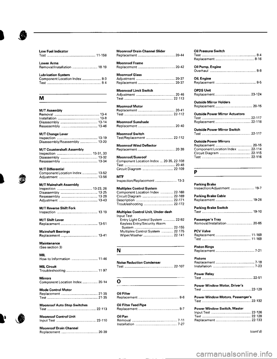
Low Fuel lndicatorTest.....................11-158Moonroof Drain Channel SliderReplacement......................................... 20'44
Moonroof FrameRep1acement,,,,,,,,,,.,.,.,.,.,.,.,,,,,,............ 20 42
MoonroolGlassAdiustment ........................................... 20-37Rep1acement......................................... 20 37
Moonroot Limit SwitchAdjustment ........................................-.- 20 46Test ...................................................... 22 113
Moonrool MotorReplacement....-.................................... 2D-41
Oil Pressure SwitchTest ................-.-........-................................ 8-4Replacement.........-................................. 8-16
Oil Pump, EngineOverhau1 ................................................... 8-8
Oil, EngineReplacement...-................-.-...................... 8-5
OPDS UnitReplacement....................................... 23- 124
Outside Mirror HoldersBeplacement......................................... 20-15
Outside Power Mirror ActuatorsTest ...................................................... 22-117Bepf acement..-.................................... 22-1 14
Outside Power Mirror SwitchTest ..-................................................... 22-111
Outsid€ Power MirrorsReplacement............................ ... .. . . . 20-15Component Location lndex .............. 22- 114Circuit Diagram .................................. 22-115Test -..................................................... 22-116
Lower ArmsRemoval/1nsta11ation............................ 18 19
Lubrication SystemComponent Location Index..................... 8-3Test............................................................ 8 4
M
M/TAssemblyRemoval.......... 13-4 Test...................... 22-1 12lnstallation............. 13-8
.........21,35
Disassembly ......................................... 13-14Resassembly .. ... ................. 13-46
M/TChange Leverlnspection ............................................. 13-19Disassembly 8eassemb1y ................... 13-20
M/T Countershaft AssemblyInspection ....................................... 13 31, 33Disassemb1y ......................................... 13-32Resassemb|y ........................................ 13-34
M/T DifferentialComponentLocation Index................. 13-52Adiuslment ........................................... 13-56
M/T Maifthaft Assembly1nspection ... ................................... 13-23, 26Disassembly ......................................... 13 25Resassembly ........................................ 13 28Adjustment ........................................... 13-43
M/T Reverse Shift ForkInspection .................... ........................ l3 19
M/T Shift LevelReplacement......................................... 13-51
Mainshaft BearingsReplacement....,.................................... 13 41
MairtenancelSee section 3)
MILHow to Informatron ............................. 1 1.46
MIL CircuitTroubleshooting .......... .- . . . . ......... 11 97
MirrorsComponentLocation Index................. 20'14
Mode Control MotorReplacement
Moonrool SunshadeRep1acement....................... . . ............. 20 40
Moonroof SwitchTesVRep1acement .............................. 22- l 12
Mooniool Wind Def lectorReplacement.......................-................. 20-38
Moonroof/SunroofComponent Location Index ... 20-35, 22-108Test ........................................................ 20-48Cf rcuit Diagram .................................. 22- 109
MTFInspection/Rep1acement. .......... ........... 13-3
Muhiplex Control SystemComponentLocation lndex ..............22 168Circuit Diagram .................................. 22-1690escription ......................................... 22-17 1Troubleshooting ................................ 22-17 2
Muliiplex Control Unit, Under-dashInput TestEntry Light Control Sysiem ............. 22-92Keyless Entry/Security AlarmSystern .-....................................... 22-155MultiplexControl System .............22 115Wiper/Washer................................. 22'1 41
NoiseTest,,Reduction Condenser
Parking ErakeInspection Adjustment ........... .............. 19-7
Parking Brake CableRep1acement......................................... 19-26
Parking Erake Switch
P
l
Test ...................... 19-10
Test............................... . ...........2135
Moonroof Auto Stop SwitchosTest ...................................................... 22'113
Moon.oot Control Unillnput Test ............................................ 22-110
Moonroof Drein ChannelBeplacement ... . ....... ......................... 20 39
Oil Filte]Replacement............................................. 8-6
Oil Filter Feed PipeReplacement............... . ..-,...,.,,,,,,,,8-7
Oil PanRemoval .............,.,,,,,,,,,,,,.,.,,,.........-....... 7 1 1lnstallation .............................................. 7 -27
Passenger's TraVRemoval/lnstallation ............................ 20-65
PCV ValveBeplacement....................................... 1 1'169Test........................................... l1 169
Piston Rings8ep1acement................................-.-...-.- 7-21
PistonsReplacement...................-....................... 7-181nsta|1ation ...................................... ...1-23
Power R€layTest ...............-.-...................................... 22-51
Power Window Motor, Driver'stesl.....,,,, .,.,,,............
Power Window Motors, Passenger's
Power Window Switch, Masterlnput Test ..........-.........-....................... 22-126Tesr ....... . ............................................ 22 124Replacement....................................... 22-133
N
..............22 101
o
l' ,e
(cont'd)