Page 103 of 158
The air cleaner element is inside the
air cleaner housing on the passenger’s
side of the engine compartment.
To replace it:Unsnap the f our hold-down clamps
and remove the air cleaner
housing cover.
Remove the old air cleaner
element.
Caref ully clean the inside of the
air cleaner housing with a damp
rag.Place the new air cleaner element
in the air cleaner housing.
Reinstall the air cleaner housing
cover, snap the four hold-down
clamps back into place.
1. 3. 4. 5.
2.
Replacement
A ir Cleaner Element (4-cylinder Models)
Maint enance270
AAIIRRCCLLEEAANNEERREELLEEMMEENNTT
CCLLAAMMPPSS
Page 104 of 158
Place the new air cleaner element
in the air cleaner housing.
Loosen the f our bolts and remove
the air cleaner housing cover.
Remove the old air cleaner
element. Reinstall the air cleaner housing
cover, tighten the f our bolts.
To replace it:
The air cleaner element is inside the
air cleaner housing on the driver’s
side of the engine compartment.
Caref ully clean the inside of the
air cleaner housing with a damp
rag.
1. 3.
4. 5.
2.
Replacement
A ir Cleaner Element (6-cylinder Models)
Maint enance271
AAIIRRCCLLEEAANNEERREELLEEMMEENNTT
BBOOLLTTSS
Page 106 of 158

Tightening torque:
Put the new spark plug into t")
�´ �µ
Torque the spark plug. (If you do
not have a torque wrench, tighten
the spark plug two-thirds of a turn
af ter it contacts the cylinder head.)
Tightening torque:
Put the new spark plug into the
socket; then screw it into the hole.
Screw it in by hand so you do not
crossthread it.
Install the ignition coil. Reinstall
the hexagon socket head cap bolt.Push the wire connector onto the
ignition coil. Make sure it locks in
place.
Spark Plug Gap: Reinstall the cover on the front
cylinder bank while putting its
mounting clip in the hole on the
passenger’s side. Secure the cover
by turning the heads of the two
holding clips one-quarter turn
clockwise with a f lat-tipped
screwdriver.
Repeat this procedure f or the
other f ive spark plugs.
NGK:
DENSO:
6. 7.
8.9.
10. 11.
Specif ications:
Spark Plugs (6-cylinder Models)
Maint enance275
13 lbf·ft (18 N·m , 1.8 kgf·m) 0.04 in (1.1 mm)PKJ16CR-L11
PZFR5F-11
0
0.1 mm
Tighten the spark plugs caref ully. A
spark plug that is too loose can
overheat and damage the engine.
Overtightening can cause damage to
the threads in the cylinder head.
Page 112 of 158

Testthelightstomakesurethe
new bulb is working.
Insert the socket back into the
headlight assembly. Turn it
clockwise to lock it in place.
Install the new bulb in the socket.
Turn it clockwise to lock it in place.
Remove the burned out bulb f rom
thesocketbypushingitinand
turning the bulb counterclockwise
until it unlocks.
Remove the socket from the
headlight assembly by turning it
one-quarter turn counterclockwise.
If you are changing the bulb on
the driver’s side, start the engine,
turn the steering wheel all the way
to the right, and turn off the
engine. If you are changing the
bulb on the passenger’s side, turn
the steering wheel to the left.
Use a f lat-tipped screwdriver to
remove the holding clip f rom the
inner f ender.
Pull the inner f ender cover away
f rom the f ender and bumper.
Put the inner f ender cover in place.
Install the holding clip. Lock it in
place by pushing on the center.
1.
3.
2. 4. 5. 6. 7. 8. 9.
Replacing Front Turn Signal and
Side Marker L ight Bulbs
Lights
Maint enance293
HHOOLLDDIINNGGCCLLIIPP
Page 125 of 158
�µ
�´
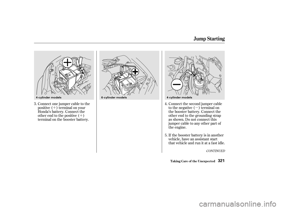
�´ Connect the second jumper cable
to the negative ( ) terminal on
the booster battery. Connect the
other end to the grounding strap
as shown. Do not connect this
jumper cable to any other part of
the engine.
If the booster battery is in another
vehicle, have an assistant start
that vehicle and run it at a fast idle.
Connect one jumper cable to the
positive ( ) terminal on your
Honda’s battery. Connect the
other end to the positive ( )
terminal on the booster battery.
5.
3.
4.
CONT INUED
Jump Starting
T aking Care of t he Unexpect ed321
44--ccyylliinnddeerrmmooddeellss66--ccyylliinnddeerrmmooddeellss44--ccyylliinnddeerrmmooddeellss
Page 127 of 158

If the temperature gauge stays at
the red mark, turn of f the engine.
Wait until you see no more signs
of steam or spray, then open thehood.
If there was no coolant in the
reserve tank, you may also have to
add coolant to the radiator. Let the
engine cool down until the pointerreaches the middle of the tempera-
ture gauge, or lower, bef ore check-
ing the radiator.
Using gloves or a large heavy
cloth, turn the radiator cap
counterclockwise, without pushing
down, to the f irst stop. This
releases any remaining pressure in
the cooling system. After the
pressure releases, push down on
the cap and turn it until it comes
off.
If you don’t f ind an obvious leak,
check the coolant level in the
radiator reserve tank (see page
). If the level is below the
MIN mark, add coolant to halfway
between the MIN and MAX marks. Start the engine and set the
temperature control dial to
maximum (climate control to
FULL AUTO at 90°F/32°C). Add
coolant to the radiator up to the
base of the f iller neck. If you do
not have the proper coolant
mixture available, you can add
plain water. Remember to have
the cooling system drained and
ref illed with the proper mixture as
soon as you can.
If the temperature stays normal,
check the coolant level in the
radiator reserve tank. If it has
gone down, add coolant to the
MAX mark. Put the cap back on
tightly.
Look f or any obvious coolant leaks,
such as a split radiator hose.
Everything is still extremely hot,
so use caution. If you f ind a leak, it
must be repaired bef ore you
continue driving (see
on page ). Put the radiator cap back on
tightly. Run the engine and watch
the temperature gauge. If it goes
back to the red mark, the engine
needs repair. (See on page .)
4. 5.
6. 7. 8. 9.
11.12.10.
336
200 336
T aking Care of t he Unexpect ed
If Your Engine Overheats
Emergency
Towing
Emergency
Towing
324
Removing the radiator cap
while the engine is hot can
cause the coolant to spray out,
seriously scalding you.
Always let the engine and
radiator cool down before
removing the radiator cap.
Page 133 of 158
The Transmission Number is on a
label on top of the transmission.
The Engine Number is stamped into
the engine block. It is on the f ront.
Identif ication Numbers
T echnical Inf ormation
4-cylinder Models 6-cylinder Models
341
MMAANNUUAALLTTRRAANNSSMMIISSSSIIOONNNNUUMMBBEERRAAUUTTOOMMAATTIICCTTRRAANNSSMMIISSSSIIOONNNNUUMMBBEERR
EENNGGIINNEENNUUMMBBEERRAAUUTTOOMMAATTIICCTTRRAANNSSMMIISSSSIIOONNNNUUMMBBEERR
EENNGGIINNEENNUUMMBBEERR
Page 134 of 158

�µ
�µ �µ�µ �µ �µ�µ�µ�µ�µ�µ�µ�µ�µ�µ �µ �µ
�Î�Î�Î
�Î
�Î
�Î�Î�Î
CONT INUED
Specif ications
T echnical Inf ormation343
Battery
Fuses Alignment
Engine
Lights
3.39 x 3.82 in (86.0 x 97.0 mm)137.5 cu-in (2,254 cm
)
12 V 60 W (HB3)
12 V 51 W (HB4)
12 V 24/2.2 CP
12 V 3 CP
12 V 21 W
12 V 21/5 W
12 V 3 CP
12 V 21 W
12 V 21 W
12 V
12 V
12 V
12 V
12 V
3CP7W5W
2CP
1.8 W
12 V
12 V 52 AH/5 HR
55 AH/5 HR
3°00’0°30’0°
0.08 in (2.0 mm)
0.00 in (0.0 mm)
3.39 x 3.39 in (86.0 x 86.0 mm)
182.8 cu-in (2,997 cm)
8.8 : 1
9.3 : 1
9.4 : 1
Capacity
Interior
Under-hood Toe-in
CamberCaster
Type
BorexStroke
Displacement
Compression ratio
Spark plugs
Water cooled 4-stroke SOHC,
SOHC VTEC 4-cylinder, SOHC
6-cylinder (V6), gasoline engine
Headlights
Front turn signal/side marker
lights
Front parking lights
Rear turn signal lights
Stop/Taillights
Taillight
High-mount brake light
Back-up lights
License plate lights
Ceiling light
Trunk lights
Door courtesy lights
Vanity mirror light
See page 335 or the fuse label
attached to the inside of the fuse
box door on each side of the
dashboard.
See page 334 or the fuse box
cover. See spark plug maintenance sec-
tion pages 273 and 275 .
FrontRear
FrontRear
Front
HighLow
4-cylinder
6-cylinder
1: DX,ValuePackage
2: LX,EX,SE
3 : 6-cylinder models
3
3
123