Page 53 of 264
CENTER CONSOLE (IF EQUIPPED)
Your vehicle may be equipped with a variety of console features. These
include:
•Utility compartment with
cassette/CD holder
•Coin holder
•Pen holder
•Writing surface
Use only soft cups in the
cupholder. Hard objects can
injure you in a collision.
•Utility compartment
•Pen holder
•Space for lap-top computer
TRIP COMPUTER (IF EQUIPPED)
The trip computer tells you about the condition of your vehicle through
a constant monitor of vehicle systems. You may select display features on
the trip computer for a display of status.
The appearance of your vehicle’s trip computer may differ depending on
your vehicle’s option package, but the functions are the same.
Driver Controls
53
Page 54 of 264

The trip computer only operates with the ignition in the ON position.
Trip computer features are as follows:
Selectable features
English/metric display
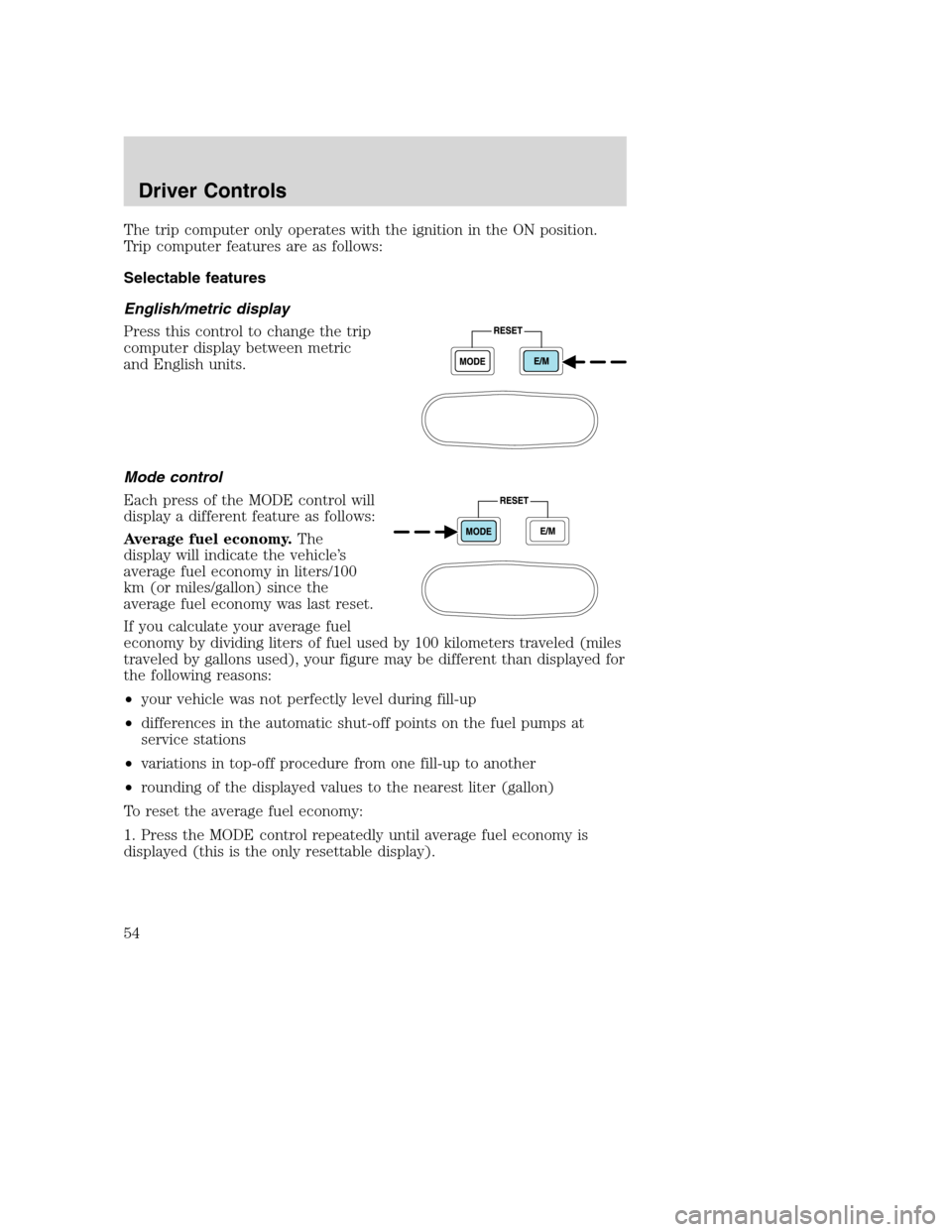
Press this control to change the trip
computer display between metric
and English units.
Mode control
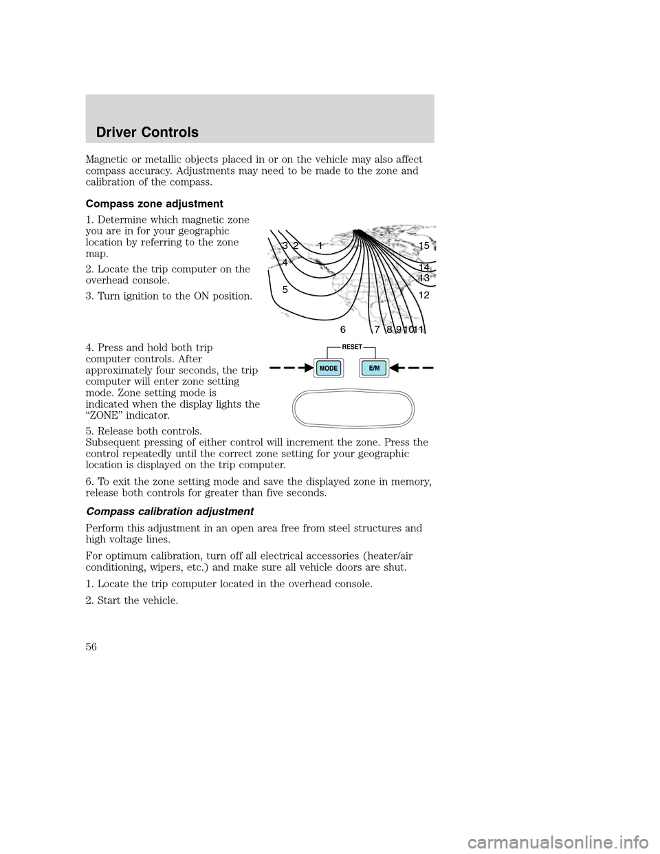
Each press of the MODE control will
display a different feature as follows:
Average fuel economy.The
display will indicate the vehicle’s
average fuel economy in liters/100
km (or miles/gallon) since the
average fuel economy was last reset.
If you calculate your average fuel
economy by dividing liters of fuel used by 100 kilometers traveled (miles
traveled by gallons used), your figure may be different than displayed for
the following reasons:
•your vehicle was not perfectly level during fill-up
•differences in the automatic shut-off points on the fuel pumps at
service stations
•variations in top-off procedure from one fill-up to another
•rounding of the displayed values to the nearest liter (gallon)
To reset the average fuel economy:
1. Press the MODE control repeatedly until average fuel economy is
displayed (this is the only resettable display).
Driver Controls
54
Page 56 of 264

Magnetic or metallic objects placed in or on the vehicle may also affect
compass accuracy. Adjustments may need to be made to the zone and
calibration of the compass.
Compass zone adjustment
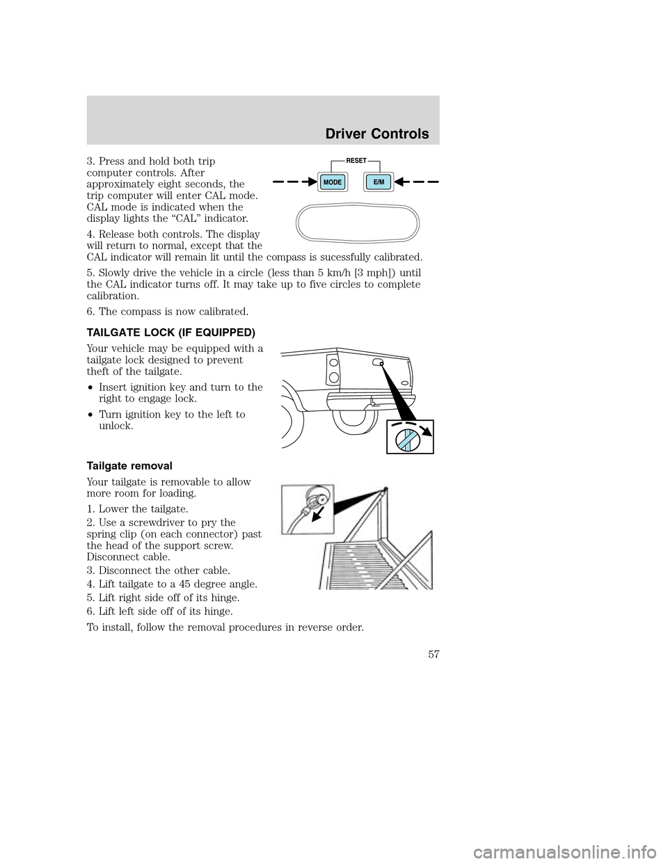
1. Determine which magnetic zone
you are in for your geographic
location by referring to the zone
map.
2. Locate the trip computer on the
overhead console.
3. Turn ignition to the ON position.
4. Press and hold both trip
computer controls. After
approximately four seconds, the trip
computer will enter zone setting
mode. Zone setting mode is
indicated when the display lights the
“ZONE” indicator.
5. Release both controls.
Subsequent pressing of either control will increment the zone. Press the
control repeatedly until the correct zone setting for your geographic
location is displayed on the trip computer.
6. To exit the zone setting mode and save the displayed zone in memory,
release both controls for greater than five seconds.
Compass calibration adjustment
Perform this adjustment in an open area free from steel structures and
high voltage lines.
For optimum calibration, turn off all electrical accessories (heater/air
conditioning, wipers, etc.) and make sure all vehicle doors are shut.
1. Locate the trip computer located in the overhead console.
2. Start the vehicle.
1 2 3
4
5
6 7 8 9 101112 13 14 15
Driver Controls
56
Page 57 of 264

3. Press and hold both trip
computer controls. After
approximately eight seconds, the
trip computer will enter CAL mode.
CAL mode is indicated when the
display lights the “CAL” indicator.
4.
Release both controls. The display
will return to normal, except that the
CAL indicator will remain lit until the compass is sucessfully calibrated.
5. Slowly drive the vehicle in a circle (less than 5 km/h [3 mph]) until
the CAL indicator turns off. It may take up to five circles to complete
calibration.
6. The compass is now calibrated.
TAILGATE LOCK (IF EQUIPPED)
Your vehicle may be equipped with a
tailgate lock designed to prevent
theft of the tailgate.
•Insert ignition key and turn to the
right to engage lock.
•Turn ignition key to the left to
unlock.
Tailgate removal
Your tailgate is removable to allow
more room for loading.
1. Lower the tailgate.
2. Use a screwdriver to pry the
spring clip (on each connector) past
the head of the support screw.
Disconnect cable.
3. Disconnect the other cable.
4. Lift tailgate to a 45 degree angle.
5. Lift right side off of its hinge.
6. Lift left side off of its hinge.
To install, follow the removal procedures in reverse order.
Driver Controls
57