2002 FORD F SERIES MOTORHOME AND COMMERCIAL CHASSIS tow
[x] Cancel search: towPage 3 of 104
Fuel pump shut-off switchIn the event of an accident the
safety switch will automatically cut off the fuel supply to the
engine. The switch can also be activated through sudden vibration (e.g.
collision when parking). To reset the switch, refer to theFuel pump
shut-off switchin theRoadside emergencieschapter.
SAFETY AND ENVIRONMENT PROTECTION
Warning symbols in this guide
How can you reduce the risk of personal injury and prevent possible
damage to others, your vehicle and its equipment? In this guide, answers
to such questions are contained in comments highlighted by the warning
triangle symbol. These comments should be read and observed.
Warning symbols on your vehicle
When you see this symbol, it is
imperative that you consult the
relevant section of this guide before
touching or attempting adjustment
of any kind.
Protecting the environment
We must all play our part in
protecting the environment. Correct
vehicle usage and the authorized
disposal of waste cleaning and
lubrication materials are significant
steps towards this aim. Information in this respect is highlighted in this
guide with the tree symbol.
Introduction
3
Page 7 of 104
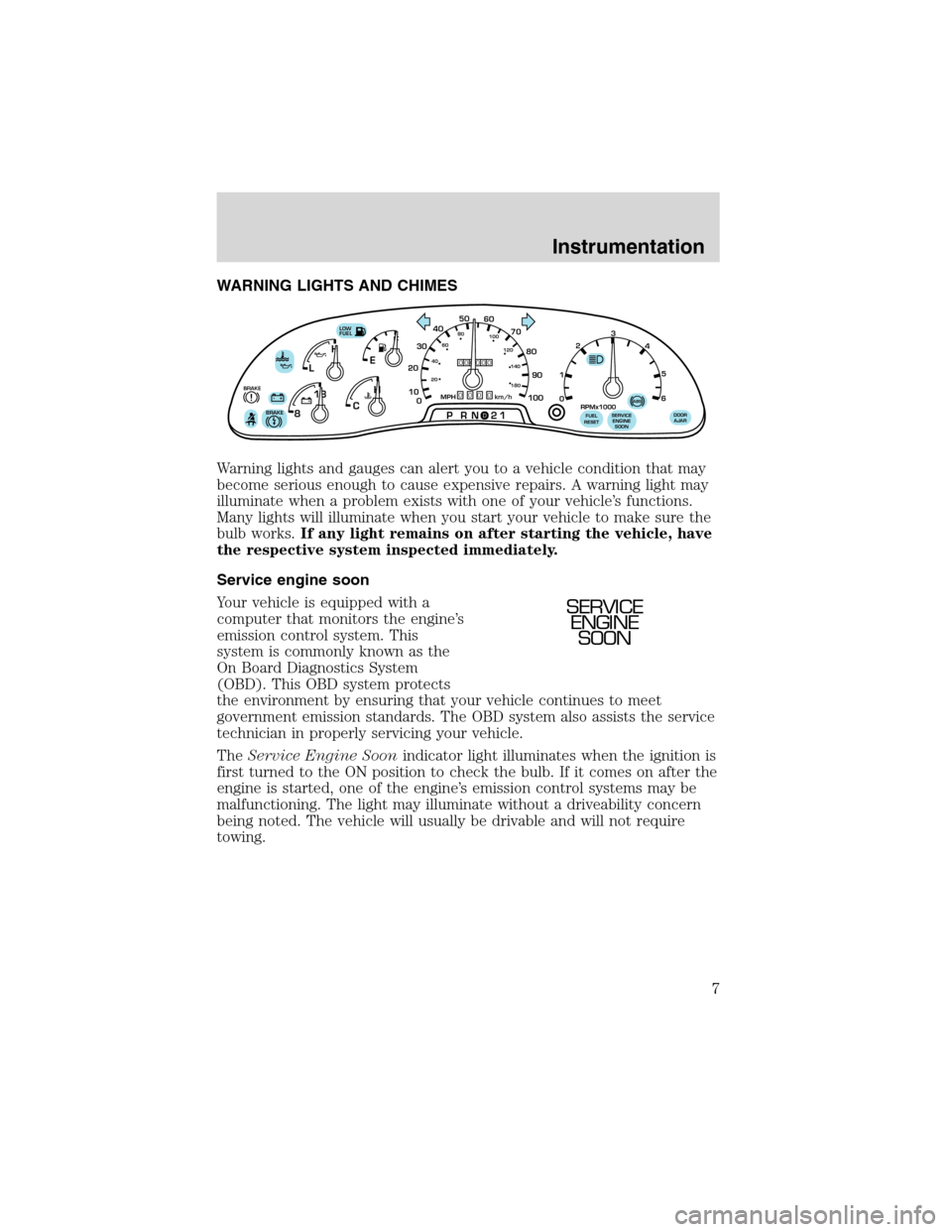
WARNING LIGHTS AND CHIMES
Warning lights and gauges can alert you to a vehicle condition that may
become serious enough to cause expensive repairs. A warning light may
illuminate when a problem exists with one of your vehicle’s functions.
Many lights will illuminate when you start your vehicle to make sure the
bulb works.If any light remains on after starting the vehicle, have
the respective system inspected immediately.
Service engine soon
Your vehicle is equipped with a
computer that monitors the engine’s
emission control system. This
system is commonly known as the
On Board Diagnostics System
(OBD). This OBD system protects
the environment by ensuring that your vehicle continues to meet
government emission standards. The OBD system also assists the service
technician in properly servicing your vehicle.
TheService Engine Soonindicator light illuminates when the ignition is
first turned to the ON position to check the bulb. If it comes on after the
engine is started, one of the engine’s emission control systems may be
malfunctioning. The light may illuminate without a driveability concern
being noted. The vehicle will usually be drivable and will not require
towing.
F
E
CH H
L
18
8
PRN 21LOW
FUEL
BRAKE!+ -+ -000000000
0
50
60
70
20
10
0 3040
80
90
100
20406080
100
120
140
180
MPH km/h
1
02
RPMx1000
3
4
5
6
SERVICE
ENGINE
SOONABSFUEL
RESETDOOR
AJARBRAKE
SERVICE
ENGINE
SOON
Instrumentation
7
Page 15 of 104
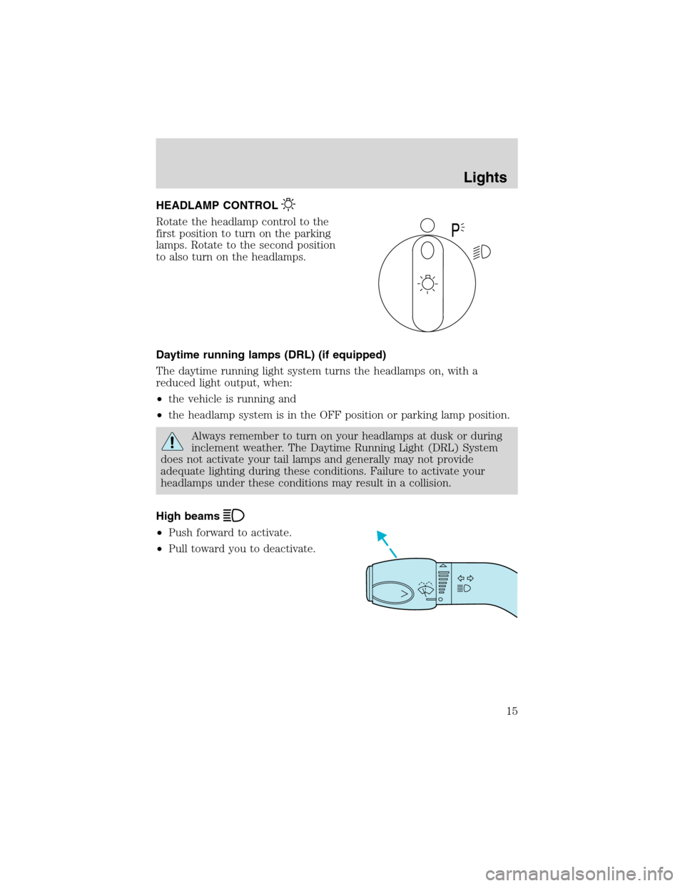
HEADLAMP CONTROL
Rotate the headlamp control to the
first position to turn on the parking
lamps. Rotate to the second position
to also turn on the headlamps.
Daytime running lamps (DRL) (if equipped)
The daytime running light system turns the headlamps on, with a
reduced light output, when:
•the vehicle is running and
•the headlamp system is in the OFF position or parking lamp position.
Always remember to turn on your headlamps at dusk or during
inclement weather. The Daytime Running Light (DRL) System
does not activate your tail lamps and generally may not provide
adequate lighting during these conditions. Failure to activate your
headlamps under these conditions may result in a collision.
High beams
•Push forward to activate.
•Pull toward you to deactivate.
P
Lights
15
Page 16 of 104
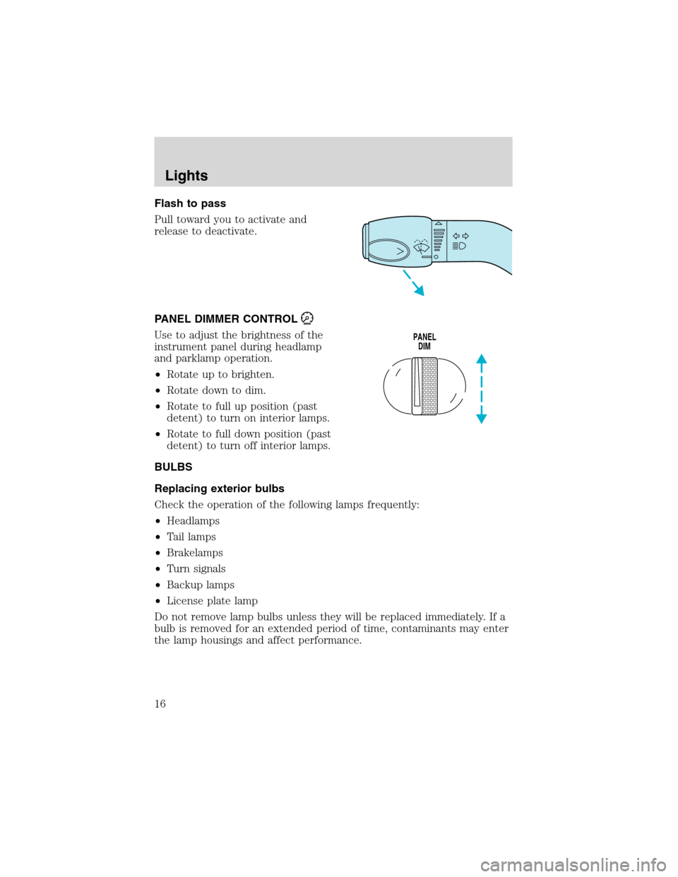
Flash to pass
Pull toward you to activate and
release to deactivate.
PANEL DIMMER CONTROL
Use to adjust the brightness of the
instrument panel during headlamp
and parklamp operation.
•Rotate up to brighten.
•Rotate down to dim.
•Rotate to full up position (past
detent) to turn on interior lamps.
•Rotate to full down position (past
detent) to turn off interior lamps.
BULBS
Replacing exterior bulbs
Check the operation of the following lamps frequently:
•Headlamps
•Tail lamps
•Brakelamps
•Turn signals
•Backup lamps
•License plate lamp
Do not remove lamp bulbs unless they will be replaced immediately. If a
bulb is removed for an extended period of time, contaminants may enter
the lamp housings and affect performance.PANEL
DIM
Lights
16
Page 32 of 104
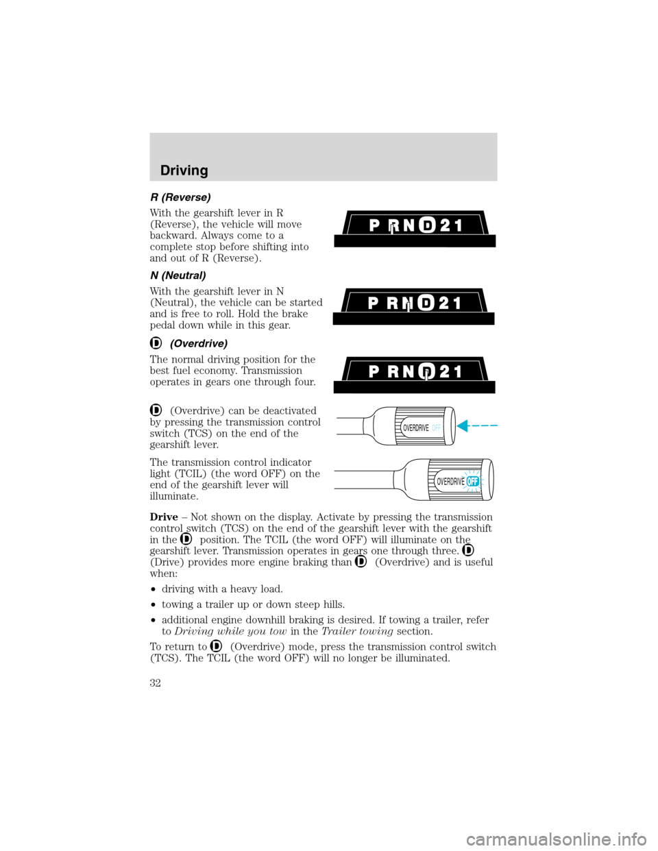
R (Reverse)
With the gearshift lever in R
(Reverse), the vehicle will move
backward. Always come to a
complete stop before shifting into
and out of R (Reverse).
N (Neutral)
With the gearshift lever in N
(Neutral), the vehicle can be started
and is free to roll. Hold the brake
pedal down while in this gear.
(Overdrive)
The normal driving position for the
best fuel economy. Transmission
operates in gears one through four.
(Overdrive) can be deactivated
by pressing the transmission control
switch (TCS) on the end of the
gearshift lever.
The transmission control indicator
light (TCIL) (the word OFF) on the
end of the gearshift lever will
illuminate.
Drive– Not shown on the display. Activate by pressing the transmission
control switch (TCS) on the end of the gearshift lever with the gearshift
in the
position. The TCIL (the word OFF) will illuminate on the
gearshift lever. Transmission operates in gears one through three.
(Drive) provides more engine braking than(Overdrive) and is useful
when:
•driving with a heavy load.
•towing a trailer up or down steep hills.
•additional engine downhill braking is desired. If towing a trailer, refer
toDriving while you towin theTrailer towingsection.
To return to
(Overdrive) mode, press the transmission control switch
(TCS). The TCIL (the word OFF) will no longer be illuminated.
OVERDRIVEOFF
OVERDRIVE
Driving
32
Page 34 of 104
Driving through deep water where the transmission vent tube is
submerged may allow water into the transmission and cause
internal transmission damage.
VEHICLE LOADING
Your vehicle’s load capacity is designed by weight, not volume, so you
cannot necessarily use all available space with large or heavy loads.
Maximum safe vehicle weights as well as tire, rim sizes and inflation
pressures are specified for your vehicle on the Safety Compliance
Certification Label. A Certification Label was supplied by Ford Motor
Company to the Motorhome Manufacturer. The manufacturer uses this
information and supplies a Certification Label which is located inside the
vehicle to the left of the driver.
Before loading a vehicle, familiarize yourself with the following terms:
•Base Curb Weight:Weight of the vehicle including any standard
equipment, fluids, lubricants, etc. It does not include occupants or
aftermarket equipment.
•Payload:Combined maximum allowable weight of cargo, occupants
and optional equipment. The payload equals the gross vehicle weight
rating minus base curb weight.
•GVW (Gross Vehicle Weight):Base curb weight plus payload
weight. The GVW is not a limit or a specification.
•GVWR (Gross Vehicle Weight Rating):Maximum permissable total
weight of the base vehicle, occupants, optional equipment and cargo.
The GVWR is specific to each vehicle and is listed on the Certification
Label, located near the driver’s seat or on the driver’s door pillar.
•GAWR (Gross Axle Weight Rating):Carrying capacity for each axle
system. The GAWR is specific to each vehicle and is listed on the
Certification Label, located near the driver’s seat or on the driver’s
door pillar.
•GCWR (Gross Combined Weight Rating):Maximum permissable
combined weight of towing vehicle (including occupants and cargo)
and the loaded trailer.
Driving
34
Page 35 of 104
•Maximum Trailer Weight Rating:Maximum weight of a trailer the
loaded vehicle (including occupants and cargo) is permitted to tow.
The maximum trailer weight rating is determined by subtracting the
vehicle curb weight for each engine/transmission combination, any
required option weight for trailer towing and the weight of the driver
from the GCWR for the towing vehicle.
•Trailer Weight Range:Specified weight range that the trailer must
fall within that ranges from zero to the maximum trailer weight rating.
Remember to figure in the tongue load of your loaded trailer when
figuring the total weight.
Do not exceed the GVWR or the GAWR specified on the
certification label.
Do not use replacement tires with lower weight capacities than the
originals because they may lower the vehicle’s GVWR and GAWR
limitations. Replacement tires with a higher weight limit than the
originals do not increase the GVWR and GAWR limitations.
Calculating the load your vehicle can carry/tow
1. Use the appropriate maximum gross combined weight rating (GCWR)
chart to find the maximum GCWR for your type engine and rear axle
ratio.
2. Weigh your vehicle as you customarily operate the vehicle without
cargo. To obtain correct weights, try taking your vehicle to a shipping
company or an inspection station for trucks.
3. Subtract your loaded vehicle weight from the maximum GCWR on the
following charts. This is the maximum combined cargo and trailer weight
your vehicle can carry/tow and must fall below the maximum shown
under maximum trailer weight on the chart. Refer to the definition of
Maximum Trailer Weight below Vehicle Loading in this chapter to
determine the maximum trailer weight permitted for a loaded vehicle.
Driving
35
Page 36 of 104
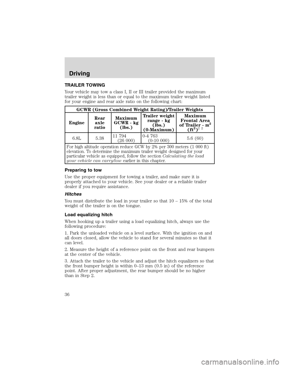
TRAILER TOWING
Your vehicle may tow a class I, II or III trailer provided the maximum
trailer weight is less than or equal to the maximum trailer weight listed
for your engine and rear axle ratio on the following chart:
GCWR (Gross Combined Weight Rating)/Trailer Weights
EngineRear
axle
ratioMaximum
GCWR - kg
(lbs.)Trailer weight
range - kg
(lbs.)
(0-Maximum)Maximum
Frontal Area
of Trailer - m
2
(ft2)22
6.8L 5.3811 794
(26 000)0-4 763
(0-10 000)5.6 (60)
For high altitude operation reduce GCW by 2% per 300 meters (1 000 ft)
elevation. To determine the maximum trailer weight designed for your
particular vehicle as equipped, follow the sectionCalculating the load
your vehicle can carry/towearlier in this chapter.
Preparing to tow
Use the proper equipment for towing a trailer, and make sure it is
properly attached to your vehicle. See your dealer or a reliable trailer
dealer if you require assistance.
Hitches
You must distribute the load in your trailer so that 10 – 15% of the total
weight of the trailer is on the tongue.
Load equalizing hitch
When hooking up a trailer using a load equalizing hitch, always use the
following procedure:
1. Park the unloaded vehicle on a level surface. With the ignition on and
all doors closed, allow the vehicle to stand for several minutes so that it
can level.
2. Measure the height of a reference point on the front and rear bumpers
at the center of the vehicle.
3. Attach the trailer to the vehicle and adjust the hitch equalizers so that
the front bumper height is within 0–13 mm (0.5 in) of the reference
point. After proper adjustment, the rear bumper should be no higher
than in Step 2.
Driving
36