Page 210 of 312

The fuses are coded as follows:
Fuse/Relay
LocationFuse Amp
RatingPassenger Compartment Fuse
Panel Description
1 30A Radio Sense, 4x4, ABS Control
Module
2 20A Folding Mirror, Moon Roof,
Heated Seats, Moon roof
3 20A Radio, Amplifier, Power Antenna
4 5A Digital Transmission Range Sensor
5 15A Flasher Relay (Turn, Hazards)
6 10A Right Horn
7 15A Heated Mirrors
8 30A Washer Pump Relays (Front and
Rear), Front Wiper Control
9 15A Rear Wiper Coil and Contact
10 10A Heated Backlight Relay Coil,
Heated Seat Module, Temp Blend
Actuator, A/C Clutch Contact
11 Ð Not Used
12 5A Foglamp Switch,4x4module
13 5A Over Drive Cancel Switch, GEM
Start, Flex Fuel Sender
14 5A PATS Module
15 5A 4 x 4, Memory Seat Disable
16 5A Power Mirror, Security Module
(turn), Manual Climate Control
17 15A Delayed Acc. Coil, Battery Saver,
Interior Lamps
18 10A Left Horn
19 Ð Not Used
20 5A Memory Module, GEM Module
21 5A Instrument Cluster, Compass,
Flasher Coil
22 Ð Not Used
23 15A Brake Pedal Position Switch
24 15A Cigar Lighter, OBD II
Roadside emergencies
210
Page 211 of 312
Fuse/Relay
LocationFuse Amp
RatingPassenger Compartment Fuse
Panel Description
25 5A Mode, Temperature Actuator,
Auxiliary Climate Control, Trailer
Tow Battery Charge, Moon Roof
26 7.5A Park Aid, Brake Shift Interlock,
Approach Lamp Relay Coil
27 7.5A Electronic Compass Mirror,
Security Module, Digital
Transmission Range Sensor -
Backup Lamps
28 10A Air Bag Diagnostics
29 5A 4 x 4, GEM Module signal, ABS
Control Module, Moon Roof
30 5A Daytime Running Lamps (DRL),
Remote Solenoid, DEATC Climate
Controller
Roadside emergencies
211
Page 212 of 312
Passenger compartment fuse panel (top side)
These relays are located on the reverse side of the passenger
compartment fuse panel. To access the relays you must remove the
passenger compartment fuse panel.
Fuse/Relay Location Description
Relay 1 Flasher Relay
Relay 2 Rear Defrost
Relay 3 Delayed Accessory Relay
Relay 4 Front Washer Pump
Relay 5 Battery Saver
Relay 6 Rear Washer Pump
Relay 7 Interior Lamps
Roadside emergencies
212
Page 213 of 312
Power distribution box
The power distribution box is
located in the engine compartment.
The power distribution box contains
high-current fuses that protect your
vehicle's main electrical systems
from overloads.
Always disconnect the battery before servicing high current
fuses.
Always replace the cover to the Power Distribution Box before
reconnecting the battery or refilling fluid reservoirs.
If the battery has been disconnected and reconnected, refer to the
Batterysection of theMaintenance and carechapter.
Roadside emergencies
213
Page 214 of 312
The high-current fuses are coded as follows:
Fuse/Relay
LocationFuse Amp
RatingPower Distribution Box
Description
1 60A** PJB
2 20A** Door Locks
3 20A** GCC Pusher Fan (export only)
4 30A** Heated Backlight
5 40A** ABS
6 60A** Circuit Breaker
7 20A** Power Point #2
8 Ð Not Used
9 20A** Power Point #1
10 20A** ABS Module
11 40A** PTEC
12 50A** Ignition Relay
13 30A** Trailer Tow Battery
14 10A* Fog Lamps
15 5A* Memory
16 15A* Headlamp Switch
17 20A*4 x 4 (v-batt 2)
18 20A*4 x 4 (v-batt 1)
19 20A** High Beam Relay
20 30A** Electric Brake
21 Ð Not Used
22 20A** Autolmap; Low Beam
23 30A** Ignition Switch
24 10A* Rear Fog Lamps
25 20A* Security Module (horns)
26 15A* Fuel Pump
27 20A* Trailer Tow Lamps
28 10A* Daytime Running Lamps (DRL)
29 60A** PJB
30 Ð Not Used
31 Ð Not Used
32 Ð Not Used
33 30A** Auxiliary Blower Motor
Roadside emergencies
214
Page 216 of 312
Rear Relay Box
The relay box is located on the rear passenger side quarter trim panel.
To access this box you must remove the trim panel.
The relays are coded as follows:
Fuse/Relay Location Description
Relay 14 Rear fog lamps-export
Relay 15 Trailer Tow back up lamps
Relay 16 Not Used
Relay 17 Rear Wipers
Relay 18 Trailer Tow Stop EAO
Relay 19 Trailer Tow Park Lamps
Relay 20 Trailer Tow Battery Charge
Relay 21 Not Used
Relay 22 Approach Lamps
Relay 23 Not Used
Diode 3 Not Used
Diode 4 Not Used
Roadside emergencies
216
Page 222 of 312

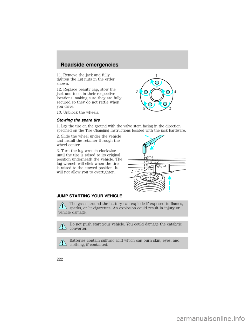
11. Remove the jack and fully
tighten the lug nuts in the order
shown.
12. Replace beauty cap, stow the
jack and tools in their respective
locations, making sure they are fully
secured so they do not rattle when
you drive.
13. Unblock the wheels.
Stowing the spare tire
1.Lay the tire on the ground with the valve stem facing in the direction
specified on the Tire Changing Instructions located with the jack hardware.
2. Slide the wheel under the vehicle
and install the retainer through the
wheel center.
3. Turn the lug wrench clockwise
until the tire is raised to its original
position underneath the vehicle. The
lug wrench will click when the tire
is raised to the stowed position. It
will not allow you to overtighten.
JUMP STARTING YOUR VEHICLE
The gases around the battery can explode if exposed to flames,
sparks, or lit cigarettes. An explosion could result in injury or
vehicle damage.
Do not push start your vehicle. You could damage the catalytic
converter.
Batteries contain sulfuric acid which can burn skin, eyes, and
clothing, if contacted.
1
4 3
2 5
Roadside emergencies
222
Page 223 of 312

Do not attempt to push start your vehicle. Automatic
transmissions do not have push-start capability.
Preparing your vehicle
When the battery is disconnected or a new battery is installed, the
transmission must relearn its adaptive strategy. As a result of this, the
transmission may shift firmly. This operation is considered normal and
will not effect function or durability of the transmission. Over time, the
adaptive learning process will fully update transmission operation to its
optimum shift feel.
1.Use only a 12±volt supply to start your vehicle.
2. Do not disconnect the battery of the disabled vehicle as this could
damage the vehicle's electrical system.
3.
Park the booster vehicle close to the hood of the disabled vehicle
making sure the two vehiclesdo nottouch. Set the parking brake on both
vehicles and stay clear of the engine cooling fan and other moving parts.
4. Check all battery terminals and remove any excessive corrosion before
you attach the battery cables. Ensure that vent caps are tight and level.
5. Turn the heater fan on in both vehicles to protect any electrical
surges. Turn all other accessories off.
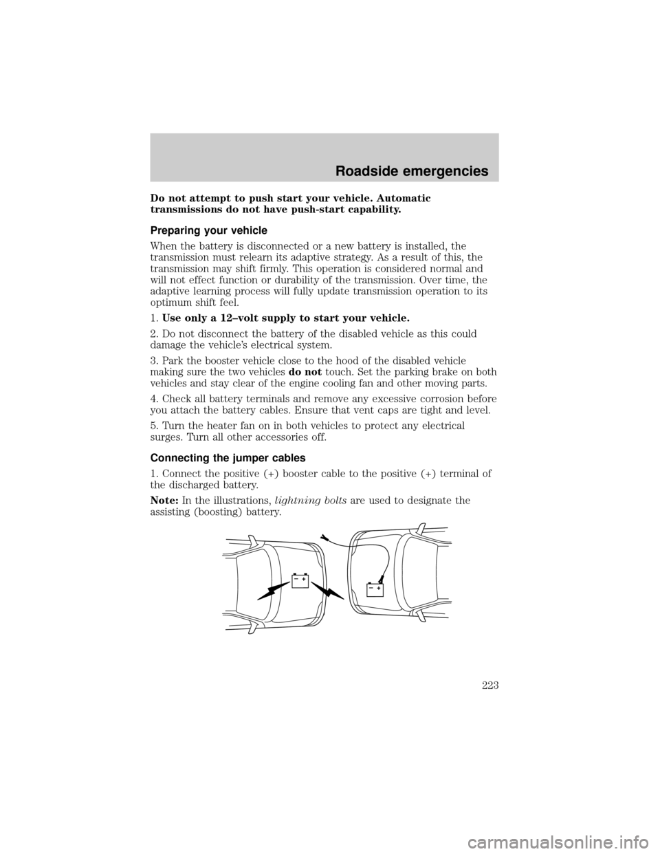
Connecting the jumper cables
1. Connect the positive (+) booster cable to the positive (+) terminal of
the discharged battery.
Note:In the illustrations,lightning boltsare used to designate the
assisting (boosting) battery.
+–+–
Roadside emergencies
223