Page 3 of 280
Maintenance and specifications 225
Hood 226
Engine compartment 227
Engine oil 228
Battery 231
Fuel information 240
Air filter(s) 254
Part numbers 259
Refill capacities 260
Lubricant specifications 263
Engine data 265
Vehicle dimensions 266
Accessories 269
Index 273
All rights reserved. Reproduction by any means, electronic or mechanical
including photocopying, recording or by any information storage and retrieval
system or translation in whole or part is not permitted without written
authorization from Ford Motor Company. Ford may change the contents without
notice and without incurring obligation.
Copyright 2001 Ford Motor Company
Table of contents
3
Page 9 of 280
Vehicle Symbol Glossary
Child Safety Door
Lock/Unlock
Interior Luggage
Compartment Release
Symbol
Panic AlarmEngine Oil
Engine CoolantEngine Coolant
Temperature
Do Not Open When HotBattery
Avoid Smoking, Flames,
or SparksBattery Acid
Explosive GasFan Warning
Power Steering FluidMaintain Correct Fluid
LevelMAX
MIN
Emission SystemEngine Air Filter
Passenger Compartment
Air FilterJack
Check fuel capLow tire warning
Introduction
9
Page 12 of 280
Air bag readiness
Illuminates to confirm that the air
bags (front or side) are operational.
If the light fails to illuminate,
continues to flash or remains on,
have the system serviced immediately.
Charging system
Illuminates when the battery is not
charging properly.
Check air suspension
Illuminates momentarily when the
ignition is turned to the ON position
and the engine is OFF. The light also
illuminates when the air suspension
switch is turned OFF or the air suspension system requires servicing.
For information on the air suspension system, refer to theDriving
chapter.
Low fuel
Illuminates when the fuel level in
the fuel tank is at, or near, empty
(refer toFuel gaugein this chapter
for more information).
Low washer fluid
Illuminates when the windshield
washer fluid is low.
Speed control
Illuminates when the speed control
is activated.
CK
SUSP
LOW
FUEL
Instrument cluster
12
Page 16 of 280
Battery voltage gauge
Indicates battery voltage. If the
pointer moves and stays outside the
normal operating range (as
indicated by the arrows), have the
vehicle's electrical system checked
as soon as possible.
Fuel gauge
Displays approximately how much
fuel is in the fuel tank. The fuel
gauge may vary slightly when the
vehicle is in motion or on a grade.
When refueling the vehicle from
empty indication, the amount of fuel
that can be added will be less than
the advertised capacity due to the
reserve fuel.
A minimum of 22.2 L (six gallons)
must be added or removed from the fuel tank in order for the gauge to
instantaneously update. If less than six gallons is the change, the gauge
will take between five to twenty minutes to update.
Speedometer
Indicates the current vehicle speed.
E
F
FUEL DOOR
0
MPHkm/h
20406080
00
20
40
60
Instrument cluster
16
Page 98 of 280

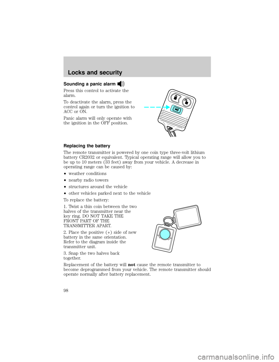
Sounding a panic alarm
Press this control to activate the
alarm.
To deactivate the alarm, press the
control again or turn the ignition to
ACC or ON.
Panic alarm will only operate with
the ignition in the OFF position.
Replacing the battery
The remote transmitter is powered by one coin type three-volt lithium
battery CR2032 or equivalent. Typical operating range will allow you to
be up to 10 meters (33 feet) away from your vehicle. A decrease in
operating range can be caused by:
²weather conditions
²nearby radio towers
²structures around the vehicle
²other vehicles parked next to the vehicle
To replace the battery:
1. Twist a thin coin between the two
halves of the transmitter near the
key ring. DO NOT TAKE THE
FRONT PART OF THE
TRANSMITTER APART.
2. Place the positive (+) side of new
battery in the same orientation.
Refer to the diagram inside the
transmitter unit.
3. Snap the two halves back
together.
Replacement of the battery willnotcause the remote transmitter to
become deprogrammed from your vehicle. The remote transmitter should
operate normally after battery replacement.
Locks and security
98
Page 100 of 280

Illuminated entry
The illuminated entry system will turn on the interior lights when the
remote transmitter unlock control is pressed.
The illuminated entry system will turn off the interior lights if the
ignition switch is turned to the ON position, or if the remote transmitter
lock control is pressed, or after 25 seconds of illumination.
The inside lights will not turn off if:
²they have been turned on with the dimmer control or
²any door is open
The battery save feature will turn off the interior lights 45 minutes after
the last door is closed, even if the dimmer control is on.
Memory seat/mirrors/adjustable pedal feature (if equipped)
The memory feature allows automatic positioning of the driver seat, side
mirrors and adjustable pedals to three programmable positions.
²To program position one, move the driver seat, both side mirrors, and
adjustable pedals to the desired positions. Press the SET control. The
SET control indicator light will briefly illuminate. While the light is
illuminated, press control 1.
²To program position two, repeat the previous procedure using control
2.
²To program position three, repeat the previous procedure but press
controls 1 and 2 simultaneously.
The memory feature also allows you to recall previously stored positions
with your remote transmitter(s). Up to three remote transmitters can be
activated to utilize the memory recall positions.
Press the memory feature control to move to the previously stored
seat/mirror/adjustable pedal positions.
Activating/deactivating the memory feature on your remote
transmitter
The memory feature from the remote transmitter can be turned off/on,
however, the memory control buttons will continue to operate. Before
following the procedure, make sure that the ignition is OFF and all doors
and the liftgate window are closed. You must complete steps 1±7 within
30 seconds or the procedure will have to be repeated. If the procedure
needs to be repeated, you must wait 30 seconds.
Locks and security
100
Page 164 of 280

Each time the vehicle is started, the transmission will automatically
return to normal overdrive mode.
Every time the vehicle is shut off and restarted, you must press the
transmission control switch to cancel overdrive operation if driving in
overdrive is not desired.
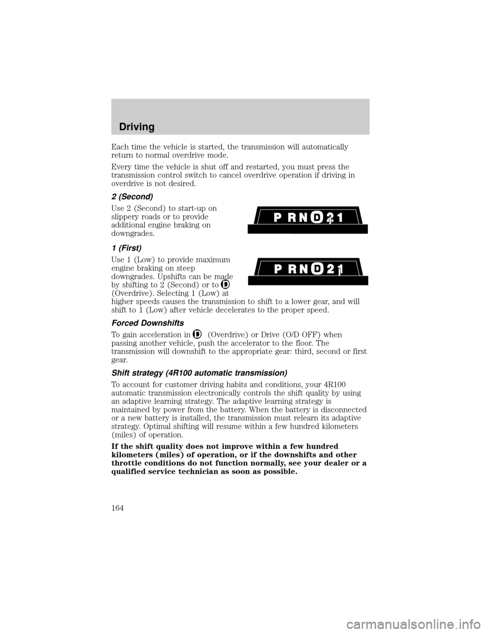
2 (Second)
Use 2 (Second) to start-up on
slippery roads or to provide
additional engine braking on
downgrades.
1 (First)
Use 1 (Low) to provide maximum
engine braking on steep
downgrades. Upshifts can be made
by shifting to 2 (Second) or to
(Overdrive). Selecting 1 (Low) at
higher speeds causes the transmission to shift to a lower gear, and will
shift to 1 (Low) after vehicle decelerates to the proper speed.
Forced Downshifts
To gain acceleration in(Overdrive) or Drive (O/D OFF) when
passing another vehicle, push the accelerator to the floor. The
transmission will downshift to the appropriate gear: third, second or first
gear.
Shift strategy (4R100 automatic transmission)
To account for customer driving habits and conditions, your 4R100
automatic transmission electronically controls the shift quality by using
an adaptive learning strategy. The adaptive learning strategy is
maintained by power from the battery. When the battery is disconnected
or a new battery is installed, the transmission must relearn its adaptive
strategy. Optimal shifting will resume within a few hundred kilometers
(miles) of operation.
If the shift quality does not improve within a few hundred
kilometers (miles) of operation, or if the downshifts and other
throttle conditions do not function normally, see your dealer or a
qualified service technician as soon as possible.
Driving
164
Page 180 of 280

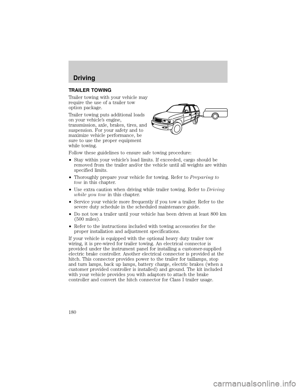
TRAILER TOWING
Trailer towing with your vehicle may
require the use of a trailer tow
option package.
Trailer towing puts additional loads
on your vehicle's engine,
transmission, axle, brakes, tires, and
suspension. For your safety and to
maximize vehicle performance, be
sure to use the proper equipment
while towing.
Follow these guidelines to ensure safe towing procedure:
²Stay within your vehicle's load limits. If exceeded, cargo should be
removed from the trailer and/or the vehicle until all weights are within
specified limits.
²Thoroughly prepare your vehicle for towing. Refer toPreparing to
towin this chapter.
²Use extra caution when driving while trailer towing. Refer toDriving
while you towin this chapter.
²Service your vehicle more frequently if you tow a trailer. Refer to the
severe duty schedule in the scheduled maintenance guide.
²Do not tow a trailer until your vehicle has been driven at least 800 km
(500 miles).
²Refer to the instructions included with towing accessories for the
proper installation and adjustment specifications.
If your vehicle is equipped with the optional heavy duty trailer tow
wiring, it is pre-wired for trailer towing. An electrical connector is
provided under the instrument panel for installing a customer-supplied
electric brake controller. Another electrical connector is provided at the
hitch. This connector provides power to the trailer for taillamps, stop
and turn lamps, back up lamps, battery charge, electric brakes (when a
customer provided controller is installed) and ground. The kit included
with your vehicle provides you with adaptors to attach the brake
controller and convert the hitch connector for Class I trailer usage.
Driving
180