Page 148 of 256

1 (First)
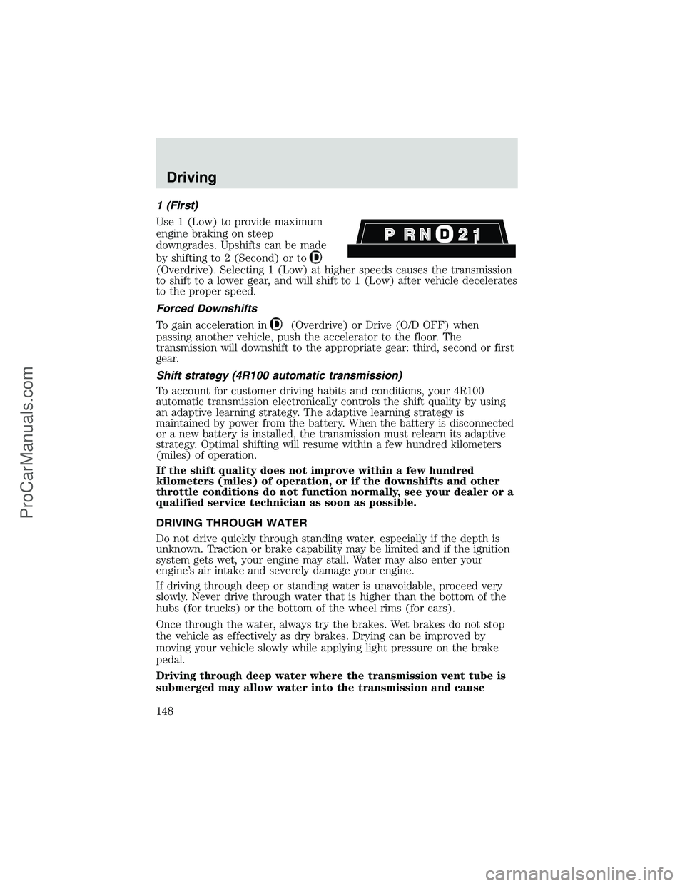
Use 1 (Low) to provide maximum
engine braking on steep
downgrades. Upshifts can be made
by shifting to 2 (Second) or to
(Overdrive). Selecting 1 (Low) at higher speeds causes the transmission
to shift to a lower gear, and will shift to 1 (Low) after vehicle decelerates
to the proper speed.
Forced Downshifts
To gain acceleration in
(Overdrive) or Drive (O/D OFF) when
passing another vehicle, push the accelerator to the floor. The
transmission will downshift to the appropriate gear: third, second or first
gear.
Shift strategy (4R100 automatic transmission)
To account for customer driving habits and conditions, your 4R100
automatic transmission electronically controls the shift quality by using
an adaptive learning strategy. The adaptive learning strategy is
maintained by power from the battery. When the battery is disconnected
or a new battery is installed, the transmission must relearn its adaptive
strategy. Optimal shifting will resume within a few hundred kilometers
(miles) of operation.
If the shift quality does not improve within a few hundred
kilometers (miles) of operation, or if the downshifts and other
throttle conditions do not function normally, see your dealer or a
qualified service technician as soon as possible.
DRIVING THROUGH WATER
Do not drive quickly through standing water, especially if the depth is
unknown. Traction or brake capability may be limited and if the ignition
system gets wet, your engine may stall. Water may also enter your
engine’s air intake and severely damage your engine.
If driving through deep or standing water is unavoidable, proceed very
slowly. Never drive through water that is higher than the bottom of the
hubs (for trucks) or the bottom of the wheel rims (for cars).
Once through the water, always try the brakes. Wet brakes do not stop
the vehicle as effectively as dry brakes. Drying can be improved by
moving your vehicle slowly while applying light pressure on the brake
pedal.
Driving through deep water where the transmission vent tube is
submerged may allow water into the transmission and cause
Driving
148
ProCarManuals.com
Page 159 of 256

Canadian customers who require roadside assistance, call
1–800–665–2006.
If you need to arrange roadside assistance for yourself, Ford Motor
Company will reimburse a reasonable amount. To obtain reimbursement
information, U.S. Ford or Mercury vehicles customers call
1-800-241-3673; Lincoln vehicle customers call 1–800–521–4140.
Canadian customers who need to obtain reimbursement information, call
1–800–665–2006.
ROADSIDE COVERAGE BEYOND BASIC WARRANTY
In the United States, you may purchase additional roadside assistance
coverage beyond this period through the Ford Auto Club by contacting
your Ford or Lincoln Mercury dealer.
Similarly in Canada, for uninterrupted Roadside Assistance coverage, you
may purchase extended coverage prior to your Basic Warranty’s Roadside
Assistance expiring. For more information and enrollment, contact
1–877–294–2582 or visit our website at www.ford.ca.
HAZARD FLASHER
Use only in an emergency to warn traffic of vehicle breakdown,
approaching danger, etc. The hazard flashers can be operated when the
ignition is off.
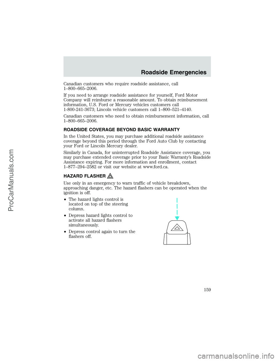
•The hazard lights control is
located on top of the steering
column.
•Depress hazard lights control to
activate all hazard flashers
simultaneously.
•Depress control again to turn the
flashers off.
Roadside Emergencies
159
ProCarManuals.com
Page 163 of 256
The fuses are coded as follows.
Fuse/Relay
LocationFuse Amp
RatingPassenger Compartment Fuse
Panel Description
1 20A 4WABS module
2 15A Brake warning lamp, Instrument
cluster, Warning chime, 4WABS
relay, Warning indicators, Low
vacuum warning switch (Diesel
only)
3 15A Main light switch, RKE module,
Radio, Instrument illumination,
E-Traveler VCP and video
screens, Overhead console
4 15A Power locks w/RKE, Illuminated
entry, Warning chime, Modified
vehicle, Main light switch,
Courtesy lamps
1234
5
7
689101142
43
44 13 12 14
15 16 17
19 18
2021 22 23
25 24
26 27 28 29
31 30 32 33 3435
37
3638 3940
41
Roadside Emergencies
163
ProCarManuals.com
Page 164 of 256

Fuse/Relay
LocationFuse Amp
RatingPassenger Compartment Fuse
Panel Description
5 20A RKE module, Power lock
switches, Memory lock, Power
locks with RKE
6 10A Brake shift interlock, Speed
control, DRL module
7 10A Multi-function switch, Turn signals
8 30A Radio capacitor(s), Ignition coil,
PCM diode, PCM power relay,
Fuel heater (Diesel only), Glow
plug relay (Diesel only)
9 30A Wiper control module, Windshield
wiper motor
10 20A Main light switch, Park lamps,
License lamp (external lamps),
Multi-function switch
(flash-to-pass)
11 15A Brake pressure switch,
Multi-function switch (hazards),
Brake lamp switch, Brake lamps
12 15A Transmission Range (TR) sensor,
Backup lamps, Auxiliary battery
relay
13 15A Blend door actuator, A/C heater,
Function selector switch
14 5A Instrument cluster (air bag and
charge indicator)
15 5A Trailer battery charge relay
16 30A Power seats
17—Not used
18—Not used
19 10A Air bag diagnostic monitor
20 5A Overdrive cancel switch
21 30A Power windows*
22 15A Memory power radio, E-Traveler
radio, E-Traveler console
Roadside Emergencies
164
ProCarManuals.com
Page 165 of 256

Fuse/Relay
LocationFuse Amp
RatingPassenger Compartment Fuse
Panel Description
23 20A Cigar lighter, Data Link Connector
(DLC)
24—Not used
25 10A Left headlamp (low beam)
26—Not used
27 5A Radio
28 20A Power plug
29—Not used
30 15A Headlamps (high beam indicator),
DRL10A
31 10A Right Headlamp (Low Beam),
DRL
32 5A Power mirrors
33 20A E-Traveler power point #2
34 10A Transmission Range (TR) sensor
35 30A RKE module
36 5A (Cluster, A/C, Illumination,
Radio), Steering column assembly
37 20A Rear power point
38 10A Air bag diagnostic monitor
39 20A E-Traveler power point #1
40 30A Modified vehicle
41 30A Modified vehicle
42—Not used
43 20A C.B. Power windows*
44—Not used
* Either Fuse 21 or Circuit breaker 43 will be present for power
windows.
Power distribution box
The power distribution box is located in the engine compartment. The
power distribution box contains high-current fuses that protect your
vehicle’s main electrical systems from overloads.
Roadside Emergencies
165
ProCarManuals.com
Page 167 of 256

Fuse/Relay
LocationFuse Amp
RatingPower Distribution Box
Description
8 60A** I/P fuses 4, 5, 10, 11, 16, 22, 23,
28, 32, 38
9 30A** PCM power relay, Engine
compartment fuse 4
10 60A** Auxiliary battery relay, Engine
compartment fuses 14, 22
11 30A** IDM relay (Diesel only)
12 60A** Engine compartment fuses 25, 27
13 50A** Blower motor relay (blower
motor)
14 30A** Trailer running lamps relay,
Trailer backup lamps relay
15 40A** Main light switch, Daytime
Running Lights (DRL)
16 50A** Auxiliary blower motor relay
17 30A** Fuel pump relay
18 60A** I/P fuses 33, 37, 39, 40, 41
19 60A** 4WABS module
20 20A** Electric brake controller
21 50A** Modified vehicle power
22 40A** Trailer battery charge relay,
Modified vehicles
23 60A** Ignition switch, Fuse panel
24 30A* Natural gas tank valves (NGV
only)
25 20A* NGV module (NGV only)
26 10A* A/C clutch (4.2L only)
27 15A* DRL module, Horn relay
28—PCM diode
29—Not used
A—Marker lamps relay
B—Stop lamp relay
Roadside Emergencies
167
ProCarManuals.com
Page 176 of 256
3. Park the booster vehicle close to the hood of the disabled vehicle
making sure the two vehiclesdo nottouch. Set the parking brake on
both vehicles and stay clear of the engine cooling fan and other moving
parts.
4. Check all battery terminals and remove any excessive corrosion before
you attach the battery cables. Ensure that vent caps are tight and level.
5. Turn the heater fan on in both vehicles to protect any electrical
surges. Turn all other accessories off.
Connecting the jumper cables
1. Connect the positive (+) booster cable to the positive (+) terminal of
the discharged battery.
Note:In the illustrations,lightning boltsare used to designate the
assisting (boosting) battery.
2. Connect the other end of the positive (+) cable to the positive (+)
terminal of the assisting battery.
+–+–
+–+–
Roadside Emergencies
176
ProCarManuals.com
Page 178 of 256
Removing the jumper cables
Remove the jumper cables in the reverse order that they were
connected.
1. Remove the jumper cable from thegroundmetal surface.
Note:In the illustrations,lightning boltsare used to designate the
assisting (boosting) battery.
2. Remove the jumper cable on the negative (-) connection of the
booster vehicle’s battery.
+–+–
+–+–
Roadside Emergencies
178
ProCarManuals.com