Page 151 of 240

Once through the water, always try the brakes. Wet brakes do not stop the
vehicle as effectively as dry brakes. Drying can be improved by moving
your vehicle slowly while applying light pressure on the brake pedal.
Driving through deep water where the transmission vent tube is
submerged may allow water into the transmission and cause
internal transmission damage. Have the fluid checked and, if
water is found, replace the fluid.
VEHICLE LOADING
Before loading a vehicle, familiarize yourself with the following terms:
²Base Curb Weight:Weight of the vehicle including any standard
equipment, fluids, lubricants, etc. It does not include occupants or
aftermarket equipment.
²Payload:Combined maximum allowable weight of cargo, occupants
and optional equipment. The payload equals the gross vehicle weight
rating minus base curb weight.
²GVW (Gross Vehicle Weight):Base curb weight plus payload
weight. The GVW is not a limit or a specification.
²GVWR (Gross Vehicle Weight Rating):Maximum permissible total
weight of the base vehicle, occupants, optional equipment and cargo.
The GVWR is specific to each vehicle and is listed on the Safety
Certification Label on the driver's door pillar.
²GAWR (Gross Axle Weight Rating):Carrying capacity for each axle
system. The GAWR is specific to each vehicle and is listed on the
Safety Certification Label on the driver's door pillar.
²GCW (Gross Combined Weight):The combined weight of the
towing vehicle (including occupants and cargo) and the loaded trailer.
²GCWR (Gross Combined Weight Rating):Maximum permissible
combined weight of the towing vehicle (including occupants and
cargo) and the loaded trailer.
²Maximum Trailer Weight Rating:Maximum weight of a trailer the
vehicle is permitted to tow. The maximum trailer weight rating is
determined by subtracting the vehicle curb weight for each
engine/transmission combination, any required option weight for trailer
towing and the weight of the driver from the GCWR for the towing
vehicle.
²Maximum Trailer Weight:Maximum weight of a trailer the loaded
vehicle (including occupants and cargo) is permitted to tow. It is
determined by subtracting the weight of the loaded trailer towing
vehicle from the GCWR for the towing vehicle.
Driving
151
Page 152 of 240

²Trailer Weight Range:Specified weight range that the trailer must
fall within that ranges from zero to the maximum trailer weight rating.
Remember to figure in the tongue load of your loaded trailer when
figuring the total weight.
Do not exceed the GVWR or the GAWR specified on the
certification label.
Do not use replacement tires with lower load carrying capacities than the
originals because they may lower the vehicle's GVWR and GAWR
limitations. Replacement tires with a higher limit than the originals do
not increase the GVWR and GAWR limitations.
The Certification Label, found on the inside pillar of the driver's door,
lists several important vehicle weight rating limitations. Before adding
any additional equipment, refer to these limitations. If you are adding
weight to your vehicle, always ensure that the weight of occupants, cargo
and equipment being carried is within the weight limitations that have
been established for your vehicle including both gross vehicle weight and
front and rear gross axle weight rating limits. Under no circumstance
should these limitations be exceeded.
Never exceed the GVWR specified on the certification label as
this could result in serious damage to the vehicle and/or personal
injury.
The weight of your loaded trailer should not exceed 907 kg (2 000 lbs).
The GCW of your vehicle and trailer should not exceed 2 993 kg
(6 600 lbs).
TRAILER TOWING
Your vehicle is classified as a light duty towing vehicle. Do not tow a
trailer until your vehicle has been driven at least 3,200 km (2,000 miles).
Towing a trailer places an additional load on your vehicle's engine,
transmission, brakes, tires and suspension. Inspect these components
carefully after towing.
Your loaded trailer should weigh no more than 907 kg (2,000 lbs.).Do
not exceed the GVWR specified on the certification label.
Towing trailers beyond the maximum recommended gross trailer
weight could result in engine damage, transmission/axle damage,
structural damage, loss of control, and personal injury.
Driving
152
Page 157 of 240

U.S. Ford or Mercury vehicle customers who require roadside assistance,
call 1±800±241±3673; Lincoln vehicle customers call 1±800±521±4140.
Canadian customers who require roadside assistance, call
1±800±665±2006.
If you need to arrange roadside assistance for yourself, Ford Motor
Company will reimburse a reasonable amount. To obtain reimbursement
information, U.S. Ford or Mercury vehicles customers call
1-800-241-3673; Lincoln vehicle customers call 1±800±521±4140.
Canadian customers who need to obtain reimbursement information, call
1±800±665±2006.
ROADSIDE COVERAGE BEYOND BASIC WARRANTY
In the United States, you may purchase additional roadside assistance
coverage beyond this period through the Ford Auto Club by contacting
your Ford or Lincoln Mercury dealer.
Similarly in Canada, for uninterrupted Roadside Assistance coverage, you
may purchase extended coverage prior to your Basic Warranty's Roadside
Assistance expiring. For more information and enrollment, contact
1±877±294±2582 or visit our website at www.ford.ca.
HAZARD FLASHER
Use only in an emergency to warn traffic of vehicle breakdown,
approaching danger, etc. The hazard flashers can be operated when the
ignition is off.
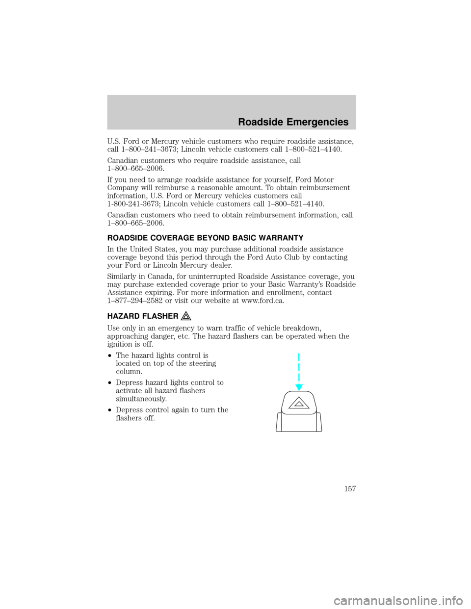
²The hazard lights control is
located on top of the steering
column.
²Depress hazard lights control to
activate all hazard flashers
simultaneously.
²Depress control again to turn the
flashers off.
Roadside Emergencies
157
Page 158 of 240
FUEL PUMP SHUT-OFF SWITCHFUEL
RESET
The fuel pump shut-off switch is a device intended to stop the electric
fuel pump when your vehicle has been involved in a substantial jolt.
After a collision, if the engine cranks but does not start, the fuel pump
shut-off switch may have been activated.
The fuel pump shut-off switch is
located on the left side of the trunk
behind the left rear tail light and the
trunk liner.
Use the following procedure to reset the fuel pump shut-off switch.
1. Turn the ignition to the OFF position.
2. Check the fuel system for leaks.
3. If no fuel leak is apparent, reset the fuel pump shut-off switch by
pushing in on the reset button.
4. Turn the ignition to the ON position. Pause for a few seconds and
return the key to the OFF position.
5. Make a further check for leaks in the fuel system.
Roadside Emergencies
158
Page 160 of 240
Passenger compartment fuse panel
The fuse panel is located below and to the left of the steering wheel by
the brake pedal. Remove the panel cover to access the fuses.
To remove a fuse use the fuse puller tool provided on the fuse panel
cover.
The fuses are coded as follows.
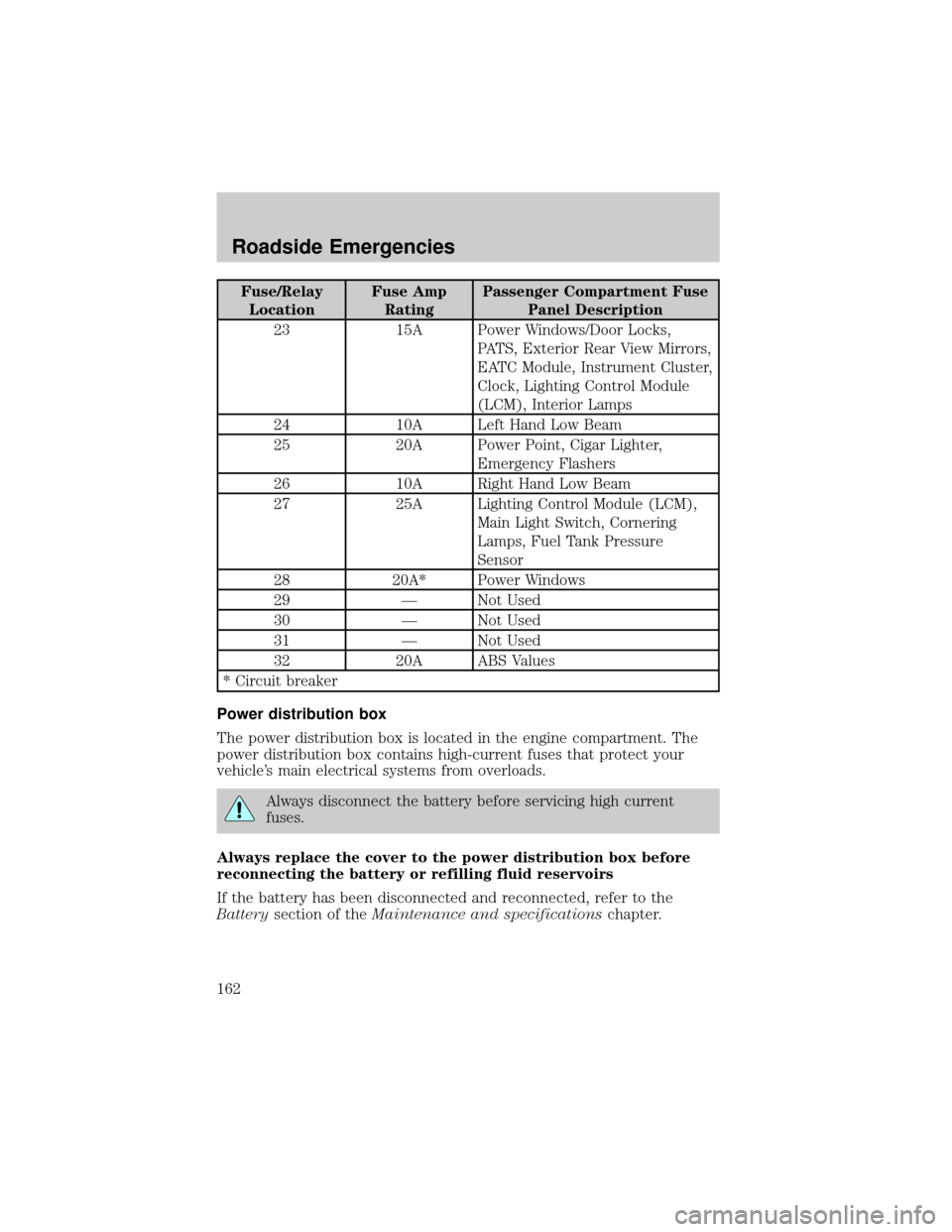
Fuse/Relay
LocationFuse Amp
RatingPassenger Compartment Fuse
Panel Description
1 Ð Not Used
2 Ð Not Used
3 Ð Not Used
4 10A Air Bags
5 Ð Not Used
6 15A Instrument Cluster, Warning
Lamps Module, Transmission
Control Switch, Lighting Control
Module (LCM)
7 Ð Not Used
27 25
26 2423 21
2219
20
18 16
17 1514 12
131030
32
31
28
29
11
97
8653
41
2
Roadside Emergencies
160
Page 161 of 240
Fuse/Relay
LocationFuse Amp
RatingPassenger Compartment Fuse
Panel Description
8 25A Power Train Control Module
(PCM) Power Relay, Coil-on
-Plugs, Radio Noise Capacitor,
Passive Anti-theft System (PATS)
9 Ð Not Used
10 10A Rear Window Defrost
11 Ð Not Used
12 Ð Not Used
13 5A Radio
14 10A Traction Control Switch, Anti-lock
Brakes (ABS), Instrument Cluster
15 15A Speed Control Servo, Main Light
Switch Illumination, Lighting
Control Module (LCM), Clock,
Police Power Relay
16 15A Reversing lamps, Turn Signals,
Shift Lock, DRL Module, EVO
Steering, Electronic Day/Night
Mirror
17 30A Wiper Motor, Wiper Control
Module
18 30A Heater Blower Motor
19 20A Auxiliary Power Point
20 Ð Not Used
21 15A Multifunction Switch, Lighting
Control Module (LCM), PATS
Indicator, Parking Lamps,
Instrument Panel Light
22 15A Speed Control Servo, Hazard
Lights
Roadside Emergencies
161
Page 162 of 240

Fuse/Relay
LocationFuse Amp
RatingPassenger Compartment Fuse
Panel Description
23 15A Power Windows/Door Locks,
PATS, Exterior Rear View Mirrors,
EATC Module, Instrument Cluster,
Clock, Lighting Control Module
(LCM), Interior Lamps
24 10A Left Hand Low Beam
25 20A Power Point, Cigar Lighter,
Emergency Flashers
26 10A Right Hand Low Beam
27 25A Lighting Control Module (LCM),
Main Light Switch, Cornering
Lamps, Fuel Tank Pressure
Sensor
28 20A* Power Windows
29 Ð Not Used
30 Ð Not Used
31 Ð Not Used
32 20A ABS Values
* Circuit breaker
Power distribution box
The power distribution box is located in the engine compartment. The
power distribution box contains high-current fuses that protect your
vehicle's main electrical systems from overloads.
Always disconnect the battery before servicing high current
fuses.
Always replace the cover to the power distribution box before
reconnecting the battery or refilling fluid reservoirs
If the battery has been disconnected and reconnected, refer to the
Batterysection of theMaintenance and specificationschapter.
Roadside Emergencies
162
Page 170 of 240
Connecting the jumper cables
1. Connect the positive (+) booster cable to the positive (+) terminal of
the discharged battery.
Note:In the illustrations,lightning boltsare used to designate the
assisting (boosting) battery.
2. Connect the other end of the positive (+) cable to the positive (+)
terminal of the assisting battery.
+–+–
+–+–
Roadside Emergencies
170