2002 DODGE TOWN AND COUNTRY cooling system
[x] Cancel search: cooling systemPage 1 of 2399

GROUP TAB LOCATOR
INIntroduction
0Lubrication & Maintenance
2Suspension
3Differential & Driveline
5Brakes
6Clutch
7Cooling
7aCooling - 2.5L Turbo Diesel
8AAudio
8BChime/Buzzer
8EElectronic Control Modules
8EaElectronic Control Modules
8FEngine Systems
8FaEngine Systems
8GHeated Systems
8HHorn
8IIgnition Control
8IaIgnition Control
8JInstrument Cluster
8LLamps
8MMessage Systems
8NPower Systems
8ORestraints
8PSpeed Control
8QVehicle Theft Security
8RWipers/Washers
8WWiring
9Engine
9aEngine
11Exhaust System
11aExhaust System and Turbocharger
13Frame & Bumpers
14Fuel System
14aFuel System
19Steering
21Transmission
22Tires/Wheels
23Body
24Heating & Air Conditioning
25Emissions Control
25aEmissions Control 2.5L Turbo Diesel
Service Manual Comment Forms
ProCarManuals.com
Page 14 of 2399
LUBRICATION & MAINTENANCE
TABLE OF CONTENTS
page page
LUBRICATION & MAINTENANCE
SPECIFICATIONS - FLUID CAPACITIES.......1
INTERNATIONAL SYMBOLS
DESCRIPTION..........................2
FLUID TYPES
DESCRIPTION
DESCRIPTION - ENGINE OIL AND
LUBRICANTS.........................2
DESCRIPTION - ENGINE COOLANT........3
DESCRIPTION - FLEXIBLE FUEL ENGINE
OIL .................................3
DESCRIPTION - AUTOMATIC
TRANSMISSION FLUID..................4
DESCRIPTION - FUEL REQUIREMENTS.....4
DESCRIPTION - FUEL REQUIREMENTS -
DIESEL ENGINE.......................6DESCRIPTION - ENGINE OIL - DIESEL
ENGINES............................6
FLUID FILL/CHECK LOCATIONS
DESCRIPTION..........................6
LUBRICATION POINTS
DESCRIPTION..........................6
MAINTENANCE SCHEDULES
DESCRIPTION..........................6
HOISTING
STANDARD PROCEDURE - HOISTING........6
JUMP STARTING
STANDARD PROCEDURE - JUMP STARTING . . 7
TOWING
STANDARD PROCEDURE - TOWING.........8
LUBRICATION &
MAINTENANCE
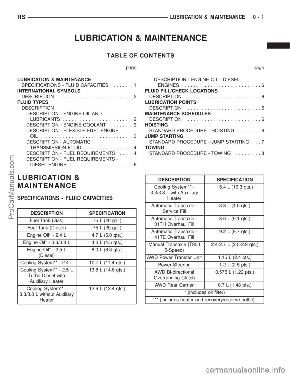
SPECIFICATIONS - FLUID CAPACITIES
DESCRIPTION SPECIFICATION
Fuel Tank (Gas) 75 L (20 gal.)
Fuel Tank (Diesel) 75 L (20 gal.)
Engine Oil* - 2.4 L 4.7 L (5.0 qts.)
Engine Oil* - 3.3/3.8 L 4.0 L (4.5 qts.)
Engine Oil* - 2.5 L
(Diesel)6.0 L (6.3 qts.)
Cooling System** - 2.4 L 10.7 L (11.4 qts.)
Cooling System** - 2.5 L
Turbo Diesel with
Auxiliary Heater13.8 L (14.6 qts.)
Cooling System** -
3.3/3.8 L without Auxiliary
Heater12.6 L (13.4 qts.)
DESCRIPTION SPECIFICATION
Cooling System** -
3.3/3.8 L with Auxiliary
Heater15.4 L (16.3 qts.)
Automatic Transaxle -
Service Fill3.8 L (4.0 qts.)
Automatic Transaxle -
31TH Overhaul Fill8.6 L (9.1 qts.)
Automatic Transaxle -
41TE Overhaul Fill9.2 L (9.7 qts.)
Manual Transaxle (T850
5-Speed)2.4-2.7 L (2.5-2.9 qts.)
AWD Power Transfer Unit 1.15 L (2.4 pts.)
Power Steering 1.2 L (2.5 pts.)
AWD Bi-directional
Overrunning Clutch0.575 L (1.22 pts.)
AWD Rear Carrier 0.7 L (1.48 pts.)
* (includes oil filter)
** (includes heater and recovery/reserve bottle)
RSLUBRICATION & MAINTENANCE0-1
ProCarManuals.com
Page 16 of 2399
GEAR LUBRICANTS
SAE ratings also apply to multigrade gear lubri-
cants. In addition, API classification defines the
lubricants usage. Such as API GL-5 and SAE 75W-
90.
LUBRICANTS AND GREASES
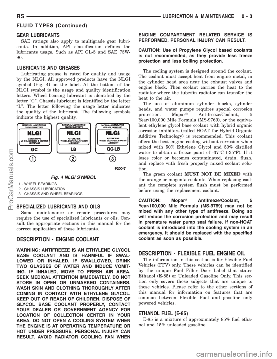
Lubricating grease is rated for quality and usage
by the NLGI. All approved products have the NLGI
symbol (Fig. 4) on the label. At the bottom of the
NLGI symbol is the usage and quality identification
letters. Wheel bearing lubricant is identified by the
letter ªGº. Chassis lubricant is identified by the letter
ªLº. The letter following the usage letter indicates
the quality of the lubricant. The following symbols
indicate the highest quality.
SPECIALIZED LUBRICANTS AND OILS
Some maintenance or repair procedures may
require the use of specialized lubricants or oils. Con-
sult the appropriate sections in this manual for the
correct application of these lubricants.
DESCRIPTION - ENGINE COOLANT
WARNING: ANTIFREEZE IS AN ETHYLENE GLYCOL
BASE COOLANT AND IS HARMFUL IF SWAL-
LOWED OR INHALED. IF SWALLOWED, DRINK
TWO GLASSES OF WATER AND INDUCE VOMIT-
ING. IF INHALED, MOVE TO FRESH AIR AREA.
SEEK MEDICAL ATTENTION IMMEDIATELY. DO NOT
STORE IN OPEN OR UNMARKED CONTAINERS.
WASH SKIN AND CLOTHING THOROUGHLY AFTER
COMING IN CONTACT WITH ETHYLENE GLYCOL.
KEEP OUT OF REACH OF CHILDREN. DISPOSE OF
GLYCOL BASE COOLANT PROPERLY, CONTACT
YOUR DEALER OR GOVERNMENT AGENCY FOR
LOCATION OF COLLECTION CENTER IN YOUR
AREA. DO NOT OPEN A COOLING SYSTEM WHEN
THE ENGINE IS AT OPERATING TEMPERATURE OR
HOT UNDER PRESSURE, PERSONAL INJURY CAN
RESULT. AVOID RADIATOR COOLING FAN WHENENGINE COMPARTMENT RELATED SERVICE IS
PERFORMED, PERSONAL INJURY CAN RESULT.
CAUTION: Use of Propylene Glycol based coolants
is not recommended, as they provide less freeze
protection and less boiling protection.
The cooling system is designed around the coolant.
The coolant must accept heat from engine metal, in
the cylinder head area near the exhaust valves and
engine block. Then coolant carries the heat to the
radiator where the tube/fin radiator can transfer the
heat to the air.
The use of aluminum cylinder blocks, cylinder
heads, and water pumps requires special corrosion
protection. MopartAntifreeze/Coolant, 5
Year/100,000 Mile Formula (MS-9769), or the equiva-
lent ethylene glycol base coolant with hybrid organic
corrosion inhibitors (called HOAT, for Hybrid Organic
Additive Technology) is recommended. This coolant
offers the best engine cooling without corrosion when
mixed with 50% Ethylene Glycol and 50% distilled
water to obtain a freeze point of -37ÉC (-35ÉF). If it
loses color or becomes contaminated, drain, flush,
and replace with fresh properly mixed coolant solu-
tion.
The green coolantMUST NOT BE MIXEDwith
the orange or magenta coolants. When replacing cool-
ant the complete system flush must be performed
before using the replacement coolant.
CAUTION: MoparTAntifreeze/Coolant, 5
Year/100,000 Mile Formula (MS-9769) may not be
mixed with any other type of antifreeze. Doing so
will reduce the corrosion protection and may result
in premature water pump seal failure. If non-HOAT
coolant is introduced into the cooling system in an
emergency, it should be replaced with the specified
coolant as soon as possible.DESCRIPTION - FLEXIBLE FUEL ENGINE OIL
The information in this section is for Flexible Fuel
Vehicles (FFV) only. These vehicles can be identified
by the unique Fuel Filler Door Label that states
Ethanol (E-85) or Unleaded Gasoline Only. This sec-
tion only covers those subjects that are unique to
these vehicles. Please refer to the other sections of
this manual for information on features that are
common between Flexible Fuel and gasoline only
powered vehicles.
ETHANOL FUEL (E-85)
E-85 is a mixture of approximately 85% fuel etha-
nol and 15% unleaded gasoline.
Fig. 4 NLGI SYMBOL
1 - WHEEL BEARINGS
2 - CHASSIS LUBRICATION
3 - CHASSIS AND WHEEL BEARINGS
RSLUBRICATION & MAINTENANCE0-3
FLUID TYPES (Continued)
ProCarManuals.com
Page 250 of 2399

COOLING
TABLE OF CONTENTS
page page
COOLING
DESCRIPTION
DESCRIPTION - COOLING SYSTEM........1
DESCRIPTION - HOSE CLAMPS...........1
OPERATION
OPERATION - COOLING SYSTEM.........2
OPERATION - HOSE CLAMPS............2
DIAGNOSIS AND TESTING
DIAGNOSIS AND TESTING - COOLING
SYSTEM LEAK TEST....................2
DIAGNOSIS AND TESTING - COOLING
SYSTEM FLOW CHECK.................3
DIAGNOSIS AND TESTING - COOLING
SYSTEM AERATION....................4
DIAGNOSIS AND TESTING - COOLING
SYSTEM DEAERATION..................4
STANDARD PROCEDURE
STANDARD PROCEDURE - COOLING
SYSTEM DRAINING....................4STANDARD PROCEDURE - COOLING
SYSTEM FILLING......................4
STANDARD PROCEDURE - ADDING
ADDITIONAL COOLANT.................4
STANDARD PROCEDURE - COOLANT
LEVEL CHECK........................5
SPECIFICATIONS
COOLING SYSTEM CAPACITY............6
ACCESSORY DRIVE BELT TENSION.......6
TORQUE.............................6
SPECIAL TOOLS
COOLING SYSTEM.....................7
ACCESSORY DRIVE.......................8
ENGINE...............................14
TRANSMISSION.........................38
COOLING
DESCRIPTION
DESCRIPTION - COOLING SYSTEM
The cooling system components consist of a radia-
tor, electric fan motors, shroud, pressure cap, thermo-
stat, transmission oil cooler, water pump, hoses,
clamps, coolant, and a coolant reserve system to com-
plete the circuit.
DESCRIPTION - HOSE CLAMPS
The cooling system uses spring type hose clamps.
If a spring type clamp replacement is necessary,
replace with the original Mopartequipment spring
type clamp.
CAUTION: A number or letter is stamped into the
tongue of constant tension clamps. If replacement
is necessary, use only a original equipment clamp
with matching number or letter (Fig. 1).
Fig. 1 Spring Clamp Size Location
1 - SPRING CLAMP SIZE LOCATION
RSCOOLING7-1
ProCarManuals.com
Page 251 of 2399
OPERATION
OPERATION - COOLING SYSTEM
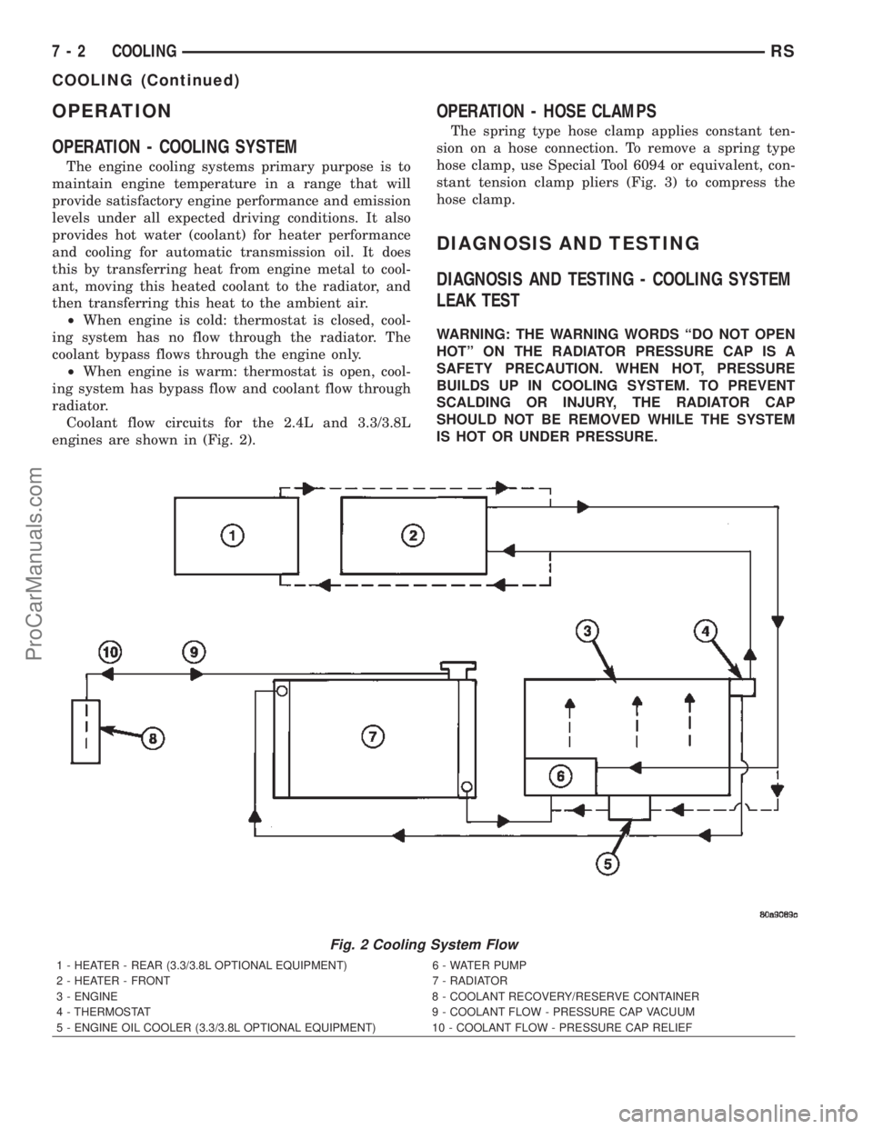
The engine cooling systems primary purpose is to
maintain engine temperature in a range that will
provide satisfactory engine performance and emission
levels under all expected driving conditions. It also
provides hot water (coolant) for heater performance
and cooling for automatic transmission oil. It does
this by transferring heat from engine metal to cool-
ant, moving this heated coolant to the radiator, and
then transferring this heat to the ambient air.
²When engine is cold: thermostat is closed, cool-
ing system has no flow through the radiator. The
coolant bypass flows through the engine only.
²When engine is warm: thermostat is open, cool-
ing system has bypass flow and coolant flow through
radiator.
Coolant flow circuits for the 2.4L and 3.3/3.8L
engines are shown in (Fig. 2).
OPERATION - HOSE CLAMPS
The spring type hose clamp applies constant ten-
sion on a hose connection. To remove a spring type
hose clamp, use Special Tool 6094 or equivalent, con-
stant tension clamp pliers (Fig. 3) to compress the
hose clamp.
DIAGNOSIS AND TESTING
DIAGNOSIS AND TESTING - COOLING SYSTEM
LEAK TEST
WARNING: THE WARNING WORDS ªDO NOT OPEN
HOTº ON THE RADIATOR PRESSURE CAP IS A
SAFETY PRECAUTION. WHEN HOT, PRESSURE
BUILDS UP IN COOLING SYSTEM. TO PREVENT
SCALDING OR INJURY, THE RADIATOR CAP
SHOULD NOT BE REMOVED WHILE THE SYSTEM
IS HOT OR UNDER PRESSURE.
Fig. 2 Cooling System Flow
1 - HEATER - REAR (3.3/3.8L OPTIONAL EQUIPMENT) 6 - WATER PUMP
2 - HEATER - FRONT 7 - RADIATOR
3 - ENGINE 8 - COOLANT RECOVERY/RESERVE CONTAINER
4 - THERMOSTAT 9 - COOLANT FLOW - PRESSURE CAP VACUUM
5 - ENGINE OIL COOLER (3.3/3.8L OPTIONAL EQUIPMENT) 10 - COOLANT FLOW - PRESSURE CAP RELIEF
7 - 2 COOLINGRS
COOLING (Continued)
ProCarManuals.com
Page 252 of 2399
With engine not running, remove radiator pressure
cap and wipe the radiator filler neck sealing seat
clean. The radiator should be full.
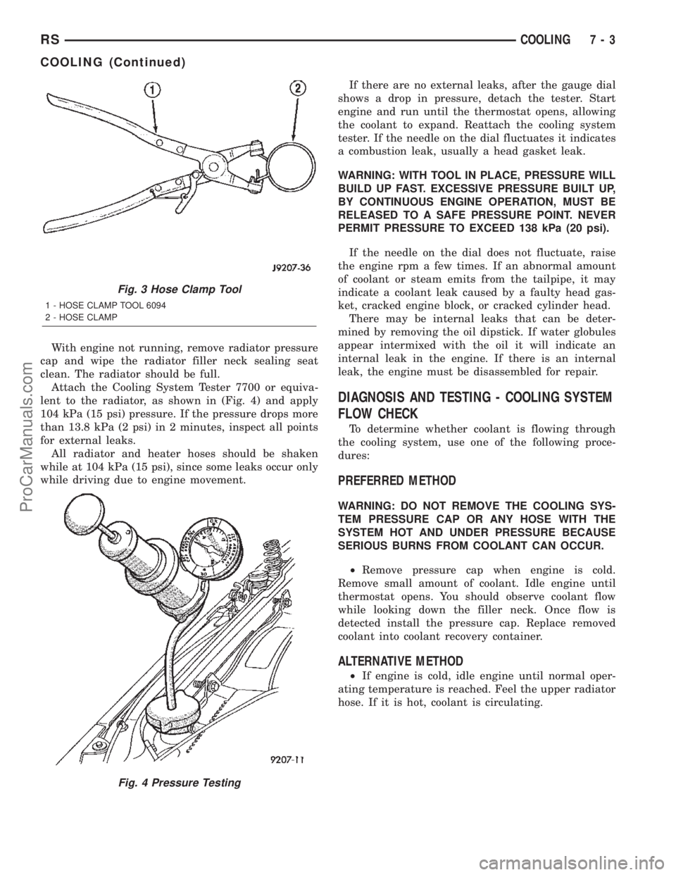
Attach the Cooling System Tester 7700 or equiva-
lent to the radiator, as shown in (Fig. 4) and apply
104 kPa (15 psi) pressure. If the pressure drops more
than 13.8 kPa (2 psi) in 2 minutes, inspect all points
for external leaks.
All radiator and heater hoses should be shaken
while at 104 kPa (15 psi), since some leaks occur only
while driving due to engine movement.If there are no external leaks, after the gauge dial
shows a drop in pressure, detach the tester. Start
engine and run until the thermostat opens, allowing
the coolant to expand. Reattach the cooling system
tester. If the needle on the dial fluctuates it indicates
a combustion leak, usually a head gasket leak.
WARNING: WITH TOOL IN PLACE, PRESSURE WILL
BUILD UP FAST. EXCESSIVE PRESSURE BUILT UP,
BY CONTINUOUS ENGINE OPERATION, MUST BE
RELEASED TO A SAFE PRESSURE POINT. NEVER
PERMIT PRESSURE TO EXCEED 138 kPa (20 psi).
If the needle on the dial does not fluctuate, raise
the engine rpm a few times. If an abnormal amount
of coolant or steam emits from the tailpipe, it may
indicate a coolant leak caused by a faulty head gas-
ket, cracked engine block, or cracked cylinder head.
There may be internal leaks that can be deter-
mined by removing the oil dipstick. If water globules
appear intermixed with the oil it will indicate an
internal leak in the engine. If there is an internal
leak, the engine must be disassembled for repair.
DIAGNOSIS AND TESTING - COOLING SYSTEM
FLOW CHECK
To determine whether coolant is flowing through
the cooling system, use one of the following proce-
dures:
PREFERRED METHOD
WARNING: DO NOT REMOVE THE COOLING SYS-
TEM PRESSURE CAP OR ANY HOSE WITH THE
SYSTEM HOT AND UNDER PRESSURE BECAUSE
SERIOUS BURNS FROM COOLANT CAN OCCUR.
²Remove pressure cap when engine is cold.
Remove small amount of coolant. Idle engine until
thermostat opens. You should observe coolant flow
while looking down the filler neck. Once flow is
detected install the pressure cap. Replace removed
coolant into coolant recovery container.
ALTERNATIVE METHOD
²If engine is cold, idle engine until normal oper-
ating temperature is reached. Feel the upper radiator
hose. If it is hot, coolant is circulating.
Fig. 3 Hose Clamp Tool
1 - HOSE CLAMP TOOL 6094
2 - HOSE CLAMP
Fig. 4 Pressure Testing
RSCOOLING7-3
COOLING (Continued)
ProCarManuals.com
Page 253 of 2399
DIAGNOSIS AND TESTING - COOLING SYSTEM
AERATION
Low coolant level in a cross flow radiator will
equalize in both tanks with engine off. With engine
at running and at operating temperature, the high
pressure inlet tank runs full and the low pressure
outlet tank drops, resulting in cooling system aera-
tion. Aeration will draw air into the water pump
resulting in the following:
²High reading shown on the temperature gauge.
²Loss of coolant flow through the heater core.
²Corrosion in the cooling system.
²Water pump seal may run dry, increasing the
risk of premature seal failure.
²Combustion gas leaks into the coolant can also
cause the above problems.
DIAGNOSIS AND TESTING - COOLING SYSTEM
DEAERATION
Air can only be removed from the system by gath-
ering under the pressure cap. On the next heat up it
will be pushed past the pressure cap into the coolant
recovery bottle by thermal expansion of the coolant.
It then escapes to the atmosphere in the coolant
recovery bottle and is replaced with coolant on cool
down.
To effectively deaerate the system, multiple ther-
mal cycles of the system may be required.
NOTE: Deaeration does not occur at engine idleÐ
higher engine speeds are required. Normal driving
will deaerate cooling system.
STANDARD PROCEDURE
STANDARD PROCEDURE - COOLING SYSTEM
DRAINING
WARNING: DO NOT REMOVE OR LOOSEN THE
COOLANT PRESSURE CAP, CYLINDER BLOCK
DRAIN PLUGS, OR THE DRAINCOCK WHEN THE
SYSTEM IS HOT AND UNDER PRESSURE
BECAUSE SERIOUS BURNS FROM THE COOLANT
CAN OCCUR.
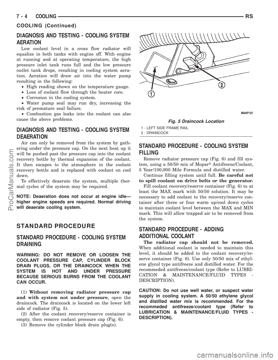
(1)Without removing radiator pressure cap
and with system not under pressure, open the
draincock. The draincock is located on the lower left
side of radiator (Fig. 5).
(2) After the coolant recovery/reserve container is
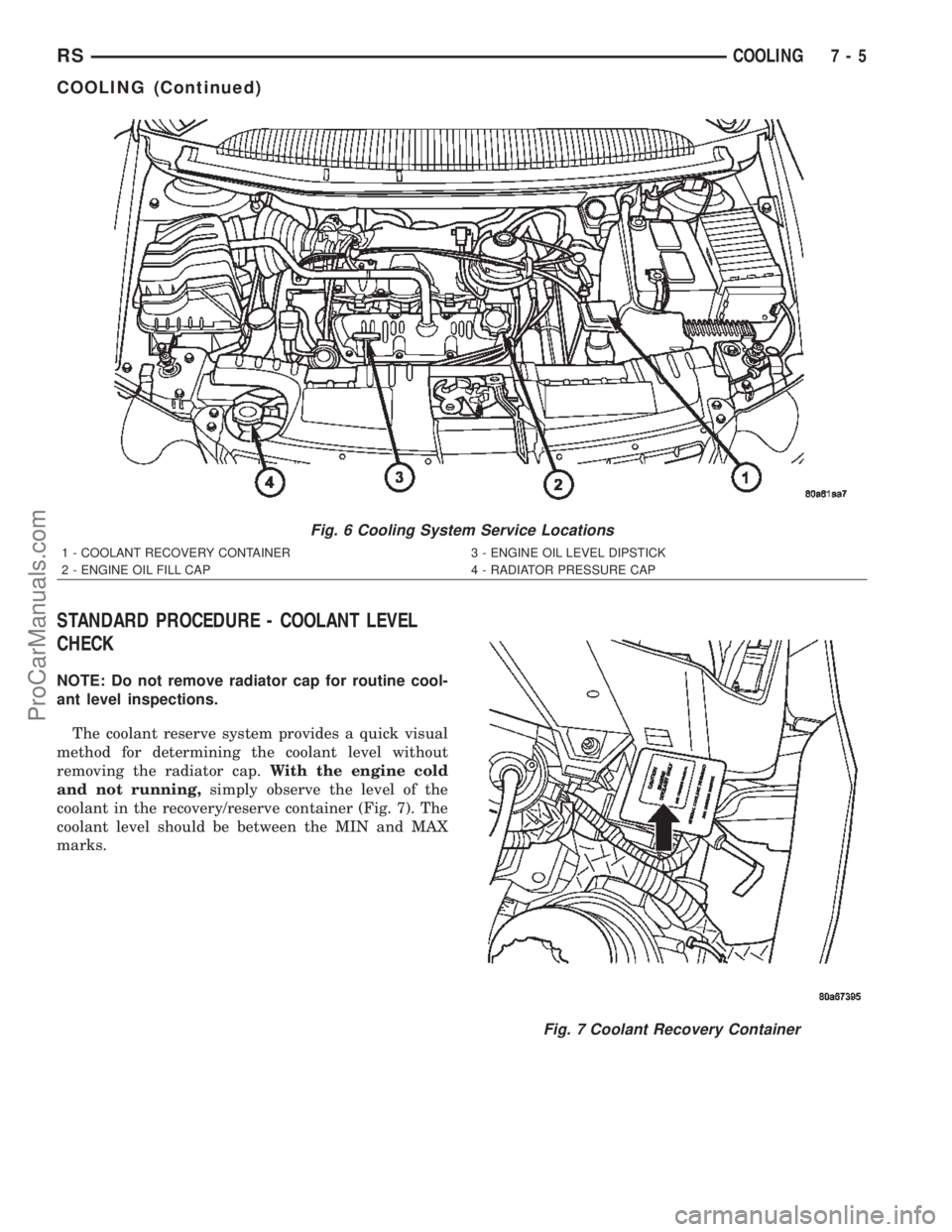
empty, then remove coolant pressure cap (Fig. 6).
(3) Remove the cylinder block drain plug(s).
STANDARD PROCEDURE - COOLING SYSTEM
FILLING
Remove radiator pressure cap (Fig. 6) and fill sys-
tem, using a 50/50 mix of MopartAntifreeze/Coolant,
5 Year/100,000 Mile Formula and distilled water.
Continue filling system until full.Be careful not
to spill coolant on drive belts or the generator.
Fill coolant recovery/reserve container (Fig. 6) to at
least the MAX mark with 50/50 solution. It may be
necessary to add coolant to the recovery/reserve con-
tainer after three or four warm up/cool down cycles
to maintain coolant level between the MAX and MIN
mark. This will allow trapped air to be removed from
the system.
STANDARD PROCEDURE - ADDING
ADDITIONAL COOLANT
The radiator cap should not be removed.
When additional coolant is needed to maintain this
level, it should be added to the coolant recovery/re-
serve container (Fig. 6). Use only 50/50 mix of ethyl-
ene glycol type antifreeze and distilled water. For the
recommeded antifreeze/coolant type (Refer to LUBRI-
CATION & MAINTENANCE/FLUID TYPES -
DESCRIPTION).
CAUTION: Do not use well water, or suspect water
supply in cooling system. A 50/50 ethylene glycol
and distilled water mix is recommended. For the
recommeded antifreeze/coolant type (Refer to
LUBRICATION & MAINTENANCE/FLUID TYPES -
DESCRIPTION).
Fig. 5 Draincock Location
1 - LEFT SIDE FRAME RAIL
2 - DRAINCOCK
7 - 4 COOLINGRS
COOLING (Continued)
ProCarManuals.com
Page 254 of 2399
STANDARD PROCEDURE - COOLANT LEVEL
CHECK
NOTE: Do not remove radiator cap for routine cool-
ant level inspections.
The coolant reserve system provides a quick visual
method for determining the coolant level without
removing the radiator cap.With the engine cold
and not running,simply observe the level of the
coolant in the recovery/reserve container (Fig. 7). The
coolant level should be between the MIN and MAX
marks.
Fig. 6 Cooling System Service Locations
1 - COOLANT RECOVERY CONTAINER 3 - ENGINE OIL LEVEL DIPSTICK
2 - ENGINE OIL FILL CAP 4 - RADIATOR PRESSURE CAP
Fig. 7 Coolant Recovery Container
RSCOOLING7-5
COOLING (Continued)
ProCarManuals.com