2002 DODGE TOWN AND COUNTRY remove seats
[x] Cancel search: remove seatsPage 619 of 2399
(10) Install floor anchor bolt. Tighten seat belt
anchor bolts to 39 N´m (29 ft. lbs.) torque.
(11) Slide floor anchor cover over the anchor bolt.
(12) Install shoulder harness height adjuster knob
by pushing knob on the adjuster.
SEAT BELT FIRST ROW
OUTBOARD - LWB FOUR DOOR
REMOVAL
(1) Remove first and second row seats. Refer to
Owner's manual for proper procedures.
(2) Remove shoulder harness height adjuster knob
by pulling it straight away from adjuster.
(3) Slide floor anchor cover from over the anchor
bolt.
(4) Remove floor anchor bolt.
(5) Remove anchor from floor.
(6) Open clam shell cover from over seat belt turn-
ing loop.
(7) Remove bolt attaching turning loop to shoulder
belt height adjuster.
(8) Remove turning loop from C-pillar.
(9) Remove lower quarter trim panel.
(10) Route seat belt webbing and turning loop
through access hole in lower quarter trim panel.
(11) Remove bolt attaching seat belt retractor to
quarter panel.
(12) Lift retractor upward and disengage arrow
head retainer attaching retractor to quarter panel.
(13) Remove seat belt from vehicle.
INSTALLATION
(1) Position seat belt to vehicle.
(2) Install arrow head retainer to quarter panel
and push downward to seat retainer.
(3) Install bolt attaching seat belt retractor to
quarter panel.
(4) Route seat belt webbing and turning loop
through access hole in lower quarter trim panel.
(5) Install lower quarter trim panel.
(6) Position turning loop to C-pillar.
(7) Install bolt attaching turning loop to shoulder
belt height adjuster.
(8) Close clam shell cover from over seat belt turn-
ing loop.
(9) Position anchor to floor.
(10) Install floor anchor bolt.
(11) Slide floor anchor cover over the anchor bolt.
(12) Install shoulder harness height adjuster knob
by pushing it straight onto adjuster.
(13) Install first and second row seats. Refer to
Owner's manual for proper procedures.NOTE: The tightening specification for all seat belt
anchor bolts is 39 N´m (29 ft. lbs.) torque.
SEAT BELT SECOND RIGHT
ROW OUTBOARD - LWB
REMOVAL
(1) Remove second row seat from vehicle. Refer to
Owner's Manual for proper procedures.
(2) Slide lower anchor cover from over the anchor
shoulder-nut.
(3) Remove lower anchor shoulder-nut (Fig. 5).
(4) Remove lower anchor from wheelhouse.
(5) Fold upper turning loop extension cover down-
ward to gain access to anchor bolt.
(6) Remove bolt attaching turning loop to exten-
sion bracket above quarter glass (Fig. 5).
(7) Remove turning loop from extension bracket.
(8) Remove D-pillar trim panel.
(9) Remove quarter trim bolster.
(10) Route seat belt webbing and turning loop
through access hole in quarter trim.
(11) Remove bolt attaching retractor to inner quar-
ter panel (Fig. 5).
(12) Remove screw attaching retractor to inner
quarter panel.
(13) Remove second row seat belt retractor from
vehicle.
INSTALLATION
(1) Position second row seat belt retractor in vehi-
cle.
(2) Install screw attaching retractor to inner quar-
ter panel.
(3) Install bolt attaching retractor to inner quarter
panel. Tightening specifications for all seat belt bolts
is 39 N´m (29 ft. lbs.) torque.
(4) Route seat belt webbing and turning loop
through access hole in quarter trim.
(5) Install quarter trim bolster.
(6) Install D-pillar trim panel.
(7) Position turning loop to extension bracket.
(8) Install bolt attaching turning loop to extension
bracket above quarter glass. Tightening specifications
for all seat belt bolts is 39 N´m (29 ft. lbs.) torque.
(9) Install upper turning loop extension cover.
(10) Position lower anchor to wheelhouse.
(11) Install lower anchor shoulder-nut. Tightening
shoulder nut to 39 N´m (29 ft. lbs.) torque.
(12) Install lower anchor cover over the anchor
shoulder-nut.
8O - 10 RESTRAINTSRS
SEAT BELT FIRST ROW OUTBOARD - SWB FOUR DOOR (Continued)
ProCarManuals.com
Page 1200 of 2399
tion. The IOD fuse is a 15 ampere blade-type car-
tridge fuse and, when removed, it is stored in a fuse
cavity adjacent to the washer fuse within the IPM.
OPERATION
The term ignition-off draw identifies a normal con-
dition where power is being drained from the battery
with the ignition switch in the Off position. The IOD
fuse feeds the memory and sleep mode functions for
some of the electronic modules in the vehicle as well
as various other accessories that require battery cur-
rent when the ignition switch is in the Off position,
including the clock. The only reason the IOD fuse is
removed is to reduce the normal IOD of the vehicle
electrical system during new vehicle transportation
and pre-delivery storage to reduce battery depletion,
while still allowing vehicle operation so that the
vehicle can be loaded, unloaded and moved as needed
by both vehicle transportation company and dealer
personnel.
The IOD fuse is removed from the IPM fuse cavity
when the vehicle is shipped from the assembly plant.
Dealer personnel must install the IOD fuse when the
vehicle is being prepared for delivery in order to
restore full electrical system operation. Once the
vehicle is prepared for delivery, the IOD function of
this fuse becomes transparent and the fuse that has
been assigned the IOD designation becomes only
another Fused B(+) circuit fuse. The IOD fuse serves
no useful purpose to the dealer technician in the ser-
vice or diagnosis of any vehicle system or condition,
other than the same purpose as that of any other
standard circuit protection device.
The IOD fuse can be used by the vehicle owner as
a convenient means of reducing battery depletion
when a vehicle is to be stored for periods not to
exceed about thirty days. However, it must be
remembered that removing the IOD fuse will not
eliminate IOD, but only reduce this normal condition.
If a vehicle will be stored for more than about thirty
days, the battery negative cable should be discon-
nected to eliminate normal IOD; and, the battery
should be tested and recharged at regular intervals
during the vehicle storage period to prevent the bat-
tery from becoming discharged or damaged. Refer to
Battery Systemfor additional service information.
REMOVAL
(1) Turn the ignition switch to the Off position.
(2) Unlatch and open the cover of the intelligent
power module.
(3) Remove the IOD fuse from fuse location
markedIODof the Integrated Power Module (IPM).
(4) Store the removed IOD fuse by installing it in
the unused fuse storage markedSPAREof the IPM.
(5) Close and latch the IPM.
INSTALLATION
(1) Be certain the ignition switch is in the Off posi-
tion.
(2) Unlatch and open the cover of the Integrated
Power Module (IPM).
(3) Remove the stored 15 amp IOD fuse from fuse
storage markedSPAREof the IPM.
(4) Use a thumb to press the IOD fuse firmly down
into IPM fuse cavity markedIOD.
(5) Close and latch the IPM cover.
POWER OUTLET
DESCRIPTION
Accessory power outlets are standard equipment on
this model. Two power outlets are installed in the
instrument panel center lower bezel, which is located
near the bottom of the instrument panel center stack
area. Two additional power outlets are also incorpo-
rated into the vehicle, one on the left rear C-pillar
trim and the other in the center console, if equipped.
The power outlets bases are secured by a snap fit in
the appropriate bezels. A hinged plug flips closed to
conceal and protect the power outlet base when the
power outlet is not being used.
The power outlet receptacle unit and the power
outlet plugs are each available for service replace-
ment.
OPERATION
The power outlet base or receptacle shell is con-
nected to ground, and an insulated contact in the
bottom of the shell is connected to battery current.
The power outlet on the instrument panel marked
with a battery receives battery voltage from a fuse in
the Integrated Power Module (IPM) at all times. The
other power outlet on the instrument panel marked
with a key receives battery voltage only when the
key is in the on position.
The power outlet located in the center console
receives battery voltage all the time when positioned
between thefront seatsand key-on voltage when
positioned between therear seats. The power outlet
located on the C-pillar receives battery voltage only
when the key is in the on position.
DIAGNOSIS AND TESTING
DIAGNOSIS & TESTING - POWER OUTLET
For complete circuit diagrams, refer toCigar
Lighter/Power Outletin Wiring Diagrams.
RS8W-97 POWER DISTRIBUTION SYSTEM8W-97-5
IOD FUSE (Continued)
ProCarManuals.com
Page 1225 of 2399
AIR CLEANER ELEMENT
REMOVAL
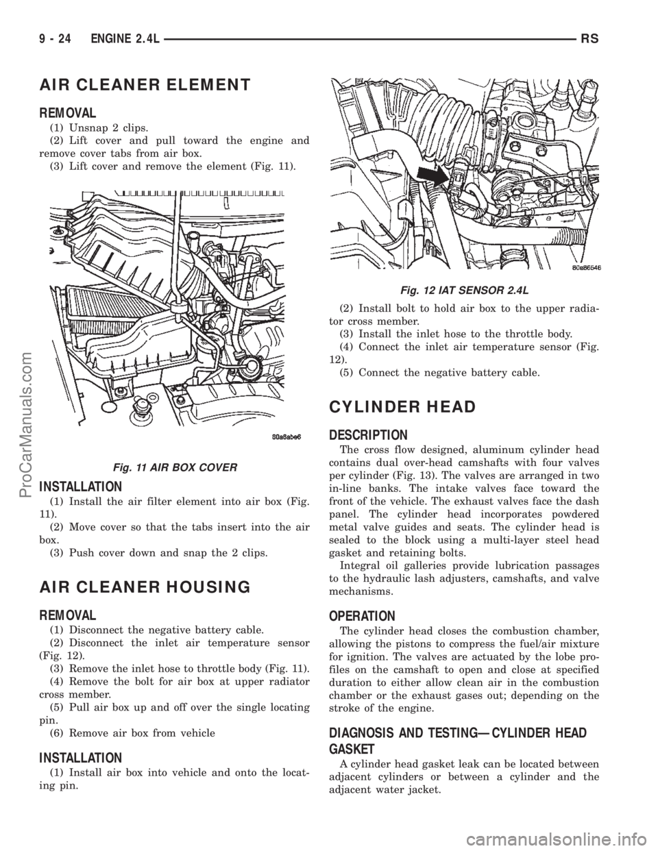
(1) Unsnap 2 clips.
(2) Lift cover and pull toward the engine and
remove cover tabs from air box.
(3) Lift cover and remove the element (Fig. 11).
INSTALLATION
(1) Install the air filter element into air box (Fig.
11).
(2) Move cover so that the tabs insert into the air
box.
(3) Push cover down and snap the 2 clips.
AIR CLEANER HOUSING
REMOVAL
(1) Disconnect the negative battery cable.
(2) Disconnect the inlet air temperature sensor
(Fig. 12).
(3) Remove the inlet hose to throttle body (Fig. 11).
(4) Remove the bolt for air box at upper radiator
cross member.
(5) Pull air box up and off over the single locating
pin.
(6) Remove air box from vehicle
INSTALLATION
(1) Install air box into vehicle and onto the locat-
ing pin.(2) Install bolt to hold air box to the upper radia-
tor cross member.
(3) Install the inlet hose to the throttle body.
(4) Connect the inlet air temperature sensor (Fig.
12).
(5) Connect the negative battery cable.
CYLINDER HEAD
DESCRIPTION
The cross flow designed, aluminum cylinder head
contains dual over-head camshafts with four valves
per cylinder (Fig. 13). The valves are arranged in two
in-line banks. The intake valves face toward the
front of the vehicle. The exhaust valves face the dash
panel. The cylinder head incorporates powdered
metal valve guides and seats. The cylinder head is
sealed to the block using a multi-layer steel head
gasket and retaining bolts.
Integral oil galleries provide lubrication passages
to the hydraulic lash adjusters, camshafts, and valve
mechanisms.
OPERATION
The cylinder head closes the combustion chamber,
allowing the pistons to compress the fuel/air mixture
for ignition. The valves are actuated by the lobe pro-
files on the camshaft to open and close at specified
duration to either allow clean air in the combustion
chamber or the exhaust gases out; depending on the
stroke of the engine.
DIAGNOSIS AND TESTINGÐCYLINDER HEAD
GASKET
A cylinder head gasket leak can be located between
adjacent cylinders or between a cylinder and the
adjacent water jacket.
Fig. 11 AIR BOX COVER
Fig. 12 IAT SENSOR 2.4L
9 - 24 ENGINE 2.4LRS
ProCarManuals.com
Page 1233 of 2399
INTAKE/EXHAUST VALVES &
SEATS
DESCRIPTION
The valves are made of heat resistant steel. They
have chrome plated stems to prevent scuffing. Viton
rubber valve stem seals are integral with the spring
seats. The valves have three-bead lock keepers to
retain springs and to promote valve rotation.
CLEANING
(1) Clean all valves thoroughly and discard
burned, warped and cracked valves.
VALVE SPRINGS & SEALS
REMOVAL
REMOVAL - CYLINDER HEAD ON
(1) Remove cylinder head cover (Refer to 9 -
ENGINE/CYLINDER HEAD/CYLINDER HEAD
COVER(S) - REMOVAL).
(2) Remove camshafts (Refer to 9 - ENGINE/CYL-
INDER HEAD/CAMSHAFT(S) - REMOVAL).
(3) Rotate crankshaft until piston is at TDC on
compression.
(4) With air hose attached to adapter tool installed
in spark plug hole, apply 90-120 psi air pressure.
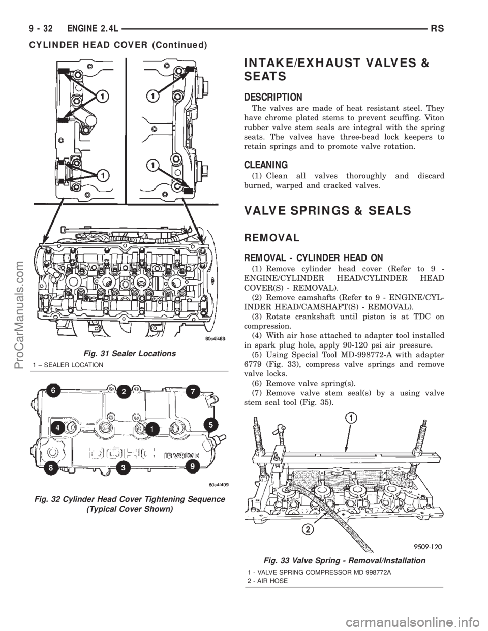
(5) Using Special Tool MD-998772-A with adapter
6779 (Fig. 33), compress valve springs and remove
valve locks.
(6) Remove valve spring(s).
(7) Remove valve stem seal(s) by a using valve
stem seal tool (Fig. 35).
Fig. 31 Sealer Locations
1 ± SEALER LOCATION
Fig. 32 Cylinder Head Cover Tightening Sequence
(Typical Cover Shown)
Fig. 33 Valve Spring - Removal/Installation
1 - VALVE SPRING COMPRESSOR MD 998772A
2 - AIR HOSE
9 - 32 ENGINE 2.4LRS
CYLINDER HEAD COVER (Continued)
ProCarManuals.com
Page 1301 of 2399
INSTALLATION
(1) Install air box into vehicle and onto the locat-
ing pin.
(2) Install bolt to hold air box to the upper radia-
tor cross member.
(3) Install the inlet hose to the throttle body.
(4) Connect the inlet air temperature sensor (Fig.
16).
(5) Connect the negative battery cable.
CYLINDER HEAD
DESCRIPTION
The aluminum cylinder heads (Fig. 17) are
designed to create high flow combustion chambers to
improve performance, while minimizing the change
to the burn rate in the chamber. The cylinder head
incorporates the combustion chamber. Two valves
per-cylinder are used with inserted valve seats and
guides. A multi-layer steel (MLS) type gasket is used
between the cylinder head and engine block.
OPERATION
The cylinder head closes the combustion chamber,
allowing the pistons to compress the fuel/air mixture
for ignition. The valves are actuated by the lobe pro-
files on the camshaft to open and close at specified
duration to either allow clean air in the combustion
chamber or the exhaust gases out; depending on the
stroke of the engine.
DIAGNOSIS AND TESTINGÐCYLINDER HEAD
GASKET
A cylinder head gasket leak can be located between
adjacent cylinders or between a cylinder and the
adjacent water jacket.
Possible indications of the cylinder head gasket
leaking between adjacent cylinders are:
²Loss of engine power
²Engine misfiring
²Poor fuel economy
Possible indications of the cylinder head gasket
leaking between a cylinder and an adjacent water
jacket are:
²Engine overheating
²Loss of coolant
²Excessive steam (white smoke) emitting from
exhaust
²Coolant foaming
CYLINDER-TO-CYLINDER LEAKAGE TEST
To determine if an engine cylinder head gasket is
leaking between adjacent cylinders, follow the proce-
dures in Cylinder Compression Pressure Test (Refer
to 9 - ENGINE - DIAGNOSIS AND TESTING). An
engine cylinder head gasket leaking between adja-
cent cylinders will result in approximately a 50±70%
reduction in compression pressure.
CYLINDER-TO-WATER JACKET LEAKAGE TEST
WARNING: USE EXTREME CAUTION WHEN THE
ENGINE IS OPERATING WITH COOLANT PRES-
SURE CAP REMOVED.
VISUAL TEST METHOD
With the engine cool, remove the coolant pressure
cap. Start the engine and allow it to warm up until
thermostat opens.
If a large combustion/compression pressure leak
exists, bubbles will be visible in the coolant.
COOLING SYSTEM TESTER METHOD
WARNING: WITH COOLING SYSTEM TESTER IN
PLACE, PRESSURE WILL BUILD UP FAST. EXCES-
SIVE PRESSURE BUILT UP, BY CONTINUOUS
ENGINE OPERATION, MUST BE RELEASED TO A
SAFE PRESSURE POINT. NEVER PERMIT PRES-
SURE TO EXCEED 138 kPa (20 psi).
Install Cooling System Tester 7700 or equivalent to
pressure cap neck. Start the engine and observe the
tester's pressure gauge. If gauge pulsates with every
power stroke of a cylinder a combustion pressure
leak is evident.
CHEMICAL TEST METHOD
Combustion leaks into the cooling system can also
be checked by using Bloc-Chek Kit C-3685-A or
equivalent. Perform test following the procedures
supplied with the tool kit.
REMOVAL - CYLINDER HEAD
(1) Drain the cooling system. (Refer to 7 - COOL-
ING - STANDARD PROCEDURE)
(2) Disconnect negative cable from battery.
(3) Remove upper and lower intake manifolds.
(Refer to 9 - ENGINE/MANIFOLDS/INTAKE MANI-
FOLD - REMOVAL)
WARNING: INTAKE MANIFOLD GASKET IS MADE
OF VERY THIN METAL AND MAY CAUSE PER-
SONAL INJURY, HANDLE WITH CARE.
9 - 100 ENGINE 3.3/3.8LRS
AIR CLEANER HOUSING (Continued)
ProCarManuals.com
Page 1302 of 2399
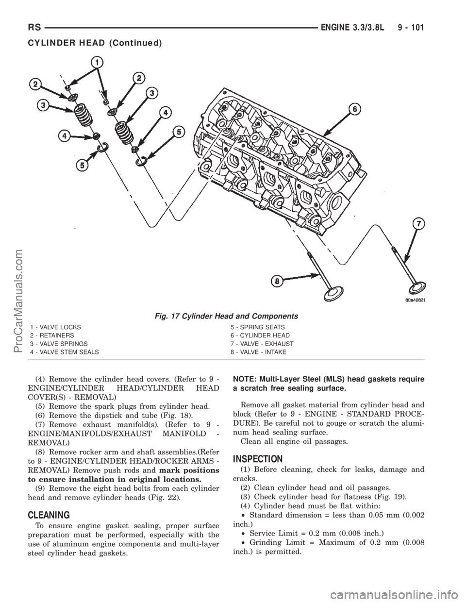
(4) Remove the cylinder head covers. (Refer to 9 -
ENGINE/CYLINDER HEAD/CYLINDER HEAD
COVER(S) - REMOVAL)
(5) Remove the spark plugs from cylinder head.
(6) Remove the dipstick and tube (Fig. 18).
(7) Remove exhaust manifold(s). (Refer to 9 -
ENGINE/MANIFOLDS/EXHAUST MANIFOLD -
REMOVAL)
(8) Remove rocker arm and shaft assemblies.(Refer
to 9 - ENGINE/CYLINDER HEAD/ROCKER ARMS -
REMOVAL) Remove push rods andmark positions
to ensure installation in original locations.
(9) Remove the eight head bolts from each cylinder
head and remove cylinder heads (Fig. 22).
CLEANING
To ensure engine gasket sealing, proper surface
preparation must be performed, especially with the
use of aluminum engine components and multi-layer
steel cylinder head gaskets.NOTE: Multi-Layer Steel (MLS) head gaskets require
a scratch free sealing surface.
Remove all gasket material from cylinder head and
block (Refer to 9 - ENGINE - STANDARD PROCE-
DURE). Be careful not to gouge or scratch the alumi-
num head sealing surface.
Clean all engine oil passages.
INSPECTION
(1) Before cleaning, check for leaks, damage and
cracks.
(2) Clean cylinder head and oil passages.
(3) Check cylinder head for flatness (Fig. 19).
(4) Cylinder head must be flat within:
²Standard dimension = less than 0.05 mm (0.002
inch.)
²Service Limit = 0.2 mm (0.008 inch.)
²Grinding Limit = Maximum of 0.2 mm (0.008
inch.) is permitted.
Fig. 17 Cylinder Head and Components
1 - VALVE LOCKS 5 - SPRING SEATS
2 - RETAINERS 6 - CYLINDER HEAD
3 - VALVE SPRINGS 7 - VALVE - EXHAUST
4 - VALVE STEM SEALS 8 - VALVE - INTAKE
RSENGINE 3.3/3.8L9 - 101
CYLINDER HEAD (Continued)
ProCarManuals.com
Page 1306 of 2399
CYLINDER HEAD COVER -
LEFT
REMOVAL
(1) Disconnect spark plug wires from spark plugs.
(2) Disconnect crankcase vent hose from cylinder
head cover.
(3) Remove cylinder head cover bolts.
(4) Remove cylinder head cover and gasket.
INSTALLATION
(1) Clean cylinder head and cover mating surfaces.
Inspect cylinder head cover surface for flatness.
Replace gasket as necessary.
(2) Assemble gasket to cylinder cover by inserting
the fasteners through each bolt hole on cover and
gasket (Fig. 26).
(3) Install the cylinder head cover and bolts (Fig.
27).
(4) Tighten cylinder head cover bolts to 12 N´m
(105 in. lbs.) (Fig. 27).
(5) Connect crankcase vent hose.
(6) Connect spark plug wires to spark plugs.
INTAKE/EXHAUST VALVES &
SEATS
DESCRIPTION
The valves have chrome plated valve stems with
four-bead lock grooves. The valve stem seals are
made of Viton rubber.
OPERATION
The two valves per cylinder are opened using
hydraulic lifters, push rods, and rocker arms.
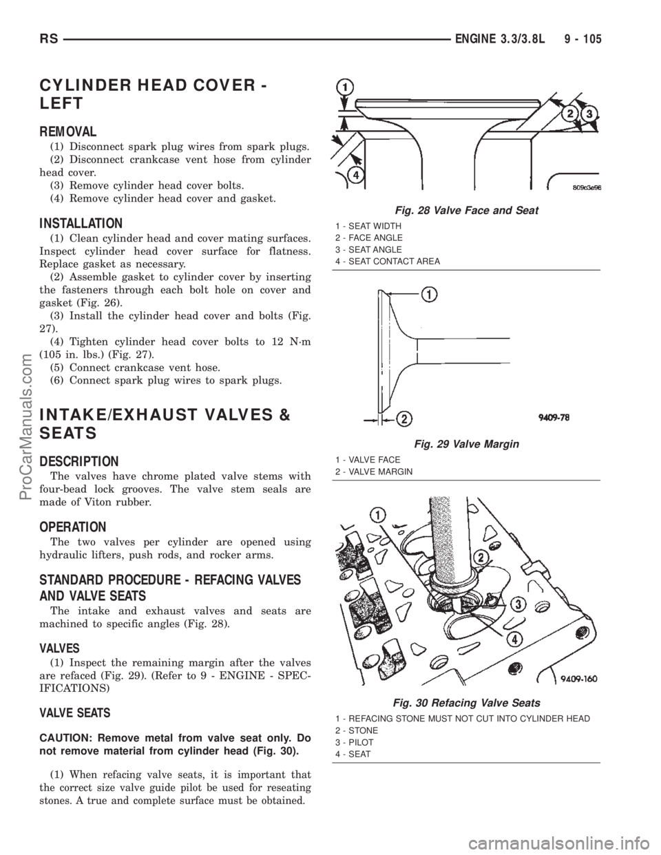
STANDARD PROCEDURE - REFACING VALVES
AND VALVE SEATS
The intake and exhaust valves and seats are
machined to specific angles (Fig. 28).
VALVES
(1) Inspect the remaining margin after the valves
are refaced (Fig. 29). (Refer to 9 - ENGINE - SPEC-
IFICATIONS)
VALVE SEATS
CAUTION: Remove metal from valve seat only. Do
not remove material from cylinder head (Fig. 30).
(1)
When refacing valve seats, it is important that
the correct size valve guide pilot be used for reseating
stones. A true and complete surface must be obtained.
Fig. 28 Valve Face and Seat
1 - SEAT WIDTH
2 - FACE ANGLE
3 - SEAT ANGLE
4 - SEAT CONTACT AREA
Fig. 29 Valve Margin
1 - VALVE FACE
2 - VALVE MARGIN
Fig. 30 Refacing Valve Seats
1 - REFACING STONE MUST NOT CUT INTO CYLINDER HEAD
2-STONE
3 - PILOT
4 - SEAT
RSENGINE 3.3/3.8L9 - 105
ProCarManuals.com
Page 1307 of 2399
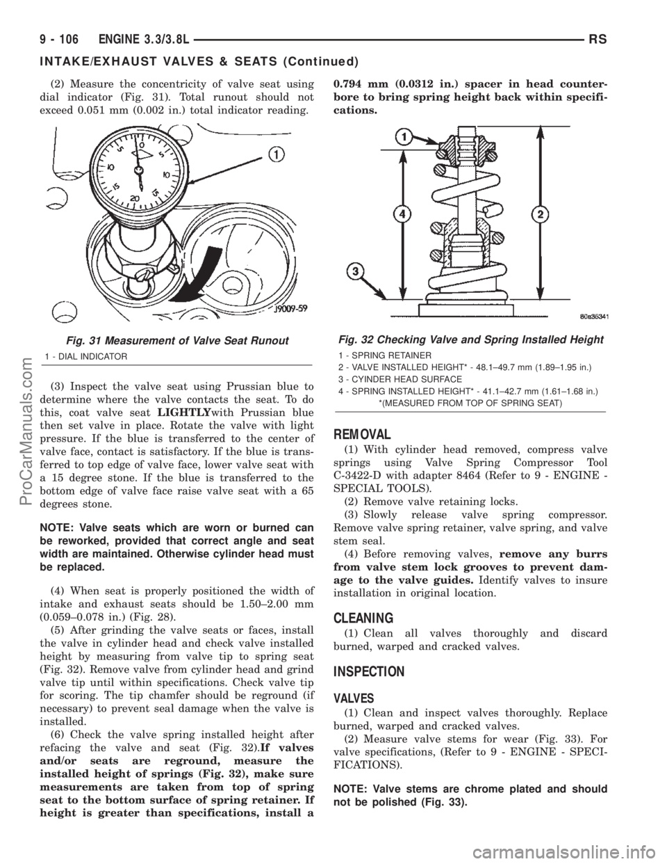
(2) Measure the concentricity of valve seat using
dial indicator (Fig. 31). Total runout should not
exceed 0.051 mm (0.002 in.) total indicator reading.
(3) Inspect the valve seat using Prussian blue to
determine where the valve contacts the seat. To do
this, coat valve seatLIGHTLYwith Prussian blue
then set valve in place. Rotate the valve with light
pressure. If the blue is transferred to the center of
valve face, contact is satisfactory. If the blue is trans-
ferred to top edge of valve face, lower valve seat with
a 15 degree stone. If the blue is transferred to the
bottom edge of valve face raise valve seat with a 65
degrees stone.
NOTE: Valve seats which are worn or burned can
be reworked, provided that correct angle and seat
width are maintained. Otherwise cylinder head must
be replaced.
(4) When seat is properly positioned the width of
intake and exhaust seats should be 1.50±2.00 mm
(0.059±0.078 in.) (Fig. 28).
(5) After grinding the valve seats or faces, install
the valve in cylinder head and check valve installed
height by measuring from valve tip to spring seat
(Fig. 32). Remove valve from cylinder head and grind
valve tip until within specifications. Check valve tip
for scoring. The tip chamfer should be reground (if
necessary) to prevent seal damage when the valve is
installed.
(6) Check the valve spring installed height after
refacing the valve and seat (Fig. 32).If valves
and/or seats are reground, measure the
installed height of springs (Fig. 32), make sure
measurements are taken from top of spring
seat to the bottom surface of spring retainer. If
height is greater than specifications, install a0.794 mm (0.0312 in.) spacer in head counter-
bore to bring spring height back within specifi-
cations.
REMOVAL
(1) With cylinder head removed, compress valve
springs using Valve Spring Compressor Tool
C-3422-D with adapter 8464 (Refer to 9 - ENGINE -
SPECIAL TOOLS).
(2) Remove valve retaining locks.
(3) Slowly release valve spring compressor.
Remove valve spring retainer, valve spring, and valve
stem seal.
(4) Before removing valves,remove any burrs
from valve stem lock grooves to prevent dam-
age to the valve guides.Identify valves to insure
installation in original location.
CLEANING
(1) Clean all valves thoroughly and discard
burned, warped and cracked valves.
INSPECTION
VALVES
(1) Clean and inspect valves thoroughly. Replace
burned, warped and cracked valves.
(2) Measure valve stems for wear (Fig. 33). For
valve specifications, (Refer to 9 - ENGINE - SPECI-
FICATIONS).
NOTE: Valve stems are chrome plated and should
not be polished (Fig. 33).
Fig. 31 Measurement of Valve Seat Runout
1 - DIAL INDICATOR
Fig. 32 Checking Valve and Spring Installed Height
1 - SPRING RETAINER
2 - VALVE INSTALLED HEIGHT* - 48.1±49.7 mm (1.89±1.95 in.)
3 - CYINDER HEAD SURFACE
4 - SPRING INSTALLED HEIGHT* - 41.1±42.7 mm (1.61±1.68 in.)
*(MEASURED FROM TOP OF SPRING SEAT)
9 - 106 ENGINE 3.3/3.8LRS
INTAKE/EXHAUST VALVES & SEATS (Continued)
ProCarManuals.com