2002 DODGE TOWN AND COUNTRY evaporator
[x] Cancel search: evaporatorPage 1090 of 2399
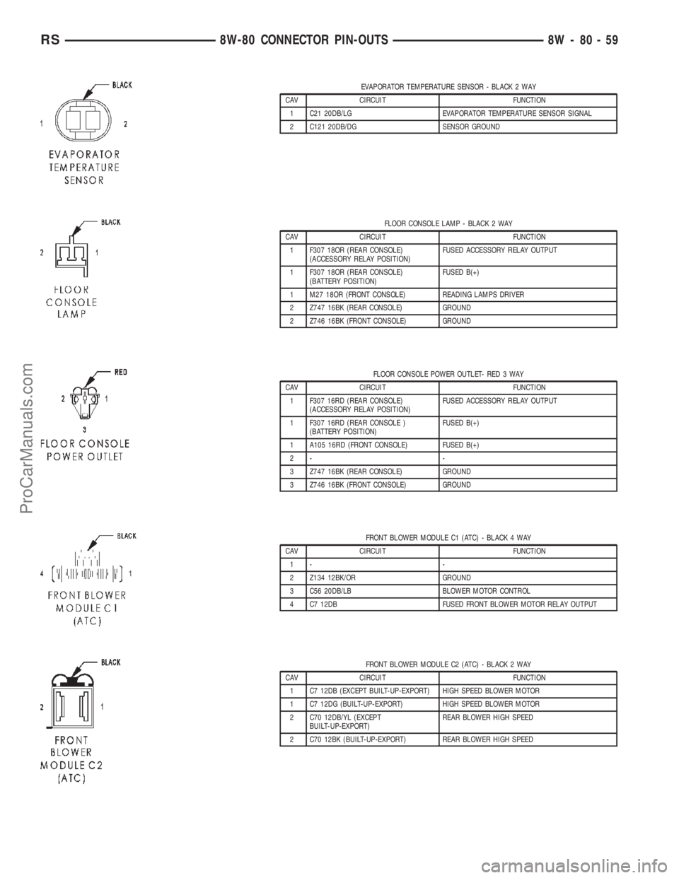
EVAPORATOR TEMPERATURE SENSOR - BLACK 2 WAY
CAV CIRCUIT FUNCTION
1 C21 20DB/LG EVAPORATOR TEMPERATURE SENSOR SIGNAL
2 C121 20DB/DG SENSOR GROUND
FLOOR CONSOLE LAMP - BLACK 2 WAY
CAV CIRCUIT FUNCTION
1 F307 18OR (REAR CONSOLE)
(ACCESSORY RELAY POSITION)FUSED ACCESSORY RELAY OUTPUT
1 F307 18OR (REAR CONSOLE)
(BATTERY POSITION)FUSED B(+)
1 M27 18OR (FRONT CONSOLE) READING LAMPS DRIVER
2 Z747 16BK (REAR CONSOLE) GROUND
2 Z746 16BK (FRONT CONSOLE) GROUND
FLOOR CONSOLE POWER OUTLET- RED 3 WAY
CAV CIRCUIT FUNCTION
1 F307 16RD (REAR CONSOLE)
(ACCESSORY RELAY POSITION)FUSED ACCESSORY RELAY OUTPUT
1 F307 16RD (REAR CONSOLE )
(BATTERY POSITION)FUSED B(+)
1 A105 16RD (FRONT CONSOLE) FUSED B(+)
2- -
3 Z747 16BK (REAR CONSOLE) GROUND
3 Z746 16BK (FRONT CONSOLE) GROUND
FRONT BLOWER MODULE C1 (ATC) - BLACK 4 WAY
CAV CIRCUIT FUNCTION
1- -
2 Z134 12BK/OR GROUND
3 C56 20DB/LB BLOWER MOTOR CONTROL
4 C7 12DB FUSED FRONT BLOWER MOTOR RELAY OUTPUT
FRONT BLOWER MODULE C2 (ATC) - BLACK 2 WAY
CAV CIRCUIT FUNCTION
1 C7 12DB (EXCEPT BUILT-UP-EXPORT) HIGH SPEED BLOWER MOTOR
1 C7 12DG (BUILT-UP-EXPORT) HIGH SPEED BLOWER MOTOR
2 C70 12DB/YL (EXCEPT
BUILT-UP-EXPORT)REAR BLOWER HIGH SPEED
2 C70 12BK (BUILT-UP-EXPORT) REAR BLOWER HIGH SPEED
RS8W-80 CONNECTOR PIN-OUTS8W-80-59
ProCarManuals.com
Page 1151 of 2399

CONNECTOR NAME/NUMBER COLOR LOCATION FIG.
Driver Power Seat Front Riser
MotorRD At Seat N/S
Driver Power Seat Horizontal Motor BK At Seat N/S
Driver Power Seat Rear Riser
MotorRD At Seat N/S
Driver Power Seat Recliner Motor GN At Seat N/S
Driver Power Seat Switch GN At Switch N/S
Driver Power Window Motor RD At Motor N/S
Driver Power Window Switch GN At Switch N/S
Driver Power Window Switch
(RHD)NAT At Switch N/S
Driver Seatbelt Switch WT At Switch on Seat Harness N/S
Driver Seatbelt Tensioner On Seat Harness N/S
EGR Solenoid (Diesel) BK Above Transmission
Right Side of EngineN/S
EGR Solenoid GY Above Transmission
Right Side of Engine9, 10, 11, 13
Electric Wiper De-Icer-C1 WT Right Side Instrument Panel 15, 1923
Electric Wiper De-Icer-C2 WT Left Side Instrument Panel 15, 16, 22
Engine Control Module C1 (Diesel) BK Right Side of Engine 11
Engine Control Module C2 (Diesel) BK Right Side of Engine 11
Engine Coolant Temperature
Sensor (Gas)BK On Cylinder Block N/S
Engine Coolant Temperature
Sensor (Diesel)BL On Cylinder Block 11
Engine Oil Pressure Sensor
(Diesel)BK Rear of Engine 12
Engine Oil Pressure Switch (Gas) LTGN On Cylinder Block 9
Engine Oil Temperature Sensor
(Diesel)BK Rear of Engine 12
EVAP/Purge Solenoid BK Right Motor Mount 9, 13
Evaporator Temperature Sensor BK Right Side of HVAC N/S
Floor Console Lamp BK At Lamp N/S
Floor Console Power Outlet RD At Front Console N/S
Front Blower Module C1 (ATC) BK On HVAC N/S
Front Blower Module C2 (ATC) BK On HVAC N/S
Front Cigar Lighter RD/NAT Rear of Lighter 15, 18, 20
Front Reading Lamps/Switch BK At Switch N/S
Front Washer Pump Motor BK Right Fender Well 3
Fuel Heater (Diesel) BK Left Rear Engine Compartment N/S
Fuel Injector No.1 BK At Fuel Injector N/S
Fuel Injector No.1 (Diesel) BK At Fuel Injector 11
Fuel Injector No.2 BK At Fuel Injector N/S
Fuel Injector No.2 (Diesel) BK At Fuel Injector 11
8W - 91 - 4 8W-91 CONNECTOR/GROUND/SPLICE LOCATIONRS
CONNECTOR/GROUND/SPLICE LOCATION (Continued)
ProCarManuals.com
Page 1471 of 2399
Long Term
The second fuel correction program is the long
term adaptive memory. In order to maintain correct
emission throughout all operating ranges of the
engine, a cell structure based on engine rpm and load
(MAP) is used.
Ther number of cells varies upon the driving con-
ditions. Two cells are used only during idle, based
upon TPS and Park/Neutral switch inputs. There
may be two other cells used for deceleration, based
on TPS, engine rpm, and vehicle speed. The other
twelve cells represent a manifold pressure and an
rpm range. Six of the cells are high rpm and the
other six are low rpm. Each of these cells is a specific
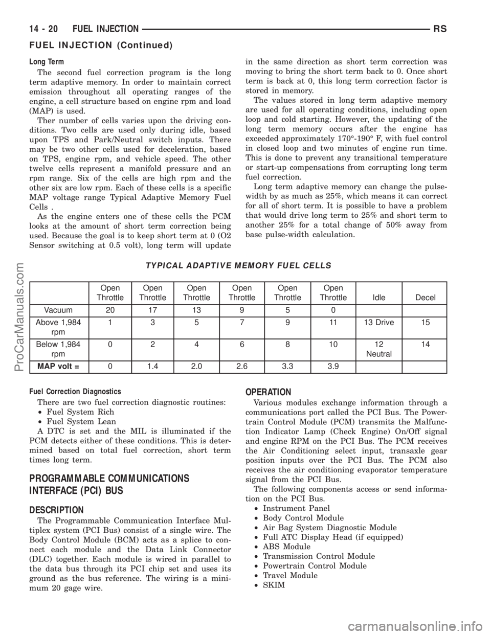
MAP voltage range Typical Adaptive Memory Fuel
Cells .
As the engine enters one of these cells the PCM
looks at the amount of short term correction being
used. Because the goal is to keep short term at 0 (O2
Sensor switching at 0.5 volt), long term will updatein the same direction as short term correction was
moving to bring the short term back to 0. Once short
term is back at 0, this long term correction factor is
stored in memory.
The values stored in long term adaptive memory
are used for all operating conditions, including open
loop and cold starting. However, the updating of the
long term memory occurs after the engine has
exceeded approximately 170É-190É F, with fuel control
in closed loop and two minutes of engine run time.
This is done to prevent any transitional temperature
or start-up compensations from corrupting long term
fuel correction.
Long term adaptive memory can change the pulse-
width by as much as 25%, which means it can correct
for all of short term. It is possible to have a problem
that would drive long term to 25% and short term to
another 25% for a total change of 50% away from
base pulse-width calculation.
TYPICAL ADAPTIVE MEMORY FUEL CELLS
Open
ThrottleOpen
ThrottleOpen
ThrottleOpen
ThrottleOpen
ThrottleOpen
Throttle Idle Decel
Vacuum 20 17 13 9 5 0
Above 1,984
rpm1 3 5 7 9 11 13 Drive 15
Below 1,984
rpm02 4 6 8 1012
Neutral14
MAP volt =0 1.4 2.0 2.6 3.3 3.9
Fuel Correction Diagnostics
There are two fuel correction diagnostic routines:
²Fuel System Rich
²Fuel System Lean
A DTC is set and the MIL is illuminated if the
PCM detects either of these conditions. This is deter-
mined based on total fuel correction, short term
times long term.
PROGRAMMABLE COMMUNICATIONS
INTERFACE (PCI) BUS
DESCRIPTION
The Programmable Communication Interface Mul-
tiplex system (PCI Bus) consist of a single wire. The
Body Control Module (BCM) acts as a splice to con-
nect each module and the Data Link Connector
(DLC) together. Each module is wired in parallel to
the data bus through its PCI chip set and uses its
ground as the bus reference. The wiring is a mini-
mum 20 gage wire.
OPERATION
Various modules exchange information through a
communications port called the PCI Bus. The Power-
train Control Module (PCM) transmits the Malfunc-
tion Indicator Lamp (Check Engine) On/Off signal
and engine RPM on the PCI Bus. The PCM receives
the Air Conditioning select input, transaxle gear
position inputs over the PCI Bus. The PCM also
receives the air conditioning evaporator temperature
signal from the PCI Bus.
The following components access or send informa-
tion on the PCI Bus.
²Instrument Panel
²Body Control Module
²Air Bag System Diagnostic Module
²Full ATC Display Head (if equipped)
²ABS Module
²Transmission Control Module
²Powertrain Control Module
²Travel Module
²SKIM
14 - 20 FUEL INJECTIONRS
FUEL INJECTION (Continued)
ProCarManuals.com
Page 2244 of 2399
HEATING & AIR CONDITIONING
TABLE OF CONTENTS
page page
HEATING & AIR CONDITIONING
DESCRIPTION
DESCRIPTION - SINGLE ZONE...........1
DESCRIPTION - DUAL ZONE.............1
DESCRIPTION - MANUAL THREE ZONE.....1
DESCRIPTION - THREE ZONE AUTOMATIC
TEMPERATURE CONTROL...............2
OPERATION
OPERATION - DUAL ZONE...............3
OPERATION - MANUAL THREE ZONE......3
OPERATION - THREE ZONE ATC..........4
DIAGNOSIS AND TESTING
DIAGNOSIS AND TESTING - A/C COOL
DOWN TEST..........................5DIAGNOSIS AND TESTING - A/C
PERFORMANCE TEST..................5
DIAGNOSIS AND TESTING - HEATER
PERFORMANCE TEST..................6
SPECIFICATIONS - HEATER-A/C SYSTEM.....7
CONTROLS - FRONT......................8
CONTROLS - REAR......................29
DISTRIBUTION - FRONT...................39
DISTRIBUTION - REAR....................51
PLUMBING - FRONT.....................59
PLUMBING - REAR......................97
DIESEL SUPPLEMENTAL HEATER - DCHA -
BUX.................................109
HEATING & AIR
CONDITIONING
DESCRIPTION
DESCRIPTION - SINGLE ZONE
A single zone heating and air conditioning system
allows one temperature setting for the entire vehicle.
The full range of temperatures that the system can
produce are available by rotating the temperature
control located in control panel.
The control panel and integral computer is
mounted in the instrument panel.
DESCRIPTION - DUAL ZONE
A manual Dual Zone Heating and Air Conditioning
system allows completely independent side-to-side
tempeture control of the discharge air.
The Dual Zone Heating and Air Conditioning sys-
tem includes a dust and odor air filter. The filter ele-
ment is the same size as the air conditioning
evaporator to ensure ample capacity. A door at the
base of the heating and air conditioning housing
below the glove box provides easy access to the filter
element.
The control panel and integral computer is located
in the instrument panel.
The instrument panel mounted control and inte-
gral computer contains:
²a power button which allows the system to be
completely turned off. Contains an LED that illumi-
nates to show when the function is operational.²rear window defogger on/off switch. Contains an
LED that illuminates to show when the function is
operational.
²slide controls for completely independent side-to-
side temperature control of the discharged air. The
full range of temperature that the system can pro-
duce in any mode is available on either side of the
vehicle by independently positioning the slide con-
trols on the instrument panel.
²air recirculation on/off switch. The Recirculate
button contains an LED that illuminates to show
when the function is in operation.
²air conditioning on/off switch. The Snowflake
button contains an LED that illuminates to shown
when the function is in operation.
²rotary knob for fan speed selection.
²a rotary knob for mode control.
DESCRIPTION - MANUAL THREE ZONE
The fully adjustable Three-Zone front and rear
heating and air conditioning system allows interme-
diate seat passengers the ability to regulate air tem-
perature as well as fan speed. All controls are
identified by ISO graphic symbols.
The Three Zone Heating and Air Conditioning sys-
tem includes a dust and odor air filter. The filter ele-
ment is the same size as the air conditioning
evaporator to ensure ample capacity. A door at the
base of the heating and air conditioning housing
below the glove box provides easy access to the filter
element.
RSHEATING & AIR CONDITIONING24-1
ProCarManuals.com
Page 2245 of 2399
FRONT CONTROL PANEL
The front control panel and integral computer is
mounted in the instrument panel.
The instrument panel mounted control and inte-
gral computer contains:
²a power button which allows the system to be
completely turned off.
²rear window defogger on/off switch.
²slide controls for completely independent side-to-
side temperature control of the discharge air. The full
range of temperature that the system can produce in
any mode is available on either side of the vehicle by
independently positioning the slide controls on the
instrument panel.
²air recirculation button. The Recirculate button
contains an LED that illuminates to show when the
function is in operation.
²an air conditioning button that allows the com-
pressor to be turned on/off. The Snowflake button
contains an LED that illuminates to shown when the
function is in operation.
²rotary knobs for front and rear fan speed selec-
tion.
²a rotary knob for mode control.
REAR CONTROL PANEL
A rear control panel centrally mounted on the
headliner has a rotary adjustment for temperature
and fan speed control of the rear unit by intermedi-
ate seat passengers when the front control rear knob
is set to the rear position.
DESCRIPTION - THREE ZONE AUTOMATIC
TEMPERATURE CONTROL
The Three-Zone Automatic Temperature Control
(ATC) allows occupants to select a comfort tempera-
ture, which is the perceived temperature level not
the actual passenger compartment air temperature.
The Three Zone Automatic Temperature Control
system includes a dust and odor air filter. The filter
element is the same size as the air conditioning evap-
orator to ensure ample capacity. A door at the base of
the heater and air conditioning housing below the
glove box provides easy access to the filter element.
The ATC computer utilizes integrated circuitry and
information carried on the Programmable Communi-
cations Interface (PCI) data bus network to monitor
many sensors and switch inputs throughout the vehi-
cle. In response to those inputs, the internal circuitry
and programming of the ATC computer allow it to
control electronic functions and features of the ATC
system. The inputs to the ATC computer are:
²Vehicle Speed/Engine RPM± The ATC com-
puter monitors engine RPM, vehicle speed and Man-
ifold Absolute Pressure information from the PCM.²Coolant Temperature± ATC computer moni-
tors Coolant temperature received from the PCM and
converts it to degrees Fahrenheit.
²Ambient Temperature± ATC computer moni-
tors Ambient temperature from the Compass Mini
Trip Computer (CMTC) and converts it to degrees
Fahrenheit.
²Engine Miscellaneous Sensor Status±ATC
computer monitors A/C disable information from the
PCM.
²Refrigerant Pressure± ATC computer moni-
tors Barometric Pressure, Intake Air Temperature,
High Side Pressure and Methanol Content as broad-
cast by the PCM.
²Door Ajar Status± The ATC computer moni-
tors Driver Front Door, Passenger Front Door, Left
Rear Door, Right Rear Door and Liftgate ajar infor-
mation, as identified by the Body Control Module
(BCM), to determine if all in-car temperatures should
be maintained.
²Dimming± The ATC computer monitors dim-
ming status from the BCM to determine the required
level of brightness and will dim accordingly.
²Vehicle Odometer± The ATC computer moni-
tors the vehicle odometer information from the BCM
to prevent flashing the VF tube icons if the manual
motor calibration or manual cool down tests have
failed. Flashing of the display icons will cease when
the vehicle odometer is greater than 3 miles.
²English Metric± The ATC computer monitors
the English/Metric information broadcast by the
CMTC. The set temp displays for both the front and
rear control heads will be set accordingly.
²Vehicle Identification Number± The ATC
computer monitors the last eight characters of the
VIN broadcast by the PCM and compares it to the
information stored in EEPROM. If it is different, the
new number will be stored over the old one and a
motor calibration shall be initiated.
²A/C System Information± The ATC computer
will send a message for Evaporator Temperature too
Low, Fan Blower Relay status, Evaporator Sensor
Failure, Rear Window Defogger Relay and A/C Select.
FRONT CONTROL PANEL
The front control panel and integral computer is
mounted in the instrument panel.
The instrument panel mounted control and inte-
gral computer contains:
²A power button which allows the system to be
completely turned off. The display is blank when the
system is off.
²Three rocker switches that select comfort tem-
peratures from 15É to 30É C (59É to 85É F), which are
shown in the vacuum-fluorescent digital control dis-
play. If the set temp is 59 and the down button is
24 - 2 HEATING & AIR CONDITIONINGRS
HEATING & AIR CONDITIONING (Continued)
ProCarManuals.com
Page 2248 of 2399
control rear set temp button is pressed simulta-
neously with the rear control head, then the front
control head press events shall have priority, i.e. if
the front user presses Rear Set Temp down and the
rear user presses Set Temp up, then the rear set
temp will decrease.
DIAGNOSIS AND TESTING
DIAGNOSIS AND TESTING - A/C COOL DOWN
TEST
The heater-A/C control module can perform an A/C
cool down test, which is a test performed during the
manufacturing process to confirm that the air condi-
tioning system is performing satisfactorily. This test
can also provide a quick confirmation of air condi-
tioning system performance to the service technician.
If the test is completed satisfactorily, no further ser-
vice is required. If the test is failed, proceed to the
A/C Performance Test to confirm the a/c system is
operating properly, or use a DRBIIItscan tool to
diagnose the A/C system control and distribution sys-
tems. Refer to the appropriate diagnostic informa-
tion.
MANUAL TEMPERATURE CONTROL
The front blower speed and rear blower speed (if
equipped with rear HVAC) must be set to High and
the evaporator temperature sensor must be greater
than 55É F or the test will fail immediately. The test
is activated by depressing the A/C and PWR buttons
simultaneously and holding them depressed for no
less than five seconds. The PWR and A/C LEDs will
blink on and off until the test is complete. If the
LEDs stop blinking before two minutes, then the cool
down test has been completed successfully. If the two
minutes expire without the expansion valve temper-
ature reaching 20É F less than the outside air tem-
perature, then the cool down test has been failed and
further A/C system diagnosis is required. If the test
is failed, the LEDs will continue to blink until the
vehicle has been driven for greater than (8 miles).
AUTOMATIC TEMPERATURE CONTROL
The ambient air temperature in the room where
the vehicle will be tested must be a minimum of 21É
C (70ÉF) for this test. The test is activated by
depressing the A/C and PWR buttons simultaneously
and holding them depressed for no less than four sec-
onds. The snowflake icon and the DELAY text in the
ATC display will blink on and off alternately until
the test is complete. If the snowflake icon and the
DELAY text stop blinking before two minutes, then
the cool down test has been completed successfully. If
the two minutes expire without the evaporator tem-perature reaching 20É F less than the evaporator ini-
tial temperature, then the cool down test has been
failed and further A/C system diagnosis is required.
If the test is failed, the snowflake icon and the
DELAY text will continue to blink across ignition
cycles until the vehicle has been driven for greater
than (8 miles).
DIAGNOSIS AND TESTING - A/C
PERFORMANCE TEST
An air conditioning performance test is the best
way to determine whether the system is performing
up to standard. This test also provides valuable clues
as to the possible cause of trouble with the air con-
ditioning system. The ambient air temperature in the
location where the vehicle will be tested must be a
minimum of 21É C (70ÉF) for this test.
WARNING: REFER TO THE APPLICABLE WARN-
INGS AND CAUTIONS FOR THIS SYSTEM BEFORE
PERFORMING THE FOLLOWING OPERATION.
(Refer to 24 - HEATING & AIR CONDITIONING/
PLUMBING - FRONT - WARNING - A/C PLUMBING)
and (Refer to 24 - HEATING & AIR CONDITIONING/
PLUMBING - FRONT - CAUTION - A/C PLUMBING).
NOTE: When connecting the service equipment
coupling to the line fitting, verify that the valve of
the coupling is fully closed. This will reduce the
amount of effort required to make the connection.
(1) Connect a tachometer to monitor the engine
speed.
(2) Remove the caps from the refrigerant system
service ports and attach a manifold gauge set to
monitor the refrigerant system pressures.
(3) Set the heater-air conditioner controls so that
the compressor is engaged, the air within the vehicle
is being recirculated, the output air is directed
through the panel outlets, the temperature control is
in the full cool position, and the blower motor is oper-
ating at its highest speed.
(4) Start the engine and allow the engine to oper-
ate for about five minutes or until it reaches normal
operating temperature. Then hold the engine speed
at 1000 rpm with the compressor clutch engaged. If
the compressor clutch does not engage, proceed with
diagnosis of the compressor clutch coil. (Refer to 24 -
HEATING & AIR CONDITIONING/CONTROLS -
FRONT/COMPRESSOR CLUTCH COIL - DIAGNO-
SIS AND TESTING).
(5) Close all the vehicle windows and doors.
(6) Insert a thermometer in the left center panel
outlet and operate the engine for five minutes.
RSHEATING & AIR CONDITIONING24-5
HEATING & AIR CONDITIONING (Continued)
ProCarManuals.com
Page 2250 of 2399
If coolant flow is verified and the heater floor out-
let temperature is insufficient, a mechanical problem
may exist.
POSSIBLE LOCATION OR CAUSE OF INSUFFICIENT HEAT
²Obstructed cowl air intake.
²Obstructed heater system outlets.
²Blend-air door not functioning properly.TEMPERATURE CONTROL
If heater floor outlet temperature cannot be
adjusted with the heater-A/C control temperature
control lever, one of the following could require ser-
vice:
²Blend-air door binding.
²Faulty blend-air door motor.
²Improper engine coolant temperature.
²Faulty heater-A/C control.
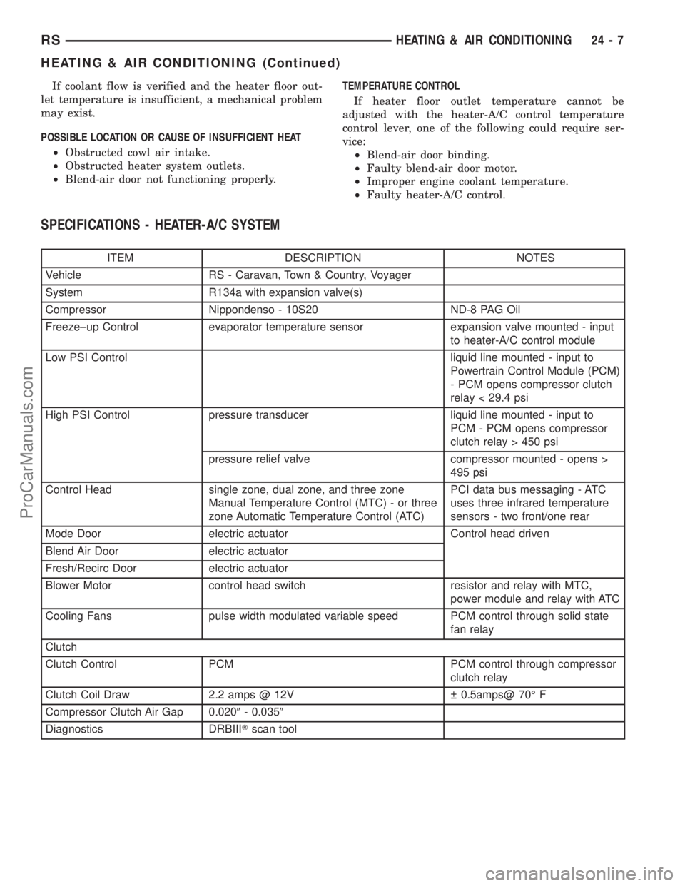
SPECIFICATIONS - HEATER-A/C SYSTEM
ITEM DESCRIPTION NOTES
Vehicle RS - Caravan, Town & Country, Voyager
System R134a with expansion valve(s)
Compressor Nippondenso - 10S20 ND-8 PAG Oil
Freeze±up Control evaporator temperature sensor expansion valve mounted - input
to heater-A/C control module
Low PSI Control liquid line mounted - input to
Powertrain Control Module (PCM)
- PCM opens compressor clutch
relay < 29.4 psi
High PSI Control pressure transducer liquid line mounted - input to
PCM - PCM opens compressor
clutch relay > 450 psi
pressure relief valve compressor mounted - opens >
495 psi
Control Head single zone, dual zone, and three zone
Manual Temperature Control (MTC) - or three
zone Automatic Temperature Control (ATC)PCI data bus messaging - ATC
uses three infrared temperature
sensors - two front/one rear
Mode Door electric actuator Control head driven
Blend Air Door electric actuator
Fresh/Recirc Door electric actuator
Blower Motor control head switch resistor and relay with MTC,
power module and relay with ATC
Cooling Fans pulse width modulated variable speed PCM control through solid state
fan relay
Clutch
Clutch Control PCM PCM control through compressor
clutch relay
Clutch Coil Draw 2.2 amps @ 12V 0.5amps@ 70É F
Compressor Clutch Air Gap 0.0209- 0.0359
Diagnostics DRBIIITscan tool
RSHEATING & AIR CONDITIONING24-7
HEATING & AIR CONDITIONING (Continued)
ProCarManuals.com
Page 2251 of 2399
CONTROLS - FRONT
TABLE OF CONTENTS
page page
A/C HEATER CONTROL
STANDARD PROCEDURE - HEATER-A/C
CONTROL CALIBRATION................8
REMOVAL.............................9
INSTALLATION..........................9
A/C PRESSURE TRANSDUCER
DESCRIPTION - A/C PRESSURE
TRANSDUCER.......................10
OPERATION...........................10
DIAGNOSIS AND TESTING - A/C PRESSURE
TRANSDUCER.......................10
REMOVAL.............................11
INSTALLATION.........................11
BLEND DOOR ACTUATOR
DESCRIPTION.........................11
OPERATION...........................11
REMOVAL.............................12
INSTALLATION.........................12
BLOWER MOTOR RELAY
DESCRIPTION.........................13
OPERATION...........................13
DIAGNOSIS AND TESTING - BLOWER
MOTOR RELAY.......................14
REMOVAL.............................14
INSTALLATION.........................14
BLOWER MOTOR RESISTOR
DESCRIPTION.........................15
OPERATION...........................15
DIAGNOSIS AND TESTING - BLOWER
MOTOR RESISTOR....................15
REMOVAL.............................16
INSTALLATION.........................16
COMPRESSOR CLUTCH
DESCRIPTION.........................16
OPERATION...........................17
STANDARD PROCEDURE
STANDARD PROCEDURE - COMPRESSOR
CLUTCH AIR GAP.....................17STANDARD PROCEDURE - COMPRESSOR
CLUTCH BREAK-IN....................17
REMOVAL.............................17
INSPECTION - COMPRESSOR CLUTCH/COIL . 18
INSTALLATION.........................19
COMPRESSOR CLUTCH COIL
DIAGNOSIS AND TESTING - COMPRESSOR
CLUTCH COIL........................20
COMPRESSOR CLUTCH RELAY
DESCRIPTION.........................21
OPERATION...........................21
DIAGNOSIS AND TESTING - COMPRESSOR
CLUTCH RELAY......................22
REMOVAL.............................22
INSTALLATION.........................22
EVAPORATOR TEMPERATURE SENSOR
DESCRIPTION.........................22
OPERATION...........................23
REMOVAL.............................23
INSTALLATION.........................23
INFRARED TEMPERATURE SENSOR
DESCRIPTION.........................24
OPERATION...........................24
MODE DOOR ACTUATOR
DESCRIPTION.........................24
OPERATION...........................25
REMOVAL.............................25
INSTALLATION.........................25
POWER MODULE
DESCRIPTION.........................26
OPERATION...........................26
REMOVAL.............................26
INSTALLATION.........................27
RECIRCULATION DOOR ACTUATOR
DESCRIPTION.........................27
OPERATION...........................27
REMOVAL.............................28
INSTALLATION.........................28
A/C HEATER CONTROL
STANDARD PROCEDURE - HEATER-A/C
CONTROL CALIBRATION
The heater-A/C control module must be recali-
brated each time an actuator motor or the control
module is replaced. If the vehicle is so equipped, the
calibration procedure also includes rear HVAC posi-
tions for each actuator motor.(1) Turn the ignition switch to the On position.
(2) Simultaneously depress and hold the Power
and Recirculation buttons on the heater-A/C control
for at least five seconds. The manual heater-A/C con-
trol power Light Emitting Diode (LED) and Recircu-
lation LED, or the Automatic Temperature Control
(ATC) heater-A/C control Delay and Recirculation
graphics will begin to flash when the calibration pro-
cedure has begun.
24 - 8 CONTROLS - FRONTRS
ProCarManuals.com