2002 DODGE RAM power steering
[x] Cancel search: power steeringPage 1020 of 2255
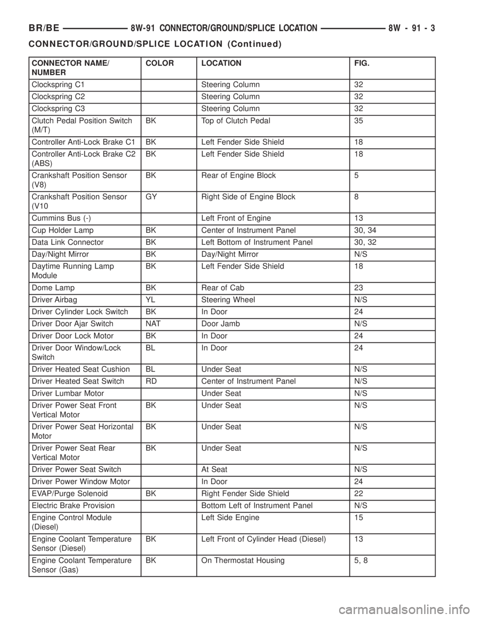
CONNECTOR NAME/
NUMBERCOLOR LOCATION FIG.
Clockspring C1 Steering Column 32
Clockspring C2 Steering Column 32
Clockspring C3 Steering Column 32
Clutch Pedal Position Switch
(M/T)BK Top of Clutch Pedal 35
Controller Anti-Lock Brake C1 BK Left Fender Side Shield 18
Controller Anti-Lock Brake C2
(ABS)BK Left Fender Side Shield 18
Crankshaft Position Sensor
(V8)BK Rear of Engine Block 5
Crankshaft Position Sensor
(V10GY Right Side of Engine Block 8
Cummins Bus (-) Left Front of Engine 13
Cup Holder Lamp BK Center of Instrument Panel 30, 34
Data Link Connector BK Left Bottom of Instrument Panel 30, 32
Day/Night Mirror BK Day/Night Mirror N/S
Daytime Running Lamp
ModuleBK Left Fender Side Shield 18
Dome Lamp BK Rear of Cab 23
Driver Airbag YL Steering Wheel N/S
Driver Cylinder Lock Switch BK In Door 24
Driver Door Ajar Switch NAT Door Jamb N/S
Driver Door Lock Motor BK In Door 24
Driver Door Window/Lock
SwitchBL In Door 24
Driver Heated Seat Cushion BL Under Seat N/S
Driver Heated Seat Switch RD Center of Instrument Panel N/S
Driver Lumbar Motor Under Seat N/S
Driver Power Seat Front
Vertical MotorBK Under Seat N/S
Driver Power Seat Horizontal
MotorBK Under Seat N/S
Driver Power Seat Rear
Vertical MotorBK Under Seat N/S
Driver Power Seat Switch At Seat N/S
Driver Power Window Motor In Door 24
EVAP/Purge Solenoid BK Right Fender Side Shield 22
Electric Brake Provision Bottom Left of Instrument Panel N/S
Engine Control Module
(Diesel)Left Side Engine 15
Engine Coolant Temperature
Sensor (Diesel)BK Left Front of Cylinder Head (Diesel) 13
Engine Coolant Temperature
Sensor (Gas)BK On Thermostat Housing 5, 8
BR/BE8W-91 CONNECTOR/GROUND/SPLICE LOCATION 8W - 91 - 3
CONNECTOR/GROUND/SPLICE LOCATION (Continued)
Page 1021 of 2255
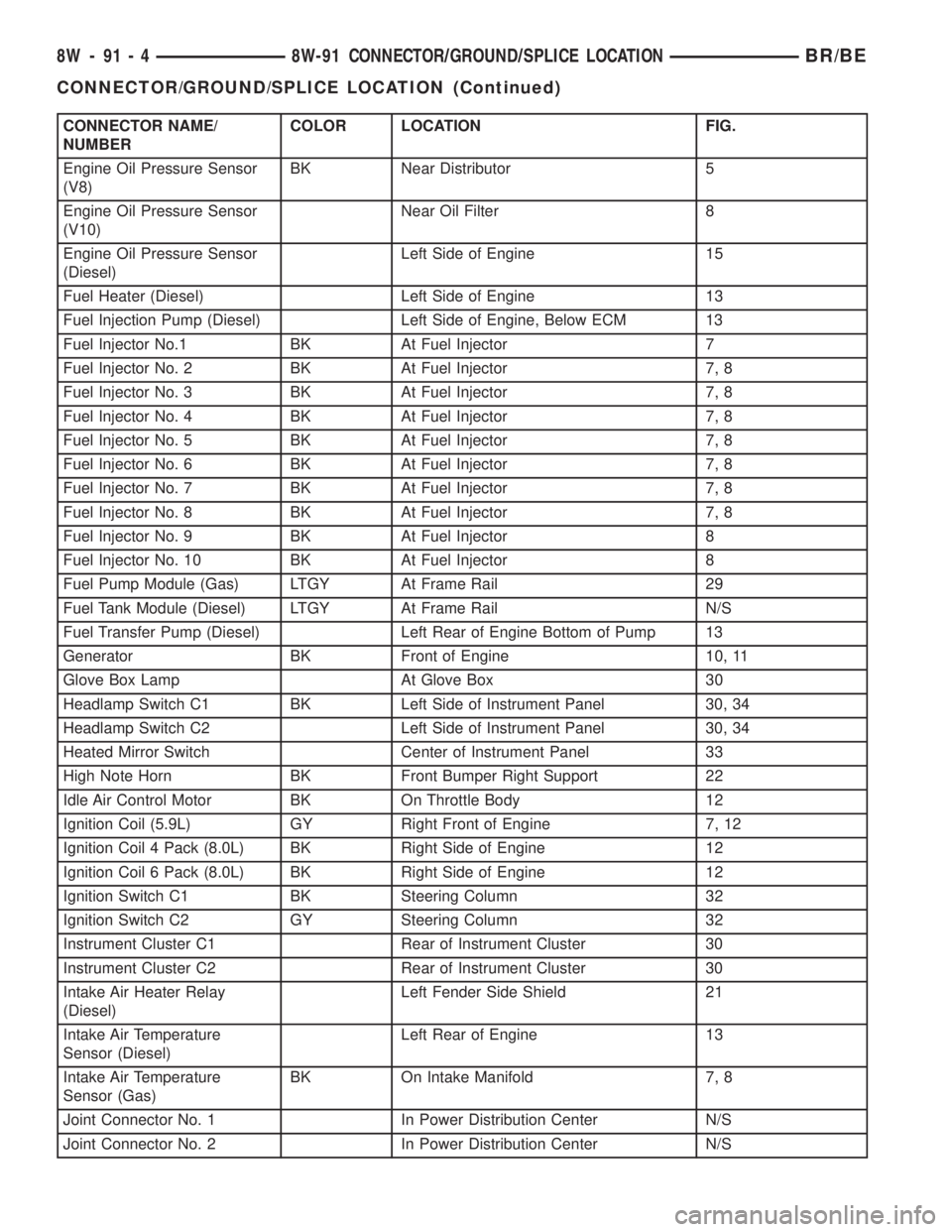
CONNECTOR NAME/
NUMBERCOLOR LOCATION FIG.
Engine Oil Pressure Sensor
(V8)BK Near Distributor 5
Engine Oil Pressure Sensor
(V10)Near Oil Filter 8
Engine Oil Pressure Sensor
(Diesel)Left Side of Engine 15
Fuel Heater (Diesel) Left Side of Engine 13
Fuel Injection Pump (Diesel) Left Side of Engine, Below ECM 13
Fuel Injector No.1 BK At Fuel Injector 7
Fuel Injector No. 2 BK At Fuel Injector 7, 8
Fuel Injector No. 3 BK At Fuel Injector 7, 8
Fuel Injector No. 4 BK At Fuel Injector 7, 8
Fuel Injector No. 5 BK At Fuel Injector 7, 8
Fuel Injector No. 6 BK At Fuel Injector 7, 8
Fuel Injector No. 7 BK At Fuel Injector 7, 8
Fuel Injector No. 8 BK At Fuel Injector 7, 8
Fuel Injector No. 9 BK At Fuel Injector 8
Fuel Injector No. 10 BK At Fuel Injector 8
Fuel Pump Module (Gas) LTGY At Frame Rail 29
Fuel Tank Module (Diesel) LTGY At Frame Rail N/S
Fuel Transfer Pump (Diesel) Left Rear of Engine Bottom of Pump 13
Generator BK Front of Engine 10, 11
Glove Box Lamp At Glove Box 30
Headlamp Switch C1 BK Left Side of Instrument Panel 30, 34
Headlamp Switch C2 Left Side of Instrument Panel 30, 34
Heated Mirror Switch Center of Instrument Panel 33
High Note Horn BK Front Bumper Right Support 22
Idle Air Control Motor BK On Throttle Body 12
Ignition Coil (5.9L) GY Right Front of Engine 7, 12
Ignition Coil 4 Pack (8.0L) BK Right Side of Engine 12
Ignition Coil 6 Pack (8.0L) BK Right Side of Engine 12
Ignition Switch C1 BK Steering Column 32
Ignition Switch C2 GY Steering Column 32
Instrument Cluster C1 Rear of Instrument Cluster 30
Instrument Cluster C2 Rear of Instrument Cluster 30
Intake Air Heater Relay
(Diesel)Left Fender Side Shield 21
Intake Air Temperature
Sensor (Diesel)Left Rear of Engine 13
Intake Air Temperature
Sensor (Gas)BK On Intake Manifold 7, 8
Joint Connector No. 1 In Power Distribution Center N/S
Joint Connector No. 2 In Power Distribution Center N/S
8W - 91 - 4 8W-91 CONNECTOR/GROUND/SPLICE LOCATIONBR/BE
CONNECTOR/GROUND/SPLICE LOCATION (Continued)
Page 1022 of 2255
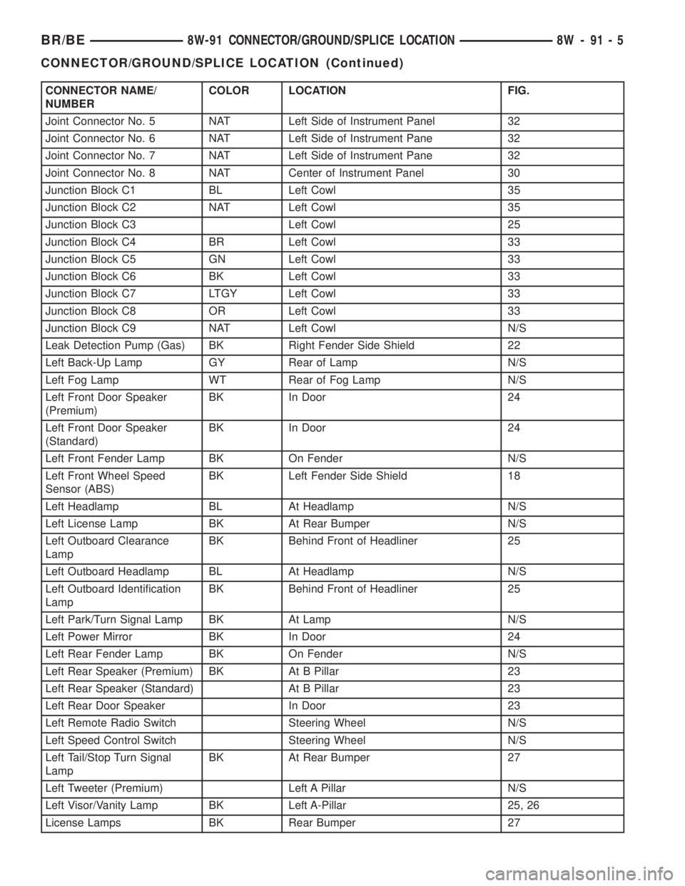
CONNECTOR NAME/
NUMBERCOLOR LOCATION FIG.
Joint Connector No. 5 NAT Left Side of Instrument Panel 32
Joint Connector No. 6 NAT Left Side of Instrument Pane 32
Joint Connector No. 7 NAT Left Side of Instrument Pane 32
Joint Connector No. 8 NAT Center of Instrument Panel 30
Junction Block C1 BL Left Cowl 35
Junction Block C2 NAT Left Cowl 35
Junction Block C3 Left Cowl 25
Junction Block C4 BR Left Cowl 33
Junction Block C5 GN Left Cowl 33
Junction Block C6 BK Left Cowl 33
Junction Block C7 LTGY Left Cowl 33
Junction Block C8 OR Left Cowl 33
Junction Block C9 NAT Left Cowl N/S
Leak Detection Pump (Gas) BK Right Fender Side Shield 22
Left Back-Up Lamp GY Rear of Lamp N/S
Left Fog Lamp WT Rear of Fog Lamp N/S
Left Front Door Speaker
(Premium)BK In Door 24
Left Front Door Speaker
(Standard)BK In Door 24
Left Front Fender Lamp BK On Fender N/S
Left Front Wheel Speed
Sensor (ABS)BK Left Fender Side Shield 18
Left Headlamp BL At Headlamp N/S
Left License Lamp BK At Rear Bumper N/S
Left Outboard Clearance
LampBK Behind Front of Headliner 25
Left Outboard Headlamp BL At Headlamp N/S
Left Outboard Identification
LampBK Behind Front of Headliner 25
Left Park/Turn Signal Lamp BK At Lamp N/S
Left Power Mirror BK In Door 24
Left Rear Fender Lamp BK On Fender N/S
Left Rear Speaker (Premium) BK At B Pillar 23
Left Rear Speaker (Standard) At B Pillar 23
Left Rear Door Speaker In Door 23
Left Remote Radio Switch Steering Wheel N/S
Left Speed Control Switch Steering Wheel N/S
Left Tail/Stop Turn Signal
LampBK At Rear Bumper 27
Left Tweeter (Premium) Left A Pillar N/S
Left Visor/Vanity Lamp BK Left A-Pillar 25, 26
License Lamps BK Rear Bumper 27
BR/BE8W-91 CONNECTOR/GROUND/SPLICE LOCATION 8W - 91 - 5
CONNECTOR/GROUND/SPLICE LOCATION (Continued)
Page 1025 of 2255
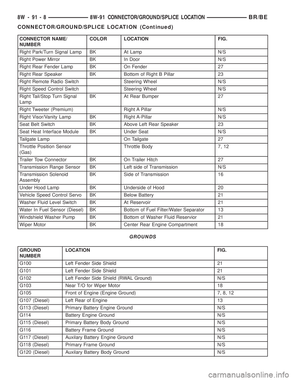
CONNECTOR NAME/
NUMBERCOLOR LOCATION FIG.
Right Park/Turn Signal Lamp BK At Lamp N/S
Right Power Mirror BK In Door N/S
Right Rear Fender Lamp BK On Fender 27
Right Rear Speaker BK Bottom of Right B Pillar 23
Right Remote Radio Switch Steering Wheel N/S
Right Speed Control Switch Steering Wheel N/S
Right Tail/Stop Turn Signal
LampBK At Rear Bumper 27
Right Tweeter (Premium) Right A Pillar N/S
Right Visor/Vanity Lamp BK Right A-Pillar N/S
Seat Belt Switch BK Above Left Rear Speaker 23
Seat Heat Interface Module BK Under Seat N/S
Tailgate Lamp On Tailgate 27
Throttle Position Sensor
(Gas)Throttle Body 7, 12
Trailer Tow Connector BK On Trailer Hitch 27
Transmission Range Sensor BK Left side of Transmission N/S
Transmission Solenoid
AssemblyBK Side of Transmission 16
Under Hood Lamp BK Underside of Hood 20
Vehicle Speed Control Servo BK Below Battery 21
Washer Fluid Level Switch BK At Reservoir 21
Water In Fuel Sensor (Diesel) BK Bottom of Fuel Filter/Water Separator 13
Windshield Washer Pump BK Bottom of Washer Fluid Reservior 21
Wiper Motor BK Center Rear Engine Compartment 18
GROUNDS
GROUND
NUMBERLOCATION FIG.
G100 Left Fender Side Shield 21
G101 Left Fender Side Shield 21
G102 Left Fender Side Shield (RWAL Ground) N/S
G103 Near T/O for Wiper Motor 18
G105 Front of Engine (Engine Ground) 7, 8, 12
G107 (Diesel) Left Rear of Engine 13
G113 (Diesel) Primary Battery Engine Ground N/S
G114 Battery Engine Ground N/S
G115 (Diesel) Primary Battery Body Ground N/S
G116 Battery Frame Ground N/S
G117 (Diesel) Auxilary Battery Engine Ground N/S
G118 (Diesel) Primary Frame Ground N/S
G120 (Diesel) Auxilary Battery Body Ground N/S
8W - 91 - 8 8W-91 CONNECTOR/GROUND/SPLICE LOCATIONBR/BE
CONNECTOR/GROUND/SPLICE LOCATION (Continued)
Page 1028 of 2255
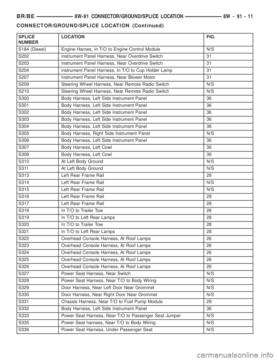
SPLICE
NUMBERLOCATION FIG.
S184 (Diesel) Engine Harnes, in T/O to Engine Control Module N/S
S202 Instrument Panel Harness, Near Overdrive Switch 31
S203 Instrument Panel Harness, Near Overdrive Switch 31
S204 instrument Panel Harness, In T/O to Cup Holder Lamp 31
S207 Instrument Panel Harness, Near Blower Motor 31
S209 Steering Wheel Harness, Near Remote Radio Switch N/S
S210 Steering Wheel Harness, Near Remote Radio Switch N/S
S300 Body Harness, Left Side Instrument Panel 36
S301 Body Harness, Left Side Instrument Panel 36
S302 Body Harness, Left Side Instrument Panel 36
S303 Body Harness, Left Side Instrument Panel 36
S304 Body Harness, Left Side Instrument Panel 36
S305 Body Harness, Right Side Instrument Panel N/S
S306 Body Harness, Left Side Instrument Panel 36
S307 Body Harness, Left Cowl 36
S308 Body Harness, Left Cowl 36
S310 At Left Body Ground N/S
S311 At Left Body Ground N/S
S313 Left Rear Frame Rail 28
S314 Left Rear Frame Rail N/S
S315 Left Rear Frame Rail N/S
S316 Left Rear Frame Rail 28
S317 Left Rear Frame Rail 28
S318 In T/O to Trailer Tow 28
S319 In T/O to Left Rear Lamps 28
S320 In T/O to Trailer Tow 28
S321 In T/O to Left Rear Lamps 28
S322 Overhead Console Harness, At Roof Lamps 26
S323 Overhead Console Harness, At Roof Lamps 26
S324 Overhead Console Harness, At Roof Lamps 26
S325 Overhead Console Harness, At Roof Lamps 26
S326 Overhead Console Harness, At Roof Lamps 26
S327 Power Seat Harness, Near Switch N/S
S328 Power Seat Harness, Near T/O to Body Wiring N/S
S329 Door Harness, Near Left Door Near Grommet N/S
S330 Door Harness, Near Right Door Near Grommet N/S
S331 Chassis Harness, Near T/O to Fuel Pump Module 28
S332 Body Harness, Left Side Instrument Panel 36
S333 Power Seat Harness, Near T/O to Passenger Seat Jumper N/S
S335 Power Seat harness, Near T/O to Body Wiring N/S
S336 Power Seat Harness, Under Passenger Seat N/S
BR/BE8W-91 CONNECTOR/GROUND/SPLICE LOCATION 8W - 91 - 11
CONNECTOR/GROUND/SPLICE LOCATION (Continued)
Page 1061 of 2255
tribution points for the electrical current required to
operate all of the many standard and optional facto-
ry-installed electrical and electronic powertrain,
chassis, safety, security, comfort and convenience sys-
tems. At the same time, the power distribution sys-
tem was designed to provide ready access to these
electrical distribution points for the vehicle techni-
cian to use when conducting diagnosis and repair of
faulty circuits. The power distribution system can
also prove useful for the sourcing of additional elec-
trical circuits that may be required to provide the
electrical current needed to operate many accessories
that the vehicle owner may choose to have installed
in the aftermarket.
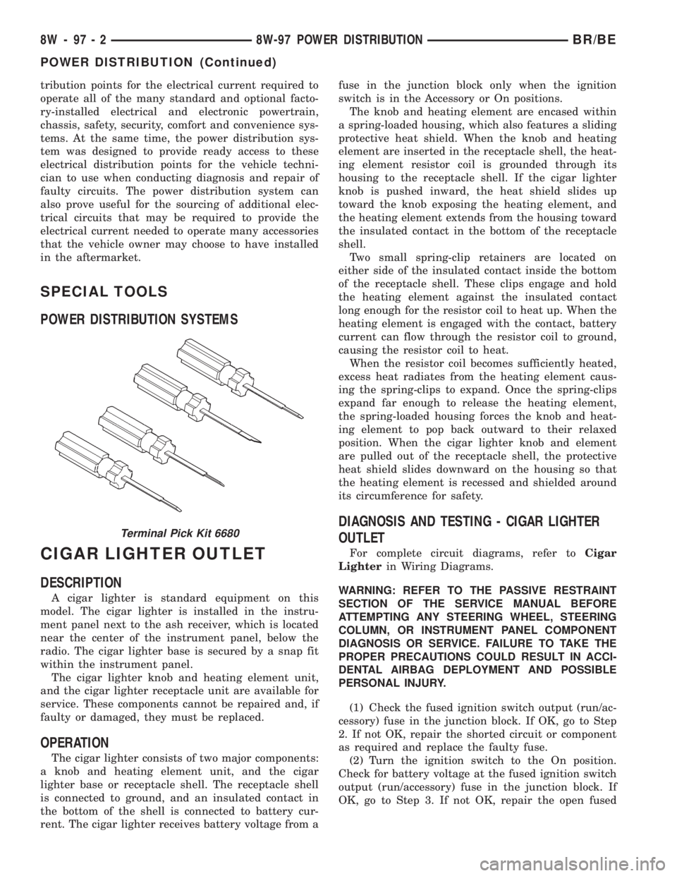
SPECIAL TOOLS
POWER DISTRIBUTION SYSTEMS
CIGAR LIGHTER OUTLET
DESCRIPTION
A cigar lighter is standard equipment on this
model. The cigar lighter is installed in the instru-
ment panel next to the ash receiver, which is located
near the center of the instrument panel, below the
radio. The cigar lighter base is secured by a snap fit
within the instrument panel.
The cigar lighter knob and heating element unit,
and the cigar lighter receptacle unit are available for
service. These components cannot be repaired and, if
faulty or damaged, they must be replaced.
OPERATION
The cigar lighter consists of two major components:
a knob and heating element unit, and the cigar
lighter base or receptacle shell. The receptacle shell
is connected to ground, and an insulated contact in
the bottom of the shell is connected to battery cur-
rent. The cigar lighter receives battery voltage from afuse in the junction block only when the ignition
switch is in the Accessory or On positions.
The knob and heating element are encased within
a spring-loaded housing, which also features a sliding
protective heat shield. When the knob and heating
element are inserted in the receptacle shell, the heat-
ing element resistor coil is grounded through its
housing to the receptacle shell. If the cigar lighter
knob is pushed inward, the heat shield slides up
toward the knob exposing the heating element, and
the heating element extends from the housing toward
the insulated contact in the bottom of the receptacle
shell.
Two small spring-clip retainers are located on
either side of the insulated contact inside the bottom
of the receptacle shell. These clips engage and hold
the heating element against the insulated contact
long enough for the resistor coil to heat up. When the
heating element is engaged with the contact, battery
current can flow through the resistor coil to ground,
causing the resistor coil to heat.
When the resistor coil becomes sufficiently heated,
excess heat radiates from the heating element caus-
ing the spring-clips to expand. Once the spring-clips
expand far enough to release the heating element,
the spring-loaded housing forces the knob and heat-
ing element to pop back outward to their relaxed
position. When the cigar lighter knob and element
are pulled out of the receptacle shell, the protective
heat shield slides downward on the housing so that
the heating element is recessed and shielded around
its circumference for safety.
DIAGNOSIS AND TESTING - CIGAR LIGHTER
OUTLET
For complete circuit diagrams, refer toCigar
Lighterin Wiring Diagrams.
WARNING: REFER TO THE PASSIVE RESTRAINT
SECTION OF THE SERVICE MANUAL BEFORE
ATTEMPTING ANY STEERING WHEEL, STEERING
COLUMN, OR INSTRUMENT PANEL COMPONENT
DIAGNOSIS OR SERVICE. FAILURE TO TAKE THE
PROPER PRECAUTIONS COULD RESULT IN ACCI-
DENTAL AIRBAG DEPLOYMENT AND POSSIBLE
PERSONAL INJURY.
(1) Check the fused ignition switch output (run/ac-
cessory) fuse in the junction block. If OK, go to Step
2. If not OK, repair the shorted circuit or component
as required and replace the faulty fuse.
(2) Turn the ignition switch to the On position.
Check for battery voltage at the fused ignition switch
output (run/accessory) fuse in the junction block. If
OK, go to Step 3. If not OK, repair the open fused
Terminal Pick Kit 6680
8W - 97 - 2 8W-97 POWER DISTRIBUTIONBR/BE
POWER DISTRIBUTION (Continued)
Page 1066 of 2255
tor between many of the engine compartment, instru-
ment panel, and body wire harnesses. The JB houses
up to nineteen blade-type fuses (two standard-type
and seventeen mini-type), up to two blade-type auto-
matic resetting circuit breakers, the electronic combi-
nation turn signal and hazard warning flasher, and
one International Standards Organization (ISO)
micro-relay.
The molded plastic JB housing has integral mount-
ing brackets that are secured with two screws to the
left instrument panel end bracket. The left end of the
instrument panel cover has a snap-fit fuse access
panel that can be removed for service of the JB. A
fuse puller and spare fuse holders are located on the
back of the fuse access cover, as well as an adhesive-
backed fuse layout map to ensure proper fuse identi-
fication.
The JB unit cannot be repaired and is only ser-
viced as an assembly. If any internal circuit or the JB
housing is faulty or damaged, the entire JB unit
must be replaced.
OPERATION
All of the circuits entering and leaving the JB do
so through up to nine wire harness connectors, which
are connected to the JB through integral connector
receptacles molded into the JB housing. Internal con-
nection of all of the JB circuits is accomplished by an
intricate combination of hard wiring and bus bars.
Refer toWiring Diagramsfor the location of com-
plete JB circuit diagrams.
DIAGNOSIS AND TESTING - JUNCTION BLOCK
The junction block does not incorporate any self
diagnostic capability. Most of the electrical circuits
incorporated into the vehicle must pass through the
junction block at one point or another. The most effi-
cient means of diagnosing a suspected junction block
problem involves a simple continuity tester or ohm
meter. Using the Wiring Diagrams as a guide trace
the problem circuit to the proper junction block cav-
ity and test all circuits in the effected circuit for
proper continuity. A open or high resistance circuit is
a sign of a problem. Some other possible junction
block problems to look for are:
²Loose fuse receptacle terminals.
²Loose relay / circuit breaker receptacle termi-
nals.
²Bent or distorted electrical circuit pins.
²Incorrect size fuse installed in junction block
fuse cavity.
²Dark areas identifying a source of excess heat.
²Defective fuse, relay or circuit breaker installed
in junction block cavity.
REMOVAL
(1) Disconnect and isolate the battery negative
cable.
(2) Remove the fuse access bezel from the instru-
ment panel.
(3) Remove the steering column cover (Refer to 23
- BODY/INSTRUMENT PANEL/STEERING COL-
UMN OPENING COVER - REMOVAL).
(4) Remove the hood release handle retaining
screws and position the handle assembly out of the
way.
(5) Remove the lower knee blocker from the instru-
ment panel.
(6) Pull drivers side carpet down, out of the way.
(7) Remove the parking brake switch connector,
release linkage and retaining fasteners and position
the assembly out the drivers door opening.
(8) Remove the electrical ground connections,
located behind park brake mounting location.
(9) Remove the two junction block retaining
screws. To access the upper retaining screw a 15 inch
long #2 Phillips screwdriver will be required. Access
the upper screw through hole in dash support brace.
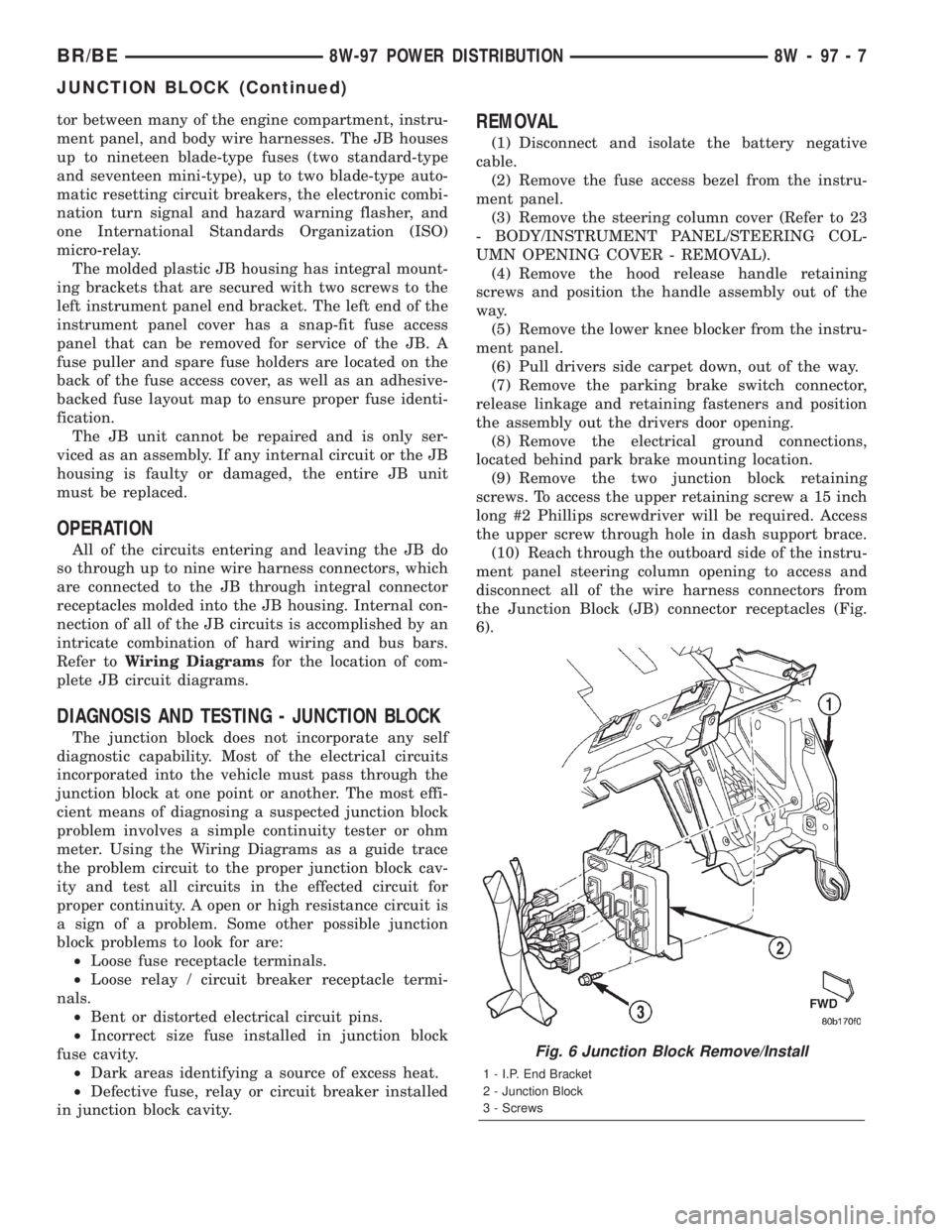
(10) Reach through the outboard side of the instru-
ment panel steering column opening to access and
disconnect all of the wire harness connectors from
the Junction Block (JB) connector receptacles (Fig.
6).
Fig. 6 Junction Block Remove/Install
1 - I.P. End Bracket
2 - Junction Block
3 - Screws
BR/BE8W-97 POWER DISTRIBUTION 8W - 97 - 7
JUNCTION BLOCK (Continued)
Page 1067 of 2255
(11) Remove the junction block from under the
instrument panel.
INSTALLATION
NOTE: If the Junction Block (JB) is being replaced
with a new unit, be certain to transfer each of the
fuses, circuit breakers and relays from the faulty JB
to the proper cavities of the replacement JB. Refer
to Junction Block in the index of this service man-
ual for the location of complete circuit diagrams
and cavity assignments for the JB.
(1) Position the junction block under the instru-
ment panel.
(2) Connect all of the wire harness connectors on
the Junction Block (JB) connector receptacles.
(3) Install the two junction block retaining screws.
(4) Install the electrical ground connections,
located behind park brake mounting location.
(5) Install the parking brake switch connector,
release linkage and retaining fasteners.
(6) Reposition drivers side carpet.
(7) Install the lower knee blocker on the instru-
ment panel.
(8) Install the hood release handle retaining
screws.
(9) Install the steering column cover.
(10) Install the fuse access bezel on the instrument
panel.
(11) Connect the battery negative cable.
POWER DISTRIBUTION
CENTER
DESCRIPTION
All of the electrical current distributed throughout
this vehicle is directed through the standard equip-
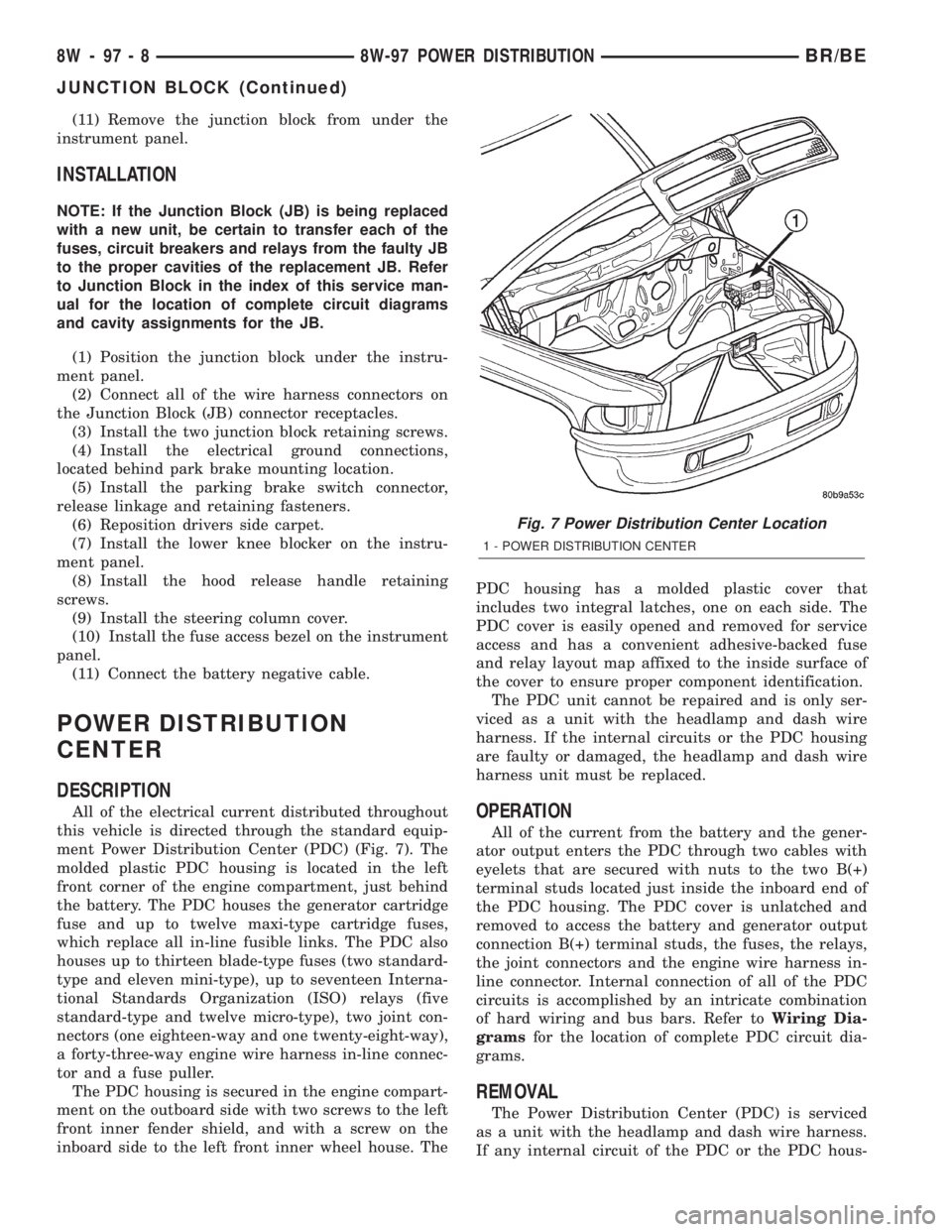
ment Power Distribution Center (PDC) (Fig. 7). The
molded plastic PDC housing is located in the left
front corner of the engine compartment, just behind
the battery. The PDC houses the generator cartridge
fuse and up to twelve maxi-type cartridge fuses,
which replace all in-line fusible links. The PDC also
houses up to thirteen blade-type fuses (two standard-
type and eleven mini-type), up to seventeen Interna-
tional Standards Organization (ISO) relays (five
standard-type and twelve micro-type), two joint con-
nectors (one eighteen-way and one twenty-eight-way),
a forty-three-way engine wire harness in-line connec-
tor and a fuse puller.
The PDC housing is secured in the engine compart-
ment on the outboard side with two screws to the left
front inner fender shield, and with a screw on the
inboard side to the left front inner wheel house. ThePDC housing has a molded plastic cover that
includes two integral latches, one on each side. The
PDC cover is easily opened and removed for service
access and has a convenient adhesive-backed fuse
and relay layout map affixed to the inside surface of
the cover to ensure proper component identification.
The PDC unit cannot be repaired and is only ser-
viced as a unit with the headlamp and dash wire
harness. If the internal circuits or the PDC housing
are faulty or damaged, the headlamp and dash wire
harness unit must be replaced.OPERATION
All of the current from the battery and the gener-
ator output enters the PDC through two cables with
eyelets that are secured with nuts to the two B(+)
terminal studs located just inside the inboard end of
the PDC housing. The PDC cover is unlatched and
removed to access the battery and generator output
connection B(+) terminal studs, the fuses, the relays,
the joint connectors and the engine wire harness in-
line connector. Internal connection of all of the PDC
circuits is accomplished by an intricate combination
of hard wiring and bus bars. Refer toWiring Dia-
gramsfor the location of complete PDC circuit dia-
grams.
REMOVAL
The Power Distribution Center (PDC) is serviced
as a unit with the headlamp and dash wire harness.
If any internal circuit of the PDC or the PDC hous-
Fig. 7 Power Distribution Center Location
1 - POWER DISTRIBUTION CENTER
8W - 97 - 8 8W-97 POWER DISTRIBUTIONBR/BE
JUNCTION BLOCK (Continued)