2002 DODGE RAM gas type
[x] Cancel search: gas typePage 417 of 2255
(2) Disconnect sensor pigtail harness from engine
wire harness.
(3) Pry sensor straight up from battery tray
mounting hole.
INSTALLATION
The battery temperature sensor is located under
the vehicle battery (Fig. 1) and is attached (snapped
into) a mounting hole on battery tray. On models
equipped with a diesel engine (dual batteries), only
one sensor is used. The sensor is located under the
battery on drivers side of vehicle.
(1) Feed pigtail harness through mounting hole in
top of battery tray and press sensor into top of tray
(snaps in).
(2) Connect pigtail harness.
(3) Install battery. Refer to 8A, Battery for proce-
dures.
GENERATOR
DESCRIPTION
The generator is belt-driven by the engine using a
serpentine type drive belt. It is serviced only as a
complete assembly. If the generator fails for any rea-
son, the entire assembly must be replaced.
OPERATION
As the energized rotor begins to rotate within the
generator, the spinning magnetic field induces a cur-
rent into the windings of the stator coil. Once the
generator begins producing sufficient current, it also
provides the current needed to energize the rotor.
The Y type stator winding connections deliver the
induced alternating current to 3 positive and 3 neg-
ative diodes for rectification. From the diodes, recti-
fied direct current is delivered to the vehicle
electrical system through the generator battery ter-
minal.
Although the generators appear the same exter-
nally, different generators with different output rat-
ings are used on this vehicle. Be certain that the
replacement generator has the same output rating
and part number as the original unit. Refer to Gen-
erator Ratings in the Specifications section at the
back of this group for amperage ratings and part
numbers.
Noise emitting from the generator may be caused
by: worn, loose or defective bearings; a loose or defec-
tive drive pulley; incorrect, worn, damaged or misad-
justed fan drive belt; loose mounting bolts; a
misaligned drive pulley or a defective stator or diode.
REMOVAL
WARNING: DISCONNECT NEGATIVE CABLE FROM
BATTERY BEFORE REMOVING BATTERY OUTPUT
WIRE (B+ WIRE) FROM GENERATOR. FAILURE TO
DO SO CAN RESULT IN INJURY OR DAMAGE TO
ELECTRICAL SYSTEM.
(1) Disconnect negative battery cable at battery.
Diesel Engines: Disconnect both negative battery
cables at both batteries.
(2) Remove generator drive belt. Refer to 7, Cool-
ing System for procedure.
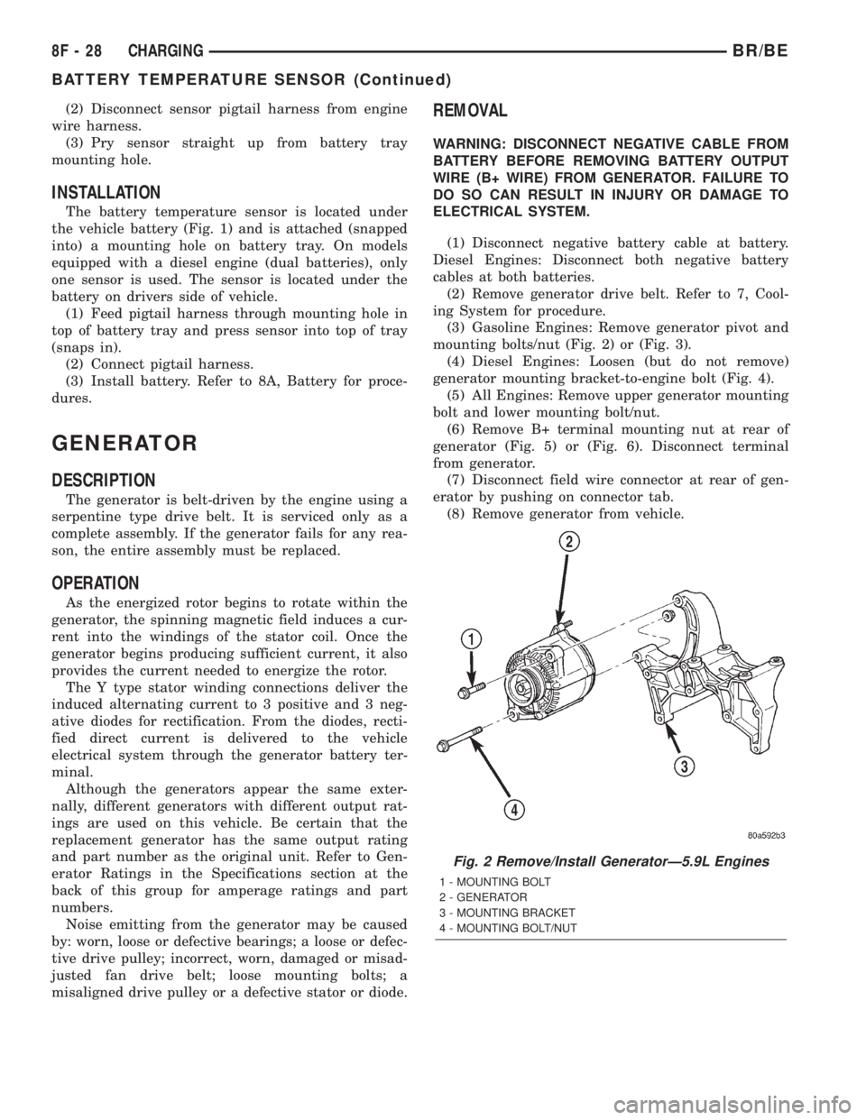
(3) Gasoline Engines: Remove generator pivot and
mounting bolts/nut (Fig. 2) or (Fig. 3).
(4) Diesel Engines: Loosen (but do not remove)
generator mounting bracket-to-engine bolt (Fig. 4).
(5) All Engines: Remove upper generator mounting
bolt and lower mounting bolt/nut.
(6) Remove B+ terminal mounting nut at rear of
generator (Fig. 5) or (Fig. 6). Disconnect terminal
from generator.
(7) Disconnect field wire connector at rear of gen-
erator by pushing on connector tab.
(8) Remove generator from vehicle.
Fig. 2 Remove/Install GeneratorÐ5.9L Engines
1 - MOUNTING BOLT
2 - GENERATOR
3 - MOUNTING BRACKET
4 - MOUNTING BOLT/NUT
8F - 28 CHARGINGBR/BE
BATTERY TEMPERATURE SENSOR (Continued)
Page 425 of 2255
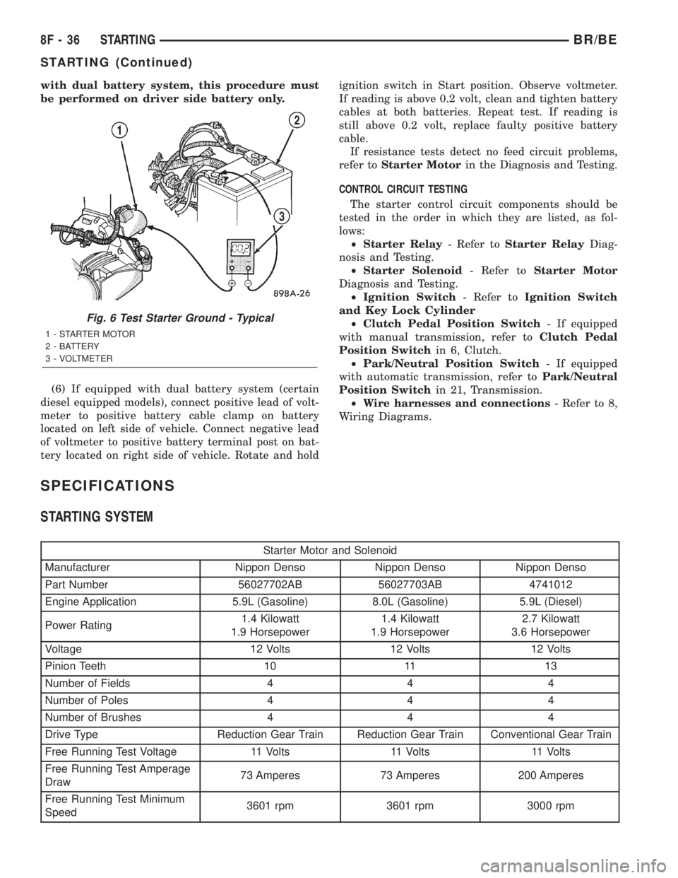
with dual battery system, this procedure must
be performed on driver side battery only.
(6) If equipped with dual battery system (certain
diesel equipped models), connect positive lead of volt-
meter to positive battery cable clamp on battery
located on left side of vehicle. Connect negative lead
of voltmeter to positive battery terminal post on bat-
tery located on right side of vehicle. Rotate and holdignition switch in Start position. Observe voltmeter.
If reading is above 0.2 volt, clean and tighten battery
cables at both batteries. Repeat test. If reading is
still above 0.2 volt, replace faulty positive battery
cable.
If resistance tests detect no feed circuit problems,
refer toStarter Motorin the Diagnosis and Testing.
CONTROL CIRCUIT TESTING
The starter control circuit components should be
tested in the order in which they are listed, as fol-
lows:
²Starter Relay- Refer toStarter RelayDiag-
nosis and Testing.
²Starter Solenoid- Refer toStarter Motor
Diagnosis and Testing.
²Ignition Switch- Refer toIgnition Switch
and Key Lock Cylinder
²Clutch Pedal Position Switch- If equipped
with manual transmission, refer toClutch Pedal
Position Switchin 6, Clutch.
²Park/Neutral Position Switch- If equipped
with automatic transmission, refer toPark/Neutral
Position Switchin 21, Transmission.
²Wire harnesses and connections- Refer to 8,
Wiring Diagrams.
SPECIFICATIONS
STARTING SYSTEM
Starter Motor and Solenoid
Manufacturer Nippon Denso Nippon Denso Nippon Denso
Part Number 56027702AB 56027703AB 4741012
Engine Application 5.9L (Gasoline) 8.0L (Gasoline) 5.9L (Diesel)
Power Rating1.4 Kilowatt
1.9 Horsepower1.4 Kilowatt
1.9 Horsepower2.7 Kilowatt
3.6 Horsepower
Voltage 12 Volts 12 Volts 12 Volts
Pinion Teeth 10 11 13
Number of Fields 4 4 4
Number of Poles 4 4 4
Number of Brushes 4 4 4
Drive Type Reduction Gear Train Reduction Gear Train Conventional Gear Train
Free Running Test Voltage 11 Volts 11 Volts 11 Volts
Free Running Test Amperage
Draw73 Amperes 73 Amperes 200 Amperes
Free Running Test Minimum
Speed3601 rpm 3601 rpm 3000 rpm
Fig. 6 Test Starter Ground - Typical
1 - STARTER MOTOR
2 - BATTERY
3 - VOLTMETER
8F - 36 STARTINGBR/BE
STARTING (Continued)
Page 472 of 2255
IGNITION COIL
DESCRIPTION
DESCRIPTION - 5.9L
A single ignition coil is used. The coil is not oil
filled. The coil windings are embedded in an epoxy
compound. This provides heat and vibration resis-
tance that allows the coil to be mounted on the
engine.
DESCRIPTION - 8.0L
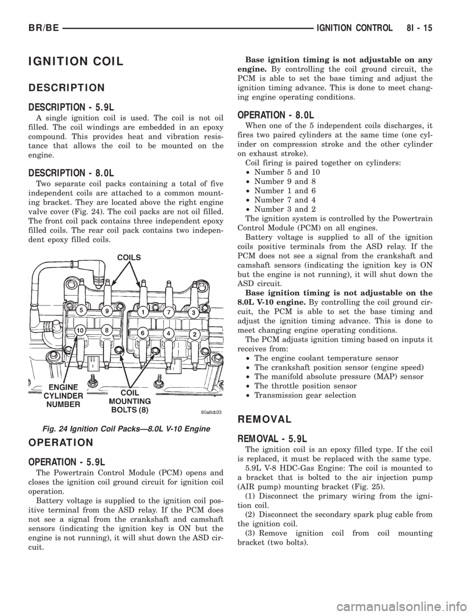
Two separate coil packs containing a total of five
independent coils are attached to a common mount-
ing bracket. They are located above the right engine
valve cover (Fig. 24). The coil packs are not oil filled.
The front coil pack contains three independent epoxy
filled coils. The rear coil pack contains two indepen-
dent epoxy filled coils.
OPERATION
OPERATION - 5.9L
The Powertrain Control Module (PCM) opens and
closes the ignition coil ground circuit for ignition coil
operation.
Battery voltage is supplied to the ignition coil pos-
itive terminal from the ASD relay. If the PCM does
not see a signal from the crankshaft and camshaft
sensors (indicating the ignition key is ON but the
engine is not running), it will shut down the ASD cir-
cuit.Base ignition timing is not adjustable on any
engine.By controlling the coil ground circuit, the
PCM is able to set the base timing and adjust the
ignition timing advance. This is done to meet chang-
ing engine operating conditions.
OPERATION - 8.0L
When one of the 5 independent coils discharges, it
fires two paired cylinders at the same time (one cyl-
inder on compression stroke and the other cylinder
on exhaust stroke).
Coil firing is paired together on cylinders:
²Number 5 and 10
²Number 9 and 8
²Number 1 and 6
²Number 7 and 4
²Number 3 and 2
The ignition system is controlled by the Powertrain
Control Module (PCM) on all engines.
Battery voltage is supplied to all of the ignition
coils positive terminals from the ASD relay. If the
PCM does not see a signal from the crankshaft and
camshaft sensors (indicating the ignition key is ON
but the engine is not running), it will shut down the
ASD circuit.
Base ignition timing is not adjustable on the
8.0L V-10 engine.By controlling the coil ground cir-
cuit, the PCM is able to set the base timing and
adjust the ignition timing advance. This is done to
meet changing engine operating conditions.
The PCM adjusts ignition timing based on inputs it
receives from:
²The engine coolant temperature sensor
²The crankshaft position sensor (engine speed)
²The manifold absolute pressure (MAP) sensor
²The throttle position sensor
²Transmission gear selection
REMOVAL
REMOVAL - 5.9L
The ignition coil is an epoxy filled type. If the coil
is replaced, it must be replaced with the same type.
5.9L V-8 HDC-Gas Engine: The coil is mounted to
a bracket that is bolted to the air injection pump
(AIR pump) mounting bracket (Fig. 25).
(1) Disconnect the primary wiring from the igni-
tion coil.
(2) Disconnect the secondary spark plug cable from
the ignition coil.
(3) Remove ignition coil from coil mounting
bracket (two bolts).
Fig. 24 Ignition Coil PacksÐ8.0L V-10 Engine
BR/BEIGNITION CONTROL 8I - 15
Page 473 of 2255
REMOVAL - 8.0L
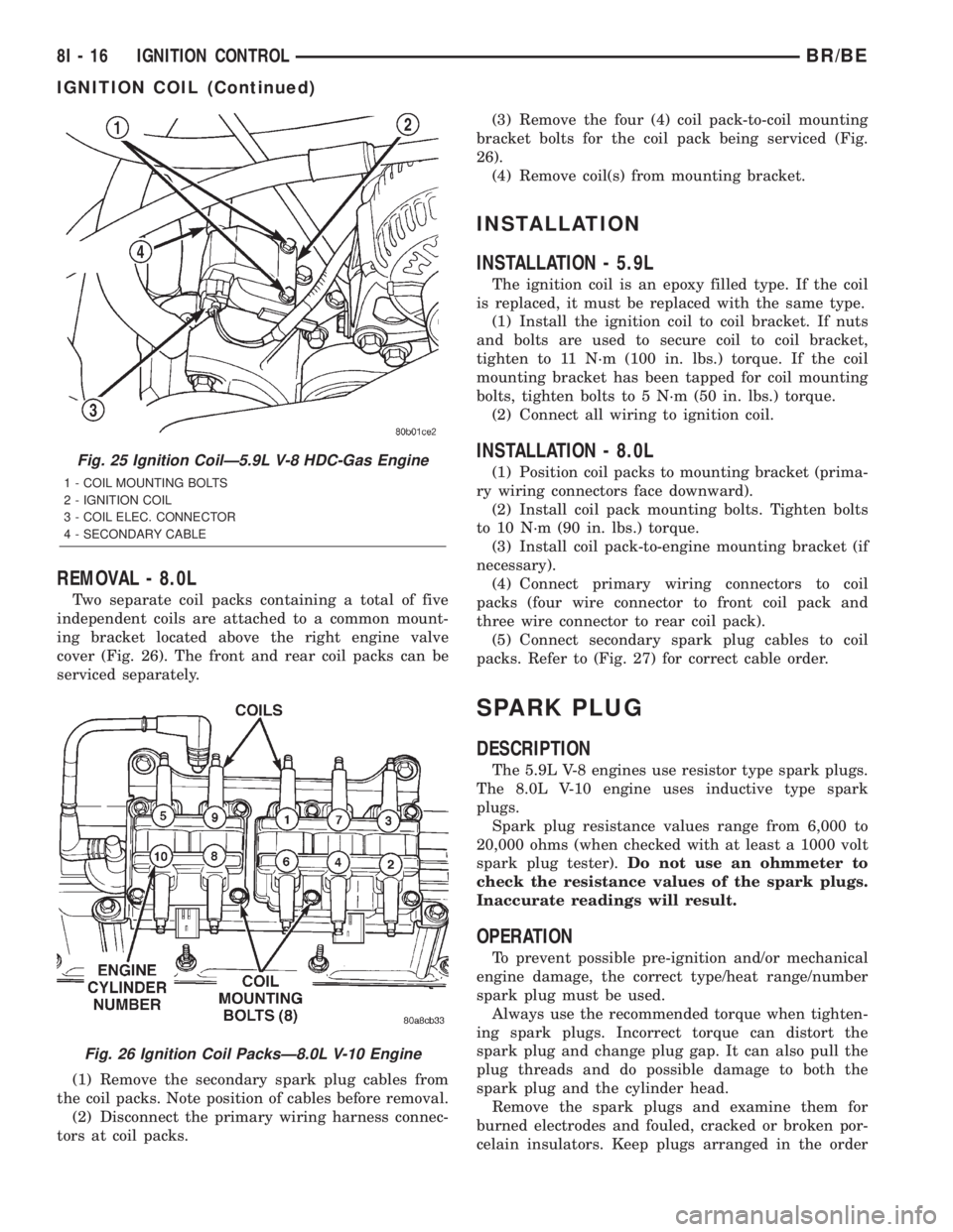
Two separate coil packs containing a total of five
independent coils are attached to a common mount-
ing bracket located above the right engine valve
cover (Fig. 26). The front and rear coil packs can be
serviced separately.
(1) Remove the secondary spark plug cables from
the coil packs. Note position of cables before removal.
(2) Disconnect the primary wiring harness connec-
tors at coil packs.(3) Remove the four (4) coil pack-to-coil mounting
bracket bolts for the coil pack being serviced (Fig.
26).
(4) Remove coil(s) from mounting bracket.
INSTALLATION
INSTALLATION - 5.9L
The ignition coil is an epoxy filled type. If the coil
is replaced, it must be replaced with the same type.
(1) Install the ignition coil to coil bracket. If nuts
and bolts are used to secure coil to coil bracket,
tighten to 11 N´m (100 in. lbs.) torque. If the coil
mounting bracket has been tapped for coil mounting
bolts, tighten bolts to 5 N´m (50 in. lbs.) torque.
(2) Connect all wiring to ignition coil.
INSTALLATION - 8.0L
(1) Position coil packs to mounting bracket (prima-
ry wiring connectors face downward).
(2) Install coil pack mounting bolts. Tighten bolts
to 10 N´m (90 in. lbs.) torque.
(3) Install coil pack-to-engine mounting bracket (if
necessary).
(4) Connect primary wiring connectors to coil
packs (four wire connector to front coil pack and
three wire connector to rear coil pack).
(5) Connect secondary spark plug cables to coil
packs. Refer to (Fig. 27) for correct cable order.
SPARK PLUG
DESCRIPTION
The 5.9L V-8 engines use resistor type spark plugs.
The 8.0L V-10 engine uses inductive type spark
plugs.
Spark plug resistance values range from 6,000 to
20,000 ohms (when checked with at least a 1000 volt
spark plug tester).Do not use an ohmmeter to
check the resistance values of the spark plugs.
Inaccurate readings will result.
OPERATION
To prevent possible pre-ignition and/or mechanical
engine damage, the correct type/heat range/number
spark plug must be used.
Always use the recommended torque when tighten-
ing spark plugs. Incorrect torque can distort the
spark plug and change plug gap. It can also pull the
plug threads and do possible damage to both the
spark plug and the cylinder head.
Remove the spark plugs and examine them for
burned electrodes and fouled, cracked or broken por-
celain insulators. Keep plugs arranged in the order
Fig. 25 Ignition CoilÐ5.9L V-8 HDC-Gas Engine
1 - COIL MOUNTING BOLTS
2 - IGNITION COIL
3 - COIL ELEC. CONNECTOR
4 - SECONDARY CABLE
Fig. 26 Ignition Coil PacksÐ8.0L V-10 Engine
8I - 16 IGNITION CONTROLBR/BE
IGNITION COIL (Continued)
Page 596 of 2255

circumstances necessitate that a child, or an adult
with certain medical conditions be placed in the front
passenger seating position. Refer to the owner's man-
ual in the vehicle glove box for specific recommenda-
tions concerning the specific circumstances where the
passenger airbag on/off switch should be used to dis-
able the passenger airbag.
Deployment of the airbags depends upon the angle
and severity of the impact. The airbag system is
designed to deploy upon a frontal impact within a
thirty degree angle from either side of the vehicle
center line. Deployment is not based upon vehicle
speed; rather, deployment is based upon the rate of
deceleration as measured by the forces of gravity (G
force) upon the airbag system impact sensor, which is
integral to the ACM. When a frontal impact is severe
enough, the microprocessor in the ACM signals the
inflator units of both airbag modules to deploy the
airbags. During a frontal vehicle impact, the knee
blockers work in concert with properly fastened and
adjusted seat belts to restrain both the driver and
the front seat passenger in the proper position for an
airbag deployment. The knee blockers also absorb
and distribute the crash energy from the driver and
the front seat passenger to the structure of the
instrument panel.
Typically, the driver and front seat passenger recall
more about the events preceding and following a col-
lision than they have of the airbag deployment itself.
This is because the airbag deployment and deflation
occur so rapidly. In a typical 48 kilometer-per-hour
(30 mile-per-hour) barrier impact, from the moment
of impact until both airbags are fully inflated takes
about 40 milliseconds. Within one to two seconds
from the moment of impact, both airbags are almost
entirely deflated. The times cited for these events are
approximations, which apply only to a barrier impact
at the given speed. Actual times will vary somewhat,
depending upon the vehicle speed, impact angle,
severity of the impact, and the type of collision.
When the ACM monitors a problem in any of the
airbag system circuits or components, it stores a
fault code or Diagnostic Trouble Code (DTC) in its
memory circuit and sends an electronic message to
the EMIC to turn on the airbag indicator. Proper
testing of the airbag system components, the
Chrysler Collision Detection (CCD) data bus, the
data bus message inputs to and outputs from the
EMIC or the ACM, as well as the retrieval or erasure
of a DTC from the ACM requires the use of a
DRBIIItscan tool. Refer to the appropriate diagnos-
tic information.
See the owner's manual in the vehicle glove box for
more information on the features, use and operation
of all of the factory-installed passenger restraints,
including the airbag system.WARNING
WARNING: THE AIRBAG SYSTEM IS A SENSITIVE,
COMPLEX ELECTROMECHANICAL UNIT. BEFORE
ATTEMPTING TO DIAGNOSE OR SERVICE ANY AIR-
BAG SYSTEM OR RELATED STEERING WHEEL,
STEERING COLUMN, OR INSTRUMENT PANEL
COMPONENTS YOU MUST FIRST DISCONNECT
AND ISOLATE THE BATTERY NEGATIVE (GROUND)
CABLE. THEN WAIT TWO MINUTES FOR THE SYS-
TEM CAPACITOR TO DISCHARGE BEFORE FUR-
THER SYSTEM SERVICE. THIS IS THE ONLY SURE
WAY TO DISABLE THE AIRBAG SYSTEM. FAILURE
TO DO THIS COULD RESULT IN ACCIDENTAL AIR-
BAG DEPLOYMENT AND POSSIBLE PERSONAL
INJURY.
WARNING: THE DRIVER AIRBAG INFLATOR UNIT
CONTAINS SODIUM AZIDE AND POTASSIUM
NITRATE. THESE MATERIALS ARE POISONOUS
AND EXTREMELY FLAMMABLE. CONTACT WITH
ACID, WATER, OR HEAVY METALS MAY PRODUCE
HARMFUL AND IRRITATING GASES (SODIUM
HYDROXIDE IS FORMED IN THE PRESENCE OF
MOISTURE) OR COMBUSTIBLE COMPOUNDS. THE
PASSENGER AIRBAG UNIT CONTAINS ARGON GAS
PRESSURIZED TO OVER 2500 PSI. DO NOT
ATTEMPT TO DISMANTLE AN AIRBAG UNIT OR
TAMPER WITH ITS INFLATOR. DO NOT PUNCTURE,
INCINERATE, OR BRING INTO CONTACT WITH
ELECTRICITY. DO NOT STORE AT TEMPERATURES
EXCEEDING 93É C (200É F).
WARNING: REPLACE AIRBAG SYSTEM COMPO-
NENTS ONLY WITH PARTS SPECIFIED IN THE
DAIMLERCHRYSLER MOPAR PARTS CATALOG.
SUBSTITUTE PARTS MAY APPEAR INTERCHANGE-
ABLE, BUT INTERNAL DIFFERENCES MAY RESULT
IN INFERIOR OCCUPANT PROTECTION.
WARNING: THE FASTENERS, SCREWS, AND
BOLTS ORIGINALLY USED FOR THE AIRBAG SYS-
TEM COMPONENTS HAVE SPECIAL COATINGS
AND ARE SPECIFICALLY DESIGNED FOR THE AIR-
BAG SYSTEM. THEY MUST NEVER BE REPLACED
WITH ANY SUBSTITUTES. ANY TIME A NEW FAS-
TENER IS NEEDED, REPLACE IT WITH THE COR-
RECT FASTENERS PROVIDED IN THE SERVICE
PACKAGE OR SPECIFIED IN THE
DAIMLERCHRYSLER MOPAR PARTS CATALOG.
BR/BERESTRAINTS 8O - 3
RESTRAINTS (Continued)
Page 607 of 2255

DRIVER AIRBAG
DESCRIPTION
The driver airbag protective trim cover is the most
visible part of the driver airbag. The airbag used in
this model is a Next Generation-type that complies
with revised federal airbag standards to deploy with
less force than those used in some prior models. The
driver airbag is located in the center of the steering
wheel, where it is secured with two screws to the
steering wheel armature. Concealed beneath the
driver airbag trim cover are the horn switch, the
folded airbag cushion, the airbag retainer or housing,
the airbag inflator, and the retainers that secure the
trim cover to the airbag housing. The resistive mem-
brane-type horn switch is secured with heat stakes to
the inside surface of the airbag trim cover, between
the trim cover and the folded airbag cushion. The air-
bag inflator is a conventional pyrotechnic-type unit
that is secured with nuts to four studs on the back of
the stamped metal airbag housing.
The driver airbag trim cover has locking blocks
molded into the back side of it that engage a lip
formed around the perimeter of the airbag housing.
Two stamped metal retainers then fit over the infla-
tor mounting studs on the back of the airbag housing
and tabs on the retainer are engaged in slots on the
inside of the trim cover, securely locking the cover
into place. One horn switch pigtail wire has an eyelet
terminal connector that is captured on the upper left
inflator mounting stud between the inflator and the
upper trim cover retainer. The connector insulator of
the other horn switch pigtail wire is routed between
the upper right inflator mounting stud and the infla-
tor, where it is captured by a small plastic retainer
that is pushed onto the stud. The driver airbag can-
not be repaired, and must be replaced if deployed or
in any way damaged. The driver airbag trim cover
and horn switch are available as a unit, and may be
disassembled from the driver airbag for service
replacement.
OPERATION
The driver airbag is deployed by an electrical sig-
nal generated by the Airbag Control Module (ACM)
through the driver airbag line 1 and line 2 (or squib)
circuits. When the ACM sends the proper electrical
signal to the airbag inflator, the electrical energy
generates enough heat to initiate a small pyrotechnic
charge which, in turn, ignites chemical pellets within
the inflator. Once ignited, these chemical pellets burn
rapidly and produce a large quantity of nitrogen gas.
The inflator is sealed to the back of the airbag hous-
ing and a diffuser in the inflator directs all of the
nitrogen gas into the airbag cushion, causing the
cushion to inflate. As the cushion inflates, the driverairbag trim cover will split at predetermined break-
out lines, then fold back out of the way along with
the horn switch. Following an airbag deployment, the
airbag cushion quickly deflates by venting the nitro-
gen gas towards the instrument panel through the
porous fabric material used on the steering wheel
side of the airbag cushion.
Some of the chemicals used to create the nitrogen
gas are considered hazardous in their solid state,
before they are burned, but they are securely sealed
within the airbag inflator. However, the nitrogen gas
that is produced when the chemicals are burned is
harmless. A small amount of residue from the burned
chemicals may cause some temporary discomfort if it
contacts the skin, eyes, or breathing passages. If skin
or eye irritation is noticed, rinse the affected area
with plenty of cool, clean water. If breathing pas-
sages are irritated, move to another area where there
is plenty of clean, fresh air to breath. If the irritation
is not alleviated by these actions, contact a physician.
REMOVAL
The following procedure is for replacement of a
faulty or damaged driver airbag. If the driver airbag
has been deployed, the clockspring and the steering
column assembly must also be replaced. (Refer to 8 -
ELECTRICAL/RESTRAINTS/CLOCKSPRING -
REMOVAL) (Refer to 19 - STEERING/COLUMN -
REMOVAL).
WARNING: DISABLE THE AIRBAG SYSTEM
BEFORE ATTEMPTING ANY STEERING WHEEL,
STEERING COLUMN, OR INSTRUMENT PANEL
COMPONENT DIAGNOSIS OR SERVICE. DISCON-
NECT AND ISOLATE THE BATTERY NEGATIVE
(GROUND) CABLE, THEN WAIT TWO MINUTES FOR
THE AIRBAG SYSTEM CAPACITOR TO DISCHARGE
BEFORE PERFORMING FURTHER DIAGNOSIS OR
SERVICE. THIS IS THE ONLY SURE WAY TO DIS-
ABLE THE AIRBAG SYSTEM. FAILURE TO TAKE
THE PROPER PRECAUTIONS COULD RESULT IN
ACCIDENTAL AIRBAG DEPLOYMENT AND POSSI-
BLE PERSONAL INJURY.
WARNING: WHEN REMOVING A DEPLOYED AIR-
BAG, RUBBER GLOVES, EYE PROTECTION, AND A
LONG-SLEEVED SHIRT SHOULD BE WORN. THERE
MAY BE DEPOSITS ON THE AIRBAG CUSHION AND
OTHER INTERIOR SURFACES. IN LARGE DOSES,
THESE DEPOSITS MAY CAUSE IRRITATION TO THE
SKIN AND EYES.
(1) Disconnect and isolate the battery negative
cable. If either of the airbags has not been deployed,
wait two minutes for the system capacitor to dis-
charge before further service.
8O - 14 RESTRAINTSBR/BE
Page 614 of 2255
PASSENGER AIRBAG
DESCRIPTION
The rearward facing surface of the passenger air-
bag door above the glove box is the most visible part
of the passenger airbag. The airbag used in this
model is a Next Generation-type that complies with
revised federal airbag standards to deploy with less
force than those used in some prior models. The pas-
senger airbag is located in the instrument panel in
front of the front seat passenger seating position,
where it is secured to the instrument panel. Con-
cealed beneath the passenger airbag door are the
folded airbag cushion, the airbag retainer or housing,
and the airbag inflator. The airbag inflator is a
hybrid-type unit that is secured to and sealed within
the stamped steel airbag housing along with the
folded airbag cushion. The airbag housing stamping
also includes the two mounting brackets, one front
and one rear. The front bracket is secured beneath
the instrument panel top cover with screws to the
instrument panel structural support. The rear
bracket is secured with screws to the upper glove box
opening reinforcement. A yellow connector on the end
of a short, two-wire pigtail harness connects the pas-
senger airbag inflator to the vehicle electrical system.
The molded plastic passenger airbag door has pre-
determined breakout lines concealed beneath its dec-
orative cover. The lower edge of the passenger airbag
door is secured to the airbag housing, and includes
the two passenger side panel outlets. The sides and
upper edges are secured to the instrument panel top
cover with five molded tabs that are each fit with a
small metal retainer. The five retainers are snapped
into five slotted receptacles located around the sides
and top of the airbag door opening in the instrument
panel top cover. Following a passenger airbag deploy-
ment, the passenger airbag and airbag door unit
must be replaced. The passenger airbag cannot be
repaired, and must be replaced if faulty or in any
way damaged. The passenger airbag door is serviced
only as a unit with the passenger airbag, and
includes the two passenger side heating and air con-
ditioning panel outlet housings and barrels.
OPERATION
The passenger airbag is deployed by an electrical
signal generated by the Airbag Control Module
(ACM) through the passenger airbag line 1 and line 2
(or squib) circuits. The hybrid-type inflator assembly
includes a small canister of highly compressed argon
gas. When the ACM sends the proper electrical signal
to the airbag inflator, the electrical energy generates
enough heat to ignite chemical pellets within the
inflator. Once ignited, these chemical pellets burn
rapidly and produce the pressure necessary to rup-ture a containment disk in the argon gas canister.
The inflator and argon gas canister are sealed to the
airbag cushion so that all of the released argon gas is
directed into the airbag cushion, causing the cushion
to inflate. As the cushion inflates, the passenger air-
bag door will split at the breakout lines and the door
will pivot out of the way. Following an airbag deploy-
ment, the airbag cushion quickly deflates by venting
the argon gas through the porous fabric material
used on each end panel of the airbag cushion.
Some of the chemicals used to create the pressure
to burst the argon gas containment disk are consid-
ered hazardous in their solid state, before they are
burned, but they are securely sealed within the air-
bag inflator. However, the gas that is produced when
the chemicals are burned is harmless. A small
amount of residue from the burned chemicals may
cause some temporary discomfort if it contacts the
skin, eyes, or breathing passages. If skin or eye irri-
tation is noticed, rinse the affected area with plenty
of cool, clean water. If breathing passages are irri-
tated, move to another area where there is plenty of
clean, fresh air to breath. If the irritation is not alle-
viated by these actions, contact a physician immedi-
ately.
REMOVAL
WARNING: DISABLE THE AIRBAG SYSTEM
BEFORE ATTEMPTING ANY STEERING WHEEL,
STEERING COLUMN, OR INSTRUMENT PANEL
COMPONENT DIAGNOSIS OR SERVICE. DISCON-
NECT AND ISOLATE THE BATTERY NEGATIVE
(GROUND) CABLE, THEN WAIT TWO MINUTES FOR
THE AIRBAG SYSTEM CAPACITOR TO DISCHARGE
BEFORE PERFORMING FURTHER DIAGNOSIS OR
SERVICE. THIS IS THE ONLY SURE WAY TO DIS-
ABLE THE AIRBAG SYSTEM. FAILURE TO TAKE
THE PROPER PRECAUTIONS COULD RESULT IN
ACCIDENTAL AIRBAG DEPLOYMENT AND POSSI-
BLE PERSONAL INJURY.
WARNING: WHEN REMOVING A DEPLOYED AIR-
BAG, RUBBER GLOVES, EYE PROTECTION, AND A
LONG-SLEEVED SHIRT SHOULD BE WORN. THERE
MAY BE DEPOSITS ON THE AIRBAG UNIT AND
OTHER INTERIOR SURFACES. IN LARGE DOSES,
THESE DEPOSITS MAY CAUSE IRRITATION TO THE
SKIN AND EYES.
(1) Disconnect and isolate the battery negative
cable. If either of the airbags has not been deployed,
wait two minutes for the system capacitor to dis-
charge before further service.
BR/BERESTRAINTS 8O - 21
Page 1078 of 2255
ENGINE 5.9L
DESCRIPTION
The 5.9 Liter (360 CID) eight-cylinder engine is a
V-Type lightweight, single cam, overhead valve
engine with hydraulic roller tappets. This engine is
designed for unleaded fuel.
The engine lubrication system consists of a rotor
type oil pump and a full flow oil filter.
The cylinders are numbered from front to rear; 1,
3, 5, 7 on the left bank and 2, 4, 6, 8 on the right
bank. The firing order is 1-8-4-3-6-5-7-2 (Fig. 1) .
The engine serial number is stamped into a
machined pad located on the left, front corner of the
cylinder block. When component part replacement is
necessary, use the engine type and serial number for
reference (Fig. 2) .
DIAGNOSIS AND TESTING
DIAGNOSIS AND TESTING - ENGINE
DIAGNOSIS - INTRODUCTION
Engine diagnosis is helpful in determining the
causes of malfunctions not detected and remedied by
routine maintenance.
These malfunctions may be classified as either
mechanical (e.g., a strange noise), or performance
(e.g., engine idles rough and stalls).(Refer to 9 - ENGINE - DIAGNOSIS AND TEST-
ING - Preformance) or (Refer to 9 - ENGINE - DIAG-
NOSIS AND TESTING - Mechanical). Refer to 14 -
FUEL SYSTEM for fuel system diagnosis.
Additional tests and diagnostic procedures may be
necessary for specific engine malfunctions that can-
not be isolated with the Service Diagnosis charts.
Information concerning additional tests and diagno-
sis is provided within the following:
²Cylinder Compression Pressure Test (Refer to 9 -
ENGINE - DIAGNOSIS AND TESTING)
²Cylinder Combustion Pressure Leakage Test
(Refer to 9 - ENGINE - DIAGNOSIS AND TESTING)
²Cylinder Head Gasket Failure Diagnosis (Refer
to 9 - ENGINE/CYLINDER HEAD - DIAGNOSIS
AND TESTING)
²Intake Manifold Leakage Diagnosis (Refer to 9 -
ENGINE/MANIFOLDS/INTAKE MANIFOLD -
DIAGNOSIS AND TESTING)
²Lash Adjuster (Tappet) Noise Diagnosis (Refer to
9 - ENGINE/ENGINE BLOCK/HYDRAULIC LIFT-
ERS (CAM IN BLOCK) - DIAGNOSIS AND TEST-
ING)
²Engine Oil Leak Inspection (Refer to 9 -
ENGINE/LUBRICATION - DIAGNOSIS AND TEST-
ING)
Fig. 1 Firing Order
Fig. 2 Engine Identification Number
BR/BEENGINE 5.9L 9 - 3