2002 DODGE RAM change wheel
[x] Cancel search: change wheelPage 492 of 2255

STRUMENT PANEL/STEERING COLUMN OPEN-
ING COVER - INSTALLATION).
(8) Reconnect the battery negative cable.
CLUSTER BULB
This procedure applies to each of the incandescent
cluster illumination lamp or indicator lamp bulb and
bulb holder units. However, the illumination lamps
and the indicator lamps use different bulb and bulb
holder unit sizes. They must never be interchanged.
CAUTION: Be certain that any bulb and bulb holder
unit removed from the cluster electronic circuit
board is reinstalled in the correct position. Always
use the correct bulb size and type for replacement.
An incorrect bulb size or type may overheat and
cause damage to the instrument cluster, the elec-
tronic circuit board and/or the gauges.
(1) Insert the bulb and bulb holder unit straight
into the correct bulb mounting hole in the cluster
electronic circuit board (Fig. 5).
(2) With the bulb holder fully seated against the
cluster electronic circuit board, turn the bulb holder
clockwise about sixty degrees to lock it into place.
(3) Reinstall the instrument cluster onto the
instrument panel. (Refer to 8 - ELECTRICAL/IN-
STRUMENT CLUSTER - INSTALLATION).
(4) Reconnect the battery negative cable.
CLUSTER LENS AND HOOD
CAUTION: Do not touch the face of the gauge over-
lay or the back of the cluster lens with your finger.
It will leave a permanent finger print.
(1) Align the cluster lens and hood unit with the
cluster housing. Be certain that the odometer/trip
odometer switch button is installed through the
clearance hole in the lens (Fig. 6).
(2) Install and tighten the seven screws that
secure the lens and hood unit to the cluster housing.
Tighten the screws to 2.2 N´m (20 in. lbs.).
(3) Reinstall the instrument cluster onto the
instrument panel. (Refer to 8 - ELECTRICAL/IN-
STRUMENT CLUSTER - INSTALLATION).
(4) Reconnect the battery negative cable.
CLUSTER HOUSING REAR COVER
(1) Position the rear cover onto the back of the
cluster housing (Fig. 7).
(2) Install and tighten the six screws that secure
the rear cover to the back of the cluster housing.
Tighten the screws to 2.2 N´m (20 in. lbs.).
(3) Reinstall the instrument cluster onto the
instrument panel. (Refer to 8 - ELECTRICAL/IN-
STRUMENT CLUSTER - INSTALLATION).(4) Reconnect the battery negative cable.
CLUSTER HOUSING
(1) Assemble the rear cover onto the cluster hous-
ing. Refer to CLUSTER HOUSING REAR COVER .
(2) Assemble the lens and hood unit onto the clus-
ter housing. Refer to CLUSTER LENS AND HOOD .
(3) Reinstall the instrument cluster onto the
instrument panel. (Refer to 8 - ELECTRICAL/IN-
STRUMENT CLUSTER - INSTALLATION).
(4) Reconnect the battery negative cable.
INSTALLATION
WARNING: ON VEHICLES EQUIPPED WITH AIR-
BAGS, DISABLE THE AIRBAG SYSTEM BEFORE
ATTEMPTING ANY STEERING WHEEL, STEERING
COLUMN, OR INSTRUMENT PANEL COMPONENT
DIAGNOSIS OR SERVICE. DISCONNECT AND ISO-
LATE THE BATTERY NEGATIVE (GROUND) CABLE,
THEN WAIT TWO MINUTES FOR THE AIRBAG SYS-
TEM CAPACITOR TO DISCHARGE BEFORE PER-
FORMING FURTHER DIAGNOSIS OR SERVICE. THIS
IS THE ONLY SURE WAY TO DISABLE THE AIRBAG
SYSTEM. FAILURE TO TAKE THE PROPER PRE-
CAUTIONS COULD RESULT IN ACCIDENTAL AIR-
BAG DEPLOYMENT AND POSSIBLE PERSONAL
INJURY.
(1) Position the instrument cluster to the instru-
ment panel.
(2) If the vehicle is equipped with an automatic
transmission, position the gear selector indicator onto
the back of the cluster housing (Fig. 3).
(3) If the vehicle is equipped with an automatic
transmission, install and tighten the two screws that
secure the gear selector indicator mechanism to the
back of the cluster housing. Tighten the screws to 2.2
N´m (20 in. lbs.).
(4) Align the instrument cluster with the cluster
opening in the instrument panel and push the cluster
firmly and evenly into place. The instrument panel
wire harness has two self-docking connectors that
will be automatically aligned with, and connected to
the instrument cluster connector receptacles when
the cluster is properly installed in the instrument
panel.
(5) Install and tighten the four screws that secure
the instrument cluster to the instrument panel (Fig.
2). Tighten the screws to 2.2 N´m (20 in. lbs.).
(6) Reinstall the cluster bezel onto the instrument
panel. (Refer to 23 - BODY/INSTRUMENT PANEL/
CLUSTER BEZEL - INSTALLATION).
(7) If the vehicle is equipped with an automatic
transmission, confirm proper operation of the gear
selector indicator. Calibrate the indicator, if required.
BR/BEINSTRUMENT CLUSTER 8J - 13
INSTRUMENT CLUSTER (Continued)
Page 503 of 2255

²PCM Lamp-On Message- Each time the clus-
ter receives a lamp-on message from the PCM or
ECM, the indicator will be illuminated. The indicator
can be flashed on and off, or illuminated solid, as dic-
tated by the PCM or ECM message. For some DTC's,
if a problem does not recur, the PCM or ECM will
send a lamp-off message automatically. Other DTC's
may require that a fault be repaired and the PCM or
ECM be reset before a lamp-off message will be sent.
For more information on the PCM, the ECM, and the
DTC set and reset parameters, (Refer to 25 - EMIS-
SIONS CONTROL - OPERATION).
²Communication Error- If the cluster receives
no lamp-on message from the PCM or ECM for
twenty seconds, the MIL is illuminated by the instru-
ment cluster to indicate a loss of bus communication.
The indicator remains controlled and illuminated by
the cluster until a valid lamp-on message is received
from the PCM or ECM.
²Actuator Test- Each time the cluster is put
through the actuator test, the indicator will be
turned on during the bulb check portion of the test to
confirm the functionality of the LED and the cluster
control circuitry.
The PCM/ECM continually monitor the fuel and
emissions system circuits and sensors to decide
whether the system is in good operating condition.
The PCM or ECM then sends the proper lamp-on or
lamp-off messages to the instrument cluster. For fur-
ther diagnosis of the MIL or the instrument cluster
circuitry that controls the LED, (Refer to 8 - ELEC-
TRICAL/INSTRUMENT CLUSTER - DIAGNOSIS
AND TESTING). If the instrument cluster turns on
the MIL after the bulb test, it may indicate that a
malfunction has occurred and that the fuel and emis-
sions systems may require service. For proper diag-
nosis of the fuel and emissions systems, the PCM,
the ECM, the CCD data bus, or the message inputs
to the instrument cluster that control the MIL, a
DRBIIItscan tool is required. Refer to the appropri-
ate diagnostic information.
ODOMETER
DESCRIPTION
An odometer and trip odometer are standard
equipment in all instrument clusters. The odometer
and trip odometer information are displayed in a
common electronic Vacuum-Fluorescent Display
(VFD), which is visible through a small window cut-
out located in the left lower quadrant of the cluster
overlay. However, the odometer and trip odometer
information are not displayed simultaneously. The
trip odometer reset switch on the instrument cluster
circuit board toggles the display between odometerand trip odometer modes by depressing the odometer/
trip odometer switch knob that extends through the
lower edge of the cluster lens, just right of the
tachometer. Both the odometer and the trip odometer
information is stored in the instrument cluster mem-
ory.
The odometer can display values up to 499,999
kilometers (499,999 miles). The odometer latches at
these values, and will not roll over to zero. The trip
odometer can display values up to 999.9 kilometers
(999.9 miles) before it rolls over to zero. The odome-
ter display does not have a decimal point and will
not show values less than a full unit (kilometer or
mile), the trip odometer display does have a decimal
point and will show tenths of a unit (kilometer or
mile). The unit of measure (kilometers or miles) for
the odometer and trip odometer display is not shown
in the VFD. The unit of measure for the instrument
cluster odometer/trip odometer is selected at the time
that it is manufactured, and cannot be changed. Dur-
ing daylight hours (exterior lamps Off) the VFD is
illuminated at full brightness for clear visibility. At
night (exterior lamps are On) the VFD lighting level
is adjusted with the other cluster illumination lamps
using the panel lamps dimmer thumbwheel on the
headlamp switch. However, a ªParadeº mode position
of the panel lamps dimmer thumbwheel allows the
VFD to be illuminated at full brightness while the
exterior lamps are turned On during daylight hours.
The VFD, the trip odometer switch, and the trip
odometer switch button are serviced as a unit with
the instrument cluster.
OPERATION
The odometer and trip odometer give an indication
to the vehicle operator of the distance the vehicle has
traveled. This gauge is controlled by the instrument
cluster circuit board based upon the cluster program-
ming and electronic messages received by the cluster
from the Powertrain Control Module (PCM) over the
Chrysler Collision Detection (CCD) data bus. The
odometer and trip odometer information is displayed
by the instrument cluster Vacuum Fluorescent Dis-
play (VFD), and the VFD will not display odometer
or trip odometer information after the ignition switch
is turned to the Off position. The instrument cluster
circuitry controls the VFD and provides the following
features:
²Odometer/Trip Odometer Display Toggling-
Actuating the trip odometer reset switch momen-
tarily with the ignition switch in the On position will
toggle the VFD between the odometer and trip odom-
eter display. Each time the ignition switch is turned
to the On position the VFD will automatically return
to the mode (odometer or trip odometer) last dis-
8J - 24 INSTRUMENT CLUSTERBR/BE
MALFUNCTION INDICATOR LAMP MIL (Continued)
Page 596 of 2255

circumstances necessitate that a child, or an adult
with certain medical conditions be placed in the front
passenger seating position. Refer to the owner's man-
ual in the vehicle glove box for specific recommenda-
tions concerning the specific circumstances where the
passenger airbag on/off switch should be used to dis-
able the passenger airbag.
Deployment of the airbags depends upon the angle
and severity of the impact. The airbag system is
designed to deploy upon a frontal impact within a
thirty degree angle from either side of the vehicle
center line. Deployment is not based upon vehicle
speed; rather, deployment is based upon the rate of
deceleration as measured by the forces of gravity (G
force) upon the airbag system impact sensor, which is
integral to the ACM. When a frontal impact is severe
enough, the microprocessor in the ACM signals the
inflator units of both airbag modules to deploy the
airbags. During a frontal vehicle impact, the knee
blockers work in concert with properly fastened and
adjusted seat belts to restrain both the driver and
the front seat passenger in the proper position for an
airbag deployment. The knee blockers also absorb
and distribute the crash energy from the driver and
the front seat passenger to the structure of the
instrument panel.
Typically, the driver and front seat passenger recall
more about the events preceding and following a col-
lision than they have of the airbag deployment itself.
This is because the airbag deployment and deflation
occur so rapidly. In a typical 48 kilometer-per-hour
(30 mile-per-hour) barrier impact, from the moment
of impact until both airbags are fully inflated takes
about 40 milliseconds. Within one to two seconds
from the moment of impact, both airbags are almost
entirely deflated. The times cited for these events are
approximations, which apply only to a barrier impact
at the given speed. Actual times will vary somewhat,
depending upon the vehicle speed, impact angle,
severity of the impact, and the type of collision.
When the ACM monitors a problem in any of the
airbag system circuits or components, it stores a
fault code or Diagnostic Trouble Code (DTC) in its
memory circuit and sends an electronic message to
the EMIC to turn on the airbag indicator. Proper
testing of the airbag system components, the
Chrysler Collision Detection (CCD) data bus, the
data bus message inputs to and outputs from the
EMIC or the ACM, as well as the retrieval or erasure
of a DTC from the ACM requires the use of a
DRBIIItscan tool. Refer to the appropriate diagnos-
tic information.
See the owner's manual in the vehicle glove box for
more information on the features, use and operation
of all of the factory-installed passenger restraints,
including the airbag system.WARNING
WARNING: THE AIRBAG SYSTEM IS A SENSITIVE,
COMPLEX ELECTROMECHANICAL UNIT. BEFORE
ATTEMPTING TO DIAGNOSE OR SERVICE ANY AIR-
BAG SYSTEM OR RELATED STEERING WHEEL,
STEERING COLUMN, OR INSTRUMENT PANEL
COMPONENTS YOU MUST FIRST DISCONNECT
AND ISOLATE THE BATTERY NEGATIVE (GROUND)
CABLE. THEN WAIT TWO MINUTES FOR THE SYS-
TEM CAPACITOR TO DISCHARGE BEFORE FUR-
THER SYSTEM SERVICE. THIS IS THE ONLY SURE
WAY TO DISABLE THE AIRBAG SYSTEM. FAILURE
TO DO THIS COULD RESULT IN ACCIDENTAL AIR-
BAG DEPLOYMENT AND POSSIBLE PERSONAL
INJURY.
WARNING: THE DRIVER AIRBAG INFLATOR UNIT
CONTAINS SODIUM AZIDE AND POTASSIUM
NITRATE. THESE MATERIALS ARE POISONOUS
AND EXTREMELY FLAMMABLE. CONTACT WITH
ACID, WATER, OR HEAVY METALS MAY PRODUCE
HARMFUL AND IRRITATING GASES (SODIUM
HYDROXIDE IS FORMED IN THE PRESENCE OF
MOISTURE) OR COMBUSTIBLE COMPOUNDS. THE
PASSENGER AIRBAG UNIT CONTAINS ARGON GAS
PRESSURIZED TO OVER 2500 PSI. DO NOT
ATTEMPT TO DISMANTLE AN AIRBAG UNIT OR
TAMPER WITH ITS INFLATOR. DO NOT PUNCTURE,
INCINERATE, OR BRING INTO CONTACT WITH
ELECTRICITY. DO NOT STORE AT TEMPERATURES
EXCEEDING 93É C (200É F).
WARNING: REPLACE AIRBAG SYSTEM COMPO-
NENTS ONLY WITH PARTS SPECIFIED IN THE
DAIMLERCHRYSLER MOPAR PARTS CATALOG.
SUBSTITUTE PARTS MAY APPEAR INTERCHANGE-
ABLE, BUT INTERNAL DIFFERENCES MAY RESULT
IN INFERIOR OCCUPANT PROTECTION.
WARNING: THE FASTENERS, SCREWS, AND
BOLTS ORIGINALLY USED FOR THE AIRBAG SYS-
TEM COMPONENTS HAVE SPECIAL COATINGS
AND ARE SPECIFICALLY DESIGNED FOR THE AIR-
BAG SYSTEM. THEY MUST NEVER BE REPLACED
WITH ANY SUBSTITUTES. ANY TIME A NEW FAS-
TENER IS NEEDED, REPLACE IT WITH THE COR-
RECT FASTENERS PROVIDED IN THE SERVICE
PACKAGE OR SPECIFIED IN THE
DAIMLERCHRYSLER MOPAR PARTS CATALOG.
BR/BERESTRAINTS 8O - 3
RESTRAINTS (Continued)
Page 603 of 2255
WARNING: DURING AND FOLLOWING ANY SEAT
BELT SERVICE, CAREFULLY INSPECT ALL SEAT
BELTS, BUCKLES, MOUNTING HARDWARE, AND
RETRACTORS FOR PROPER INSTALLATION,
OPERATION, OR DAMAGE. REPLACE ANY BELT
THAT IS CUT, FRAYED, OR TORN. STRAIGHTEN
ANY BELT THAT IS TWISTED. TIGHTEN ANY
LOOSE FASTENERS. REPLACE ANY BELT THAT
HAS A DAMAGED OR INOPERATIVE BUCKLE OR
RETRACTOR. REPLACE ANY BELT THAT HAS A
BENT OR DAMAGED LATCH PLATE OR ANCHOR
PLATE. NEVER ATTEMPT TO REPAIR A SEAT BELT
COMPONENT. ALWAYS REPLACE DAMAGED OR
FAULTY SEAT BELT COMPONENTS WITH THE COR-
RECT, NEW AND UNUSED REPLACEMENT PARTS
LISTED IN THE MOPAR PARTS CATALOG.
(1) Position the child tether anchor (standard cab)
or child tether (club/quad cab) onto the cab back
panel (Fig. 7).
(2) Install and tighten the screw that secures the
child tether anchor (standard cab) or child tether
(club/quad cab) onto the cab back panel. Tighten the
screw to 13.5 N´m (120 in. lbs.).
(3) Reinstall the trim onto the inside of the cab
back panel. (Refer to 23 - BODY/INTERIOR/REAR
CLOSURE PANEL TRIM - INSTALLATION).
CLOCKSPRING
DESCRIPTION
The clockspring assembly is secured with two inte-
gral plastic latches onto the steering column lock
housing near the top of the steering column, behind
the steering wheel. The clockspring consists of a flat,
round molded plastic case with a stubby tail that
hangs below the steering column and contains a con-
nector receptacle and a long pigtail wire with connec-
tor that face toward the instrument panel. Within
the plastic housing is a spool-like molded plastic
rotor with a large exposed hub. The upper surface of
the rotor hub has a large center hole, two large flats,
two auto-locking tabs, and three short pigtail wires
with connectors that face toward the steering wheel.
The lower surface of the rotor hub has two integral
turn signal cancelling cam lobes. Within the plastic
case and wound around the rotor spool is a long rib-
bon-like tape that consists of several thin copper wire
leads sandwiched between two thin plastic mem-
branes. The outer end of the tape terminates at the
connector receptacle and pigtail wire that face the
instrument panel, while the inner end of the tape
terminates at the pigtail wires on the hub of the
clockspring rotor that face the steering wheel.
Service replacement clocksprings are shipped pre-
centered and with a piece of tape covering theengaged auto-locking tabs. The auto-locking tabs
secure the centered clockspring rotor to the clock-
spring case during shipment, but these tabs are auto-
matically disengaged once the clockspring is installed
on the steering column. (Refer to 8 - ELECTRICAL/
RESTRAINTS/CLOCKSPRING - STANDARD PRO-
CEDURE - CLOCKSPRING CENTERING).
The clockspring cannot be repaired. If the clock-
spring is faulty, damaged, or if the driver airbag has
been deployed, the clockspring must be replaced.
OPERATION
The clockspring is a mechanical electrical circuit
component that is used to provide continuous electri-
cal continuity between the fixed instrument panel
wire harness and the electrical components mounted
on or in the rotating steering wheel. On this model
the rotating electrical components include the driver
airbag, the horn switch, the speed control switches,
and the remote radio switches if the vehicle is so
equipped. The clockspring case is positioned and
secured to the upper steering column lock housing by
two integral plastic latches. The connector receptacle
on the tail of the fixed clockspring housing connect
the clockspring to the vehicle electrical system
through a take out with connector from the instru-
ment panel wire harness. The lower clockspring pig-
tail on the tail of the clockspring housing connect the
clockspring driver airbag circuits to a separate take
out and connector of the instrument panel wire har-
ness located near the lower instrument panel rein-
forcement, below the steering column. The
clockspring rotor is movable and is keyed to the hub
of the steering wheel by two large flats that are
molded into the rotor hub. The two lobes on the
lower surface of the clockspring rotor hub contact a
turn signal cancel actuator of the multi-function
switch to provide automatic turn signal cancellation.
The pigtail wires on the upper surface of the clock-
spring connect the clockspring to the horn switch, the
two speed control switches, and the remote radio
switches on vehicles that are so equipped.
Like the clockspring in a timepiece, the clockspring
tape has travel limits and can be damaged by being
wound too tightly during full stop-to-stop steering
wheel rotation. To prevent this from occurring, the
clockspring must be centered when it is installed on
the steering column. Centering the clockspring
indexes the clockspring spool to the movable steering
components so that the tape can operate within its
designed travel limits. However, if the clockspring is
removed from the steering column or if the steering
shaft is disconnected from the steering gear, the
clockspring spool can change position relative to the
movable steering components and must be re-cen-
tered following completion of the service or the tape
8O - 10 RESTRAINTSBR/BE
CHILD TETHER (Continued)
Page 604 of 2255
may be damaged. Service replacement clocksprings
are shipped pre-centered and with the auto-locking
tabs engaged. A piece of tape covers the auto-locking
tabs to discourage tampering. These auto-locking
tabs should not be disengaged until the clockspring
has been installed on the steering column. If this
shipping tape is removed or damaged, or if the auto-
locking tabs are disengaged before the clockspring is
installed on a steering column, the clockspring cen-
tering procedure must be performed. (Refer to 8 -
ELECTRICAL/RESTRAINTS/CLOCKSPRING -
STANDARD PROCEDURE - CLOCKSPRING CEN-
TERING).
STANDARD PROCEDURE - CLOCKSPRING
CENTERING
The clockspring is designed to wind and unwind
when the steering wheel is rotated, but is only
designed to rotate the same number of turns (about
five complete rotations) as the steering wheel can be
turned from stop to stop. Centering the clockspring
indexes the clockspring tape to other steering compo-
nents so that it can operate within its designed
travel limits. The rotor of a centered clockspring can
be rotated two and one-half turns in either direction
from the centered position, without damaging the
clockspring tape.
However, if the clockspring is removed for service
or if the steering column is disconnected from the
steering gear, the clockspring tape can change posi-
tion relative to the other steering components. The
clockspring must then be re-centered following com-
pletion of such service or the clockspring tape may be
damaged. Service replacement clocksprings are
shipped pre-centered and with the auto-locking tabs
engaged (raised). These auto-locking tabs should not
be disengaged until the clockspring has been
installed on the steering column. If the auto-locking
tabs are disengaged before the clockspring is
installed on a steering column, the clockspring cen-
tering procedure must be performed.
WARNING: DISABLE THE AIRBAG SYSTEM
BEFORE ATTEMPTING ANY STEERING WHEEL,
STEERING COLUMN, OR INSTRUMENT PANEL
COMPONENT DIAGNOSIS OR SERVICE. DISCON-
NECT AND ISOLATE THE BATTERY NEGATIVE
(GROUND) CABLE, THEN WAIT TWO MINUTES FOR
THE AIRBAG SYSTEM CAPACITOR TO DISCHARGE
BEFORE PERFORMING FURTHER DIAGNOSIS OR
SERVICE. THIS IS THE ONLY SURE WAY TO DIS-
ABLE THE AIRBAG SYSTEM. FAILURE TO TAKE
THE PROPER PRECAUTIONS COULD RESULT IN
ACCIDENTAL AIRBAG DEPLOYMENT AND POSSI-
BLE PERSONAL INJURY.NOTE: Before starting this procedure, be certain to
turn the steering wheel until the front wheels are in
the straight-ahead position.
(1) Place the front wheels in the straight-ahead
position.
(2) Remove the clockspring from the steering col-
umn. (Refer to 8 - ELECTRICAL/RESTRAINTS/
CLOCKSPRING - REMOVAL).
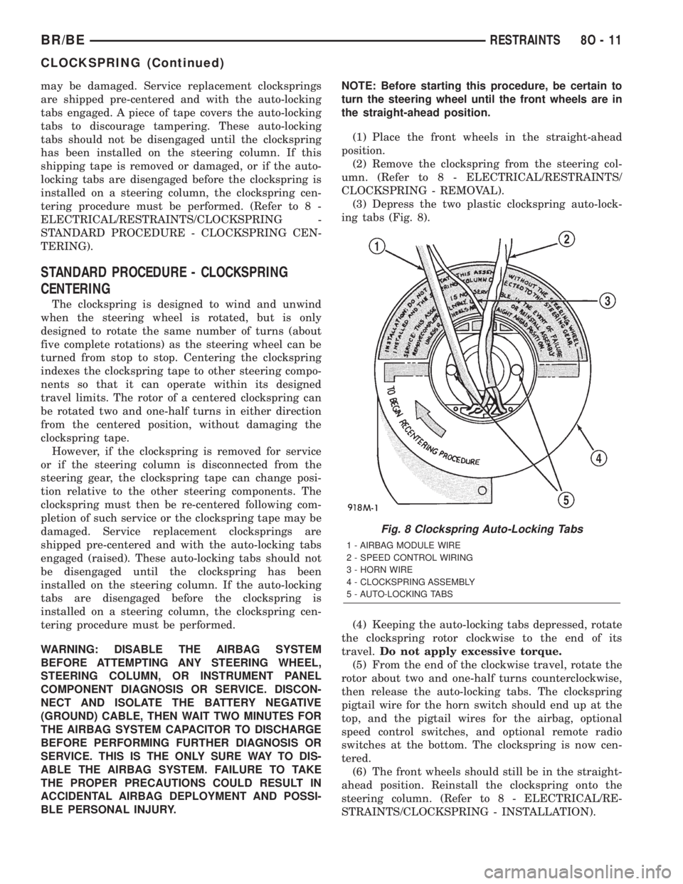
(3) Depress the two plastic clockspring auto-lock-
ing tabs (Fig. 8).
(4) Keeping the auto-locking tabs depressed, rotate
the clockspring rotor clockwise to the end of its
travel.Do not apply excessive torque.
(5) From the end of the clockwise travel, rotate the
rotor about two and one-half turns counterclockwise,
then release the auto-locking tabs. The clockspring
pigtail wire for the horn switch should end up at the
top, and the pigtail wires for the airbag, optional
speed control switches, and optional remote radio
switches at the bottom. The clockspring is now cen-
tered.
(6) The front wheels should still be in the straight-
ahead position. Reinstall the clockspring onto the
steering column. (Refer to 8 - ELECTRICAL/RE-
STRAINTS/CLOCKSPRING - INSTALLATION).
Fig. 8 Clockspring Auto-Locking Tabs
1 - AIRBAG MODULE WIRE
2 - SPEED CONTROL WIRING
3 - HORN WIRE
4 - CLOCKSPRING ASSEMBLY
5 - AUTO-LOCKING TABS
BR/BERESTRAINTS 8O - 11
CLOCKSPRING (Continued)
Page 610 of 2255
the entire driver airbag trim cover and horn switch
unit must be replaced.
WARNING: DISABLE THE AIRBAG SYSTEM
BEFORE ATTEMPTING ANY STEERING WHEEL,
STEERING COLUMN, OR INSTRUMENT PANEL
COMPONENT DIAGNOSIS OR SERVICE. DISCON-
NECT AND ISOLATE THE BATTERY NEGATIVE
(GROUND) CABLE, THEN WAIT TWO MINUTES FOR
THE AIRBAG SYSTEM CAPACITOR TO DISCHARGE
BEFORE PERFORMING FURTHER DIAGNOSIS OR
SERVICE. THIS IS THE ONLY SURE WAY TO DIS-
ABLE THE AIRBAG SYSTEM. FAILURE TO TAKE
THE PROPER PRECAUTIONS COULD RESULT IN
ACCIDENTAL AIRBAG DEPLOYMENT AND POSSI-
BLE PERSONAL INJURY.
WARNING: THE HORN SWITCH IS INTEGRAL TO
THE DRIVER AIRBAG UNIT. SERVICE OF THIS UNIT
SHOULD BE PERFORMED ONLY BY
DAIMLERCHRYSLER-TRAINED AND AUTHORIZED
DEALER SERVICE TECHNICIANS. FAILURE TO
TAKE THE PROPER PRECAUTIONS OR TO FOL-
LOW THE PROPER PROCEDURES COULD RESULT
IN ACCIDENTAL, INCOMPLETE, OR IMPROPER AIR-
BAG DEPLOYMENT AND POSSIBLE OCCUPANT
INJURIES.
WARNING: USE EXTREME CARE TO PREVENT ANY
FOREIGN MATERIAL FROM ENTERING THE DRIVER
AIRBAG, OR BECOMING ENTRAPPED BETWEEN
THE DRIVER AIRBAG CUSHION AND THE DRIVER
AIRBAG TRIM COVER. FAILURE TO OBSERVE THIS
WARNING COULD RESULT IN OCCUPANT INJURIES
UPON AIRBAG DEPLOYMENT.
WARNING: THE DRIVER AIRBAG TRIM COVER
MUST NEVER BE PAINTED. REPLACEMENT TRIM
COVERS ARE SERVICED IN THE ORIGINAL COL-
ORS. PAINT MAY CHANGE THE WAY IN WHICH THE
MATERIAL OF THE TRIM COVER RESPONDS TO AN
AIRBAG DEPLOYMENT. FAILURE TO OBSERVE
THIS WARNING COULD RESULT IN OCCUPANT
INJURIES UPON AIRBAG DEPLOYMENT.
(1) Carefully position the driver airbag in the trim
cover. Be certain that the horn switch feed and
ground pigtail wires are not pinched between the air-
bag housing and the trim cover locking blocks.
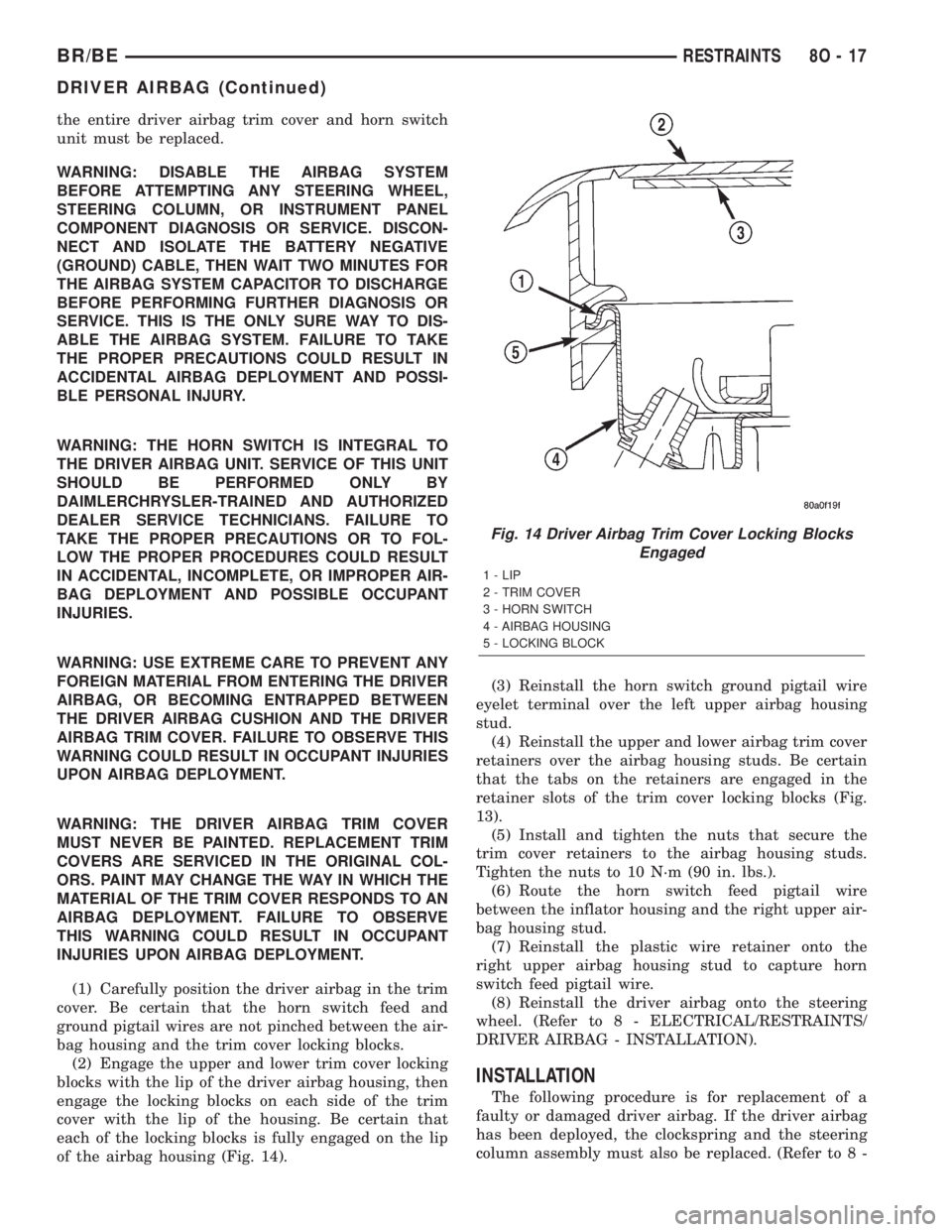
(2) Engage the upper and lower trim cover locking
blocks with the lip of the driver airbag housing, then
engage the locking blocks on each side of the trim
cover with the lip of the housing. Be certain that
each of the locking blocks is fully engaged on the lip
of the airbag housing (Fig. 14).(3) Reinstall the horn switch ground pigtail wire
eyelet terminal over the left upper airbag housing
stud.
(4) Reinstall the upper and lower airbag trim cover
retainers over the airbag housing studs. Be certain
that the tabs on the retainers are engaged in the
retainer slots of the trim cover locking blocks (Fig.
13).
(5) Install and tighten the nuts that secure the
trim cover retainers to the airbag housing studs.
Tighten the nuts to 10 N´m (90 in. lbs.).
(6) Route the horn switch feed pigtail wire
between the inflator housing and the right upper air-
bag housing stud.
(7) Reinstall the plastic wire retainer onto the
right upper airbag housing stud to capture horn
switch feed pigtail wire.
(8) Reinstall the driver airbag onto the steering
wheel. (Refer to 8 - ELECTRICAL/RESTRAINTS/
DRIVER AIRBAG - INSTALLATION).
INSTALLATION
The following procedure is for replacement of a
faulty or damaged driver airbag. If the driver airbag
has been deployed, the clockspring and the steering
column assembly must also be replaced. (Refer to 8 -
Fig. 14 Driver Airbag Trim Cover Locking Blocks
Engaged
1 - LIP
2 - TRIM COVER
3 - HORN SWITCH
4 - AIRBAG HOUSING
5 - LOCKING BLOCK
BR/BERESTRAINTS 8O - 17
DRIVER AIRBAG (Continued)
Page 611 of 2255

ELECTRICAL/RESTRAINTS/CLOCKSPRING -
REMOVAL) and (Refer to 19 - STEERING/COLUMN
- REMOVAL).
WARNING: DISABLE THE AIRBAG SYSTEM
BEFORE ATTEMPTING ANY STEERING WHEEL,
STEERING COLUMN, OR INSTRUMENT PANEL
COMPONENT DIAGNOSIS OR SERVICE. DISCON-
NECT AND ISOLATE THE BATTERY NEGATIVE
(GROUND) CABLE, THEN WAIT TWO MINUTES FOR
THE AIRBAG SYSTEM CAPACITOR TO DISCHARGE
BEFORE PERFORMING FURTHER DIAGNOSIS OR
SERVICE. THIS IS THE ONLY SURE WAY TO DIS-
ABLE THE AIRBAG SYSTEM. FAILURE TO TAKE
THE PROPER PRECAUTIONS COULD RESULT IN
ACCIDENTAL AIRBAG DEPLOYMENT AND POSSI-
BLE PERSONAL INJURY.
WARNING: USE EXTREME CARE TO PREVENT ANY
FOREIGN MATERIAL FROM ENTERING THE DRIVER
AIRBAG, OR BECOMING ENTRAPPED BETWEEN
THE DRIVER AIRBAG CUSHION AND THE DRIVER
AIRBAG TRIM COVER. FAILURE TO OBSERVE THIS
WARNING COULD RESULT IN OCCUPANT INJURIES
UPON AIRBAG DEPLOYMENT.
WARNING: THE DRIVER AIRBAG TRIM COVER
MUST NEVER BE PAINTED. REPLACEMENT TRIM
COVERS ARE SERVICED IN THE ORIGINAL COL-
ORS. PAINT MAY CHANGE THE WAY IN WHICH THE
MATERIAL OF THE TRIM COVER RESPONDS TO AN
AIRBAG DEPLOYMENT. FAILURE TO OBSERVE
THIS WARNING COULD RESULT IN OCCUPANT
INJURIES UPON AIRBAG DEPLOYMENT.
(1) Assemble the driver airbag trim cover onto the
airbag housing. (Refer to 8 - ELECTRICAL/RE-
STRAINTS/DRIVER AIRBAG - ASSEMBLY).
(2) When installing the driver airbag, reconnect
the clockspring driver airbag pigtail wire harness
connector to the airbag inflator connector receptacle
by pressing straight in on the connector (Fig. 10). You
can be certain that the connector is fully engaged by
listening carefully for a distinct, audible click as the
connector snaps into place.
(3) Reconnect the clockspring horn switch pigtail
wire harness connector to the horn switch feed pig-
tail wire connector, which is located on the back of
the driver airbag.
(4) Carefully position the driver airbag in the
steering wheel. Be certain that the clockspring pig-
tail wires in the steering wheel hub area are not
pinched between the driver airbag and the steering
wheel.(5) From the underside of the steering wheel,
install and tighten the two screws that secure the
driver airbag to the steering wheel armature.
Tighten the screws to 10.2 N´m (90 in. lbs.).
(6) Do not reconnect the battery negative cable at
this time. The airbag system verification test proce-
dure should be performed following service of any
airbag system component. (Refer to 8 - ELECTRI-
CAL/RESTRAINTS - STANDARD PROCEDURE -
VERIFICATION TEST).
FRONT SEAT BELT &
RETRACTOR
REMOVAL
REMOVAL - STANDARD CAB
WARNING: DURING AND FOLLOWING ANY SEAT
BELT SERVICE, CAREFULLY INSPECT ALL SEAT
BELTS, BUCKLES, MOUNTING HARDWARE, AND
RETRACTORS FOR PROPER INSTALLATION,
OPERATION, OR DAMAGE. REPLACE ANY BELT
THAT IS CUT, FRAYED, OR TORN. STRAIGHTEN
ANY BELT THAT IS TWISTED. TIGHTEN ANY
LOOSE FASTENERS. REPLACE ANY BELT THAT
HAS A DAMAGED OR INOPERATIVE BUCKLE OR
RETRACTOR. REPLACE ANY BELT THAT HAS A
BENT OR DAMAGED LATCH PLATE OR ANCHOR
PLATE. NEVER ATTEMPT TO REPAIR A SEAT BELT
COMPONENT. ALWAYS REPLACE DAMAGED OR
FAULTY SEAT BELT COMPONENTS WITH THE COR-
RECT, NEW AND UNUSED REPLACEMENT PARTS
LISTED IN THE MOPAR PARTS CATALOG.
(1) Move the front seats to their most forward
position for easiest access to the front shoulder belt
lower seat belt anchor plate, the retractor, and the
B-pillar.
(2) Remove the screw that secures the lower seat
belt anchor plate to the floor panel near the base of
the B-pillar.
(3) Unsnap and lift the front shoulder belt turning
loop cover to access the screw that secures the turn-
ing loop to the height adjuster (Fig. 15).
(4) Remove the screw that secures the shoulder
belt turning loop to the height adjuster.
(5) Remove the shoulder belt turning loop from the
height adjuster.
(6) Remove the trim from the B-pillar. (Refer to 23
- BODY/INTERIOR/B-PILLAR TRIM - REMOVAL).
(7) Disengage the front seat shoulder belt turning
loop and lower seat belt anchor plate from the B-pil-
lar trim.
8O - 18 RESTRAINTSBR/BE
DRIVER AIRBAG (Continued)
Page 616 of 2255
INSTALLATION
WARNING: DISABLE THE AIRBAG SYSTEM
BEFORE ATTEMPTING ANY STEERING WHEEL,
STEERING COLUMN, OR INSTRUMENT PANEL
COMPONENT DIAGNOSIS OR SERVICE. DISCON-
NECT AND ISOLATE THE BATTERY NEGATIVE
(GROUND) CABLE, THEN WAIT TWO MINUTES FOR
THE AIRBAG SYSTEM CAPACITOR TO DISCHARGE
BEFORE PERFORMING FURTHER DIAGNOSIS OR
SERVICE. THIS IS THE ONLY SURE WAY TO DIS-
ABLE THE AIRBAG SYSTEM. FAILURE TO TAKE
THE PROPER PRECAUTIONS COULD RESULT IN
ACCIDENTAL AIRBAG DEPLOYMENT AND POSSI-
BLE PERSONAL INJURY.
WARNING: WHEN REMOVING A DEPLOYED AIR-
BAG, RUBBER GLOVES, EYE PROTECTION, AND A
LONG-SLEEVED SHIRT SHOULD BE WORN. THERE
MAY BE DEPOSITS ON THE AIRBAG UNIT AND
OTHER INTERIOR SURFACES. IN LARGE DOSES,
THESE DEPOSITS MAY CAUSE IRRITATION TO THE
SKIN AND EYES.
WARNING: USE EXTREME CARE TO PREVENT ANY
FOREIGN MATERIAL FROM ENTERING THE PAS-
SENGER AIRBAG, OR BECOMING ENTRAPPED
BETWEEN THE PASSENGER AIRBAG CUSHION
AND THE PASSENGER AIRBAG DOOR. FAILURE TO
OBSERVE THIS WARNING COULD RESULT IN
OCCUPANT INJURIES UPON AIRBAG DEPLOY-
MENT.
WARNING: THE PASSENGER AIRBAG DOOR MUST
NEVER BE PAINTED. REPLACEMENT PASSENGER
AIRBAG DOORS ARE SERVICED IN THE ORIGINAL
COLORS. PAINT MAY CHANGE THE WAY IN WHICH
THE MATERIAL OF THE AIRBAG DOOR RESPONDS
TO AN AIRBAG DEPLOYMENT. FAILURE TO
OBSERVE THIS WARNING COULD RESULT IN
OCCUPANT INJURIES UPON AIRBAG DEPLOY-
MENT.
(1) Carefully inspect the five receptacle slots
around the top and sides of the passenger airbag
door opening of the instrument panel top cover.
Remove any of the small metal airbag door snap
retainers that did not remain on the molded airbag
door tabs during the removal procedure.
(2) If the removed passenger airbag module is
being reinstalled, install the metal snap retainers
recovered in Step 1onto the proper airbag door tabs.
Each of the five molded airbag door tabs must have a
snap retainer on it before it is installed in the instru-ment panel. New replacement passenger airbags
come with new airbag door snap retainers installed.
(3) Carefully position the passenger airbag onto
the instrument panel.
(4) Align the five tabs and retainers on the upper
edge and sides of the passenger airbag door with the
receptacles in the instrument panel top cover.
(5) Using hand pressure, press firmly on the pas-
senger airbag door over each of the tab and retainer
locations until each of them is fully engaged in its
receptacle. Be certain that each of the metal snap
retainers is in position on the airbag door tabs.
(6) Install and tighten the five screws that secure
the passenger airbag front and rear mounting brack-
ets to the instrument panel (Fig. 18). Tighten the
screws to 9 N´m (80 in. lbs.).
(7) Install and tighten the four screws that secure
the two plastic support brackets of the passenger air-
bag door panel outlet housing to the glove box open-
ing upper reinforcement. Tighten the screws to 2.2
N´m (20 in. lbs.).
(8) Reach through and above the glove box opening
to access and reconnect the passenger airbag pigtail
wire connector to the instrument panel wire harness
connector (Fig. 17). Be certain that the passenger air-
bag pigtail wire connector is fully engaged with and
latched to the instrument panel wire harness connec-
tor.
(9) Reinstall the glove box opening upper trim onto
the instrument panel. (Refer to 23 - BODY/INSTRU-
MENT PANEL/GLOVE BOX OPENING UPPER
TRIM - INSTALLATION).
(10) Reinstall the glove box onto the instrument
panel. (Refer to 23 - BODY/INSTRUMENT PANEL/
GLOVE BOX - INSTALLATION).
(11) Do not reconnect the battery negative cable at
this time. The airbag system verification test proce-
dure should be performed following service of any
airbag system component. (Refer to 8 - ELECTRI-
CAL/RESTRAINTS - STANDARD PROCEDURE -
VERIFICATION TEST).
PASSENGER AIRBAG ON/OFF
SWITCH
DESCRIPTION
The passenger airbag on-off switch is standard
equipment on this model when it is not equipped
with a full size rear seat. This switch is a single pole,
single throw switch with a single integral red Light-
Emitting Diode (LED), and a non-coded key cylinder-
type actuator. The switch is located in the upper
right corner of instrument panel cluster bezel, near
the center of instrument panel to make the Off indi-
cator visible to all front seat occupants. When the
BR/BERESTRAINTS 8O - 23
PASSENGER AIRBAG (Continued)