2002 DODGE RAM tire pressure
[x] Cancel search: tire pressurePage 1385 of 2255
(7) Because fuel pump relay was removed, a Diag-
nostic Trouble Code (DTC) may have been set. After
testing is completed, and relay has been installed,
use DRB scan tool to remove DTC.
Fuel Supply Restriction Test:
Due to very small vacuum specifications, the DRB
scan tool along with the Periphal Expansion Port
(PEP) Module and 0±15 psi transducer must be used.
(8) Verify transfer pump pressure is OK before
performing restriction test.
(9) Locate and disconnect fuel supply line quick-
connect fitting at left-rear of engine (Fig. 63). After
disconnecting line, plastic clip will remain attached
to metal fuel line at engine. Carefully remove clip
from metal line. Snap same clip into fuel supply
hose.
(10) Install Special Rubber Adapter Hose Tool
6631 (3/8º) into ends of disconnected fuel supply line.
(11) Install transducer from PEP module to brass
ªTº fitting on tool 6631.
(12) Hook up DRB scan tool to transducer.
WARNING: DO NOT STAND IN LINE WITH THE
COOLING FAN FOR THE FOLLOWING STEPS.
(13) Start engine and record vacuum reading with
engine speed at high-idle (high-idle means engine
speed is at 100 percent throttle and no load). The
fuel restriction testMUSTbe done with engine speed
at high-idle.
(14) If vacuum reading islessthan 6 in/hg. (0±152
mm hg.), test is OK. If vacuum reading ishigher
than 6 in/hg. (152 mm hg.), restriction exists in fuel
supply line or in fuel tank module. Check fuel supply
line for damage, dents or kinking. If OK, remove
module and check module and lines for blockage.
Also check fuel pump inlet filter at bottom of module
for obstructions.
Testing For Air Leaks in Fuel Supply Side:
(15) A 3±foot section of 3/8º I.D. clear tubing is
required for this test.
(16) Using a tire core valve removal tool, carefully
remove core valve from inlet fitting test port.
(17) Attach and clamp the 3/8ºclear hose to fitting
nipple.
(18) Place other end of hose into a large clear con-
tainer. Allow hose to loop as high as possibleabove
test port.
(19) The fuel transfer pump can be put into a 25
second run (test) mode if key is quickly turned to
crank position and released back to run position
without starting engine.
To prevent engine from starting in this test, first
remove fuel system relay (fuel injection pump relay).
Relay is located in Power Distribution Center (PDC).
Refer to label under PDC cover for relay location.
Because fuel pump relay was removed, a DiagnosticTrouble Code (DTC) may have been set. After testing
is completed, and relay has been installed, use DRB
scan tool to remove DTC.
(20) Allow air to purge from empty hose before
examining for air bubbles. Air bubbles should not be
present.
(21) If bubbles are present, check for leaks in sup-
ply line to fuel tank.
(22) If supply line is not leaking, remove fuel tank
module and remove filter at bottom of module (filter
snaps to module). Check for leaks between supply
nipple at top of module, and filter opening at bottom
of module. Replace module if necessary.
(23) After performing test, install core back into
test fitting. Before installing protective cap, be sure
fitting is not leaking.
REMOVAL
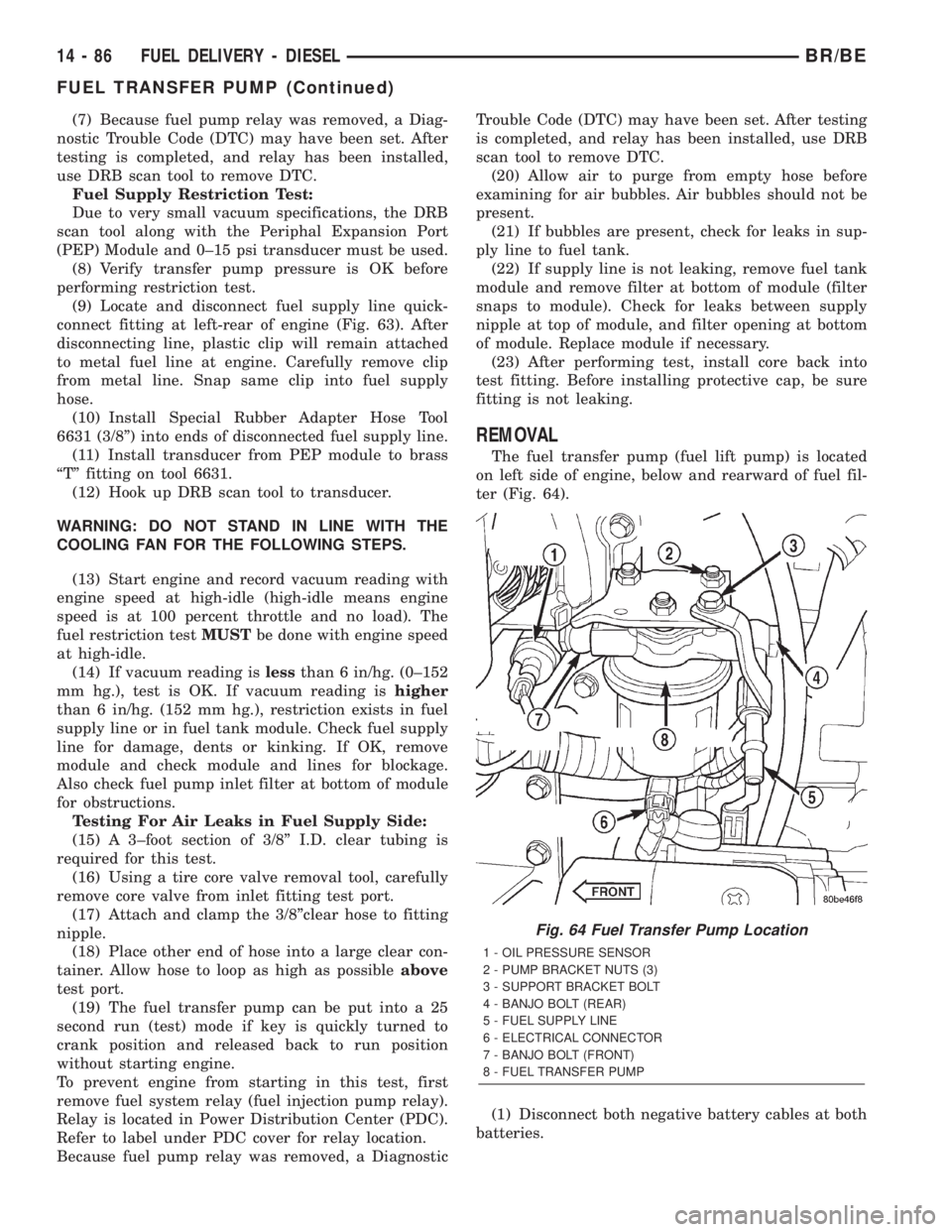
The fuel transfer pump (fuel lift pump) is located
on left side of engine, below and rearward of fuel fil-
ter (Fig. 64).
(1) Disconnect both negative battery cables at both
batteries.
Fig. 64 Fuel Transfer Pump Location
1 - OIL PRESSURE SENSOR
2 - PUMP BRACKET NUTS (3)
3 - SUPPORT BRACKET BOLT
4 - BANJO BOLT (REAR)
5 - FUEL SUPPLY LINE
6 - ELECTRICAL CONNECTOR
7 - BANJO BOLT (FRONT)
8 - FUEL TRANSFER PUMP
14 - 86 FUEL DELIVERY - DIESELBR/BE
FUEL TRANSFER PUMP (Continued)
Page 1411 of 2255
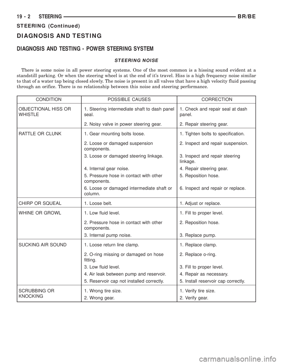
DIAGNOSIS AND TESTING
DIAGNOSIS AND TESTING - POWER STEERING SYSTEM
STEERING NOISE
There is some noise in all power steering systems. One of the most common is a hissing sound evident at a
standstill parking. Or when the steering wheel is at the end of it's travel. Hiss is a high frequency noise similar
to that of a water tap being closed slowly. The noise is present in all valves that have a high velocity fluid passing
through an orifice. There is no relationship between this noise and steering performance.
CONDITION POSSIBLE CAUSES CORRECTION
OBJECTIONAL HISS OR
WHISTLE1. Steering intermediate shaft to dash panel
seal.1. Check and repair seal at dash
panel.
2. Noisy valve in power steering gear. 2. Repair steering gear.
RATTLE OR CLUNK 1. Gear mounting bolts loose. 1. Tighten bolts to specification.
2. Loose or damaged suspension
components.2. Inspect and repair suspension.
3. Loose or damaged steering linkage. 3. Inspect and repair steering
linkage.
4. Internal gear noise. 4. Repair steering gear.
5. Pressure hose in contact with other
components.5. Reposition hose.
6. Loose or damaged intermediate shaft or
column.6. Inspect and repair or replace.
CHIRP OR SQUEAL 1. Loose belt. 1. Adjust or replace.
WHINE OR GROWL 1. Low fluid level. 1. Fill to proper level.
2. Pressure hose in contact with other
components.2. Reposition hose.
3. Internal pump noise. 3. Replace pump.
SUCKING AIR SOUND 1. Loose return line clamp. 1. Replace clamp.
2. O-ring missing or damaged on hose
fitting.2. Replace o-ring.
3. Low fluid level. 3. Fill to proper level.
4. Air leak between pump and reservoir. 4. Repair as necessary.
5. Reservoir cap not installed correctly. 5. Install reservoir cap correctly.
SCRUBBING OR
KNOCKING1. Wrong tire size. 1. Verify tire size.
2. Wrong gear. 2. Verify gear.
19 - 2 STEERINGBR/BE
STEERING (Continued)
Page 1412 of 2255
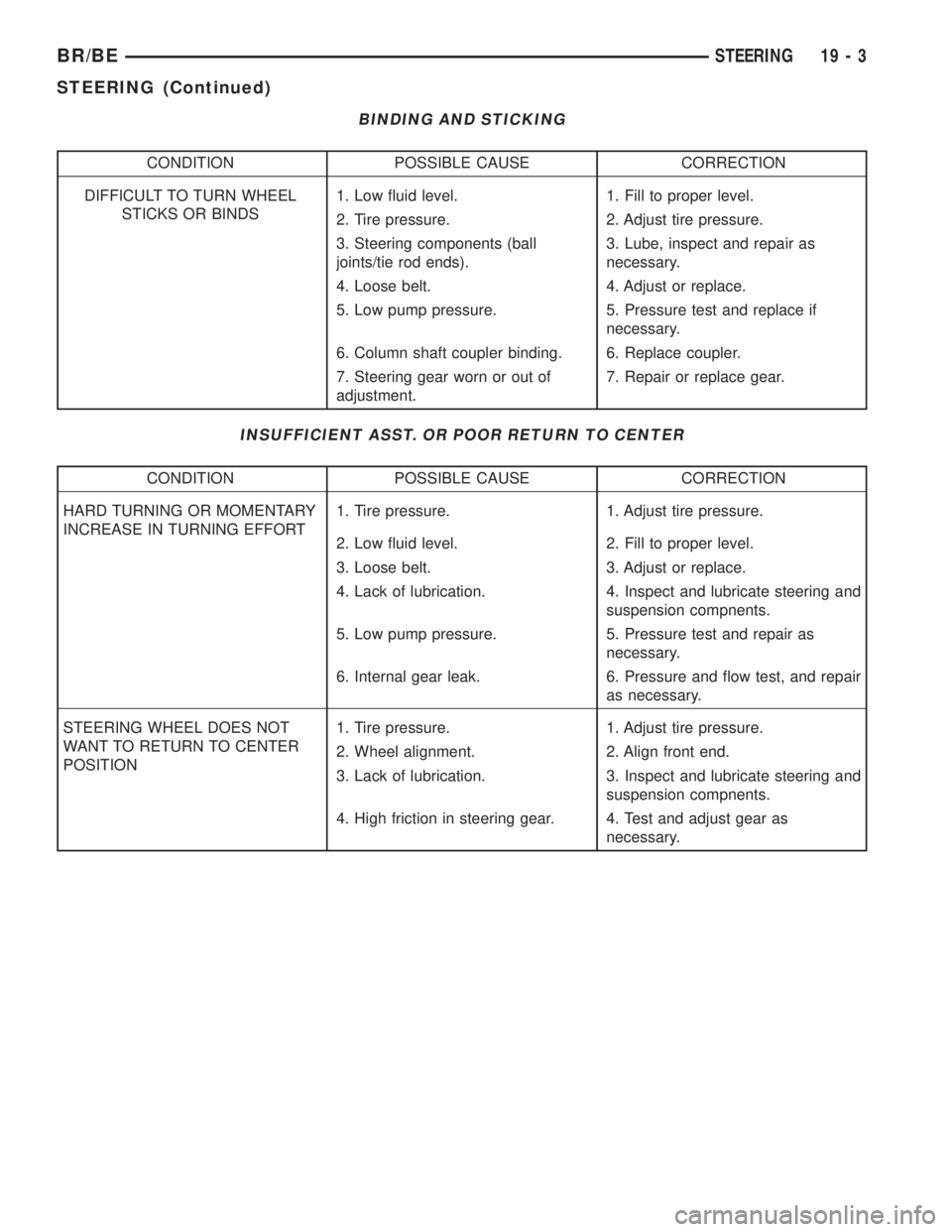
BINDING AND STICKING
CONDITION POSSIBLE CAUSE CORRECTION
DIFFICULT TO TURN WHEEL
STICKS OR BINDS1. Low fluid level. 1. Fill to proper level.
2. Tire pressure. 2. Adjust tire pressure.
3. Steering components (ball
joints/tie rod ends).3. Lube, inspect and repair as
necessary.
4. Loose belt. 4. Adjust or replace.
5. Low pump pressure. 5. Pressure test and replace if
necessary.
6. Column shaft coupler binding. 6. Replace coupler.
7. Steering gear worn or out of
adjustment.7. Repair or replace gear.
INSUFFICIENT ASST. OR POOR RETURN TO CENTER
CONDITION POSSIBLE CAUSE CORRECTION
HARD TURNING OR MOMENTARY
INCREASE IN TURNING EFFORT1. Tire pressure. 1. Adjust tire pressure.
2. Low fluid level. 2. Fill to proper level.
3. Loose belt. 3. Adjust or replace.
4. Lack of lubrication. 4. Inspect and lubricate steering and
suspension compnents.
5. Low pump pressure. 5. Pressure test and repair as
necessary.
6. Internal gear leak. 6. Pressure and flow test, and repair
as necessary.
STEERING WHEEL DOES NOT
WANT TO RETURN TO CENTER
POSITION1. Tire pressure. 1. Adjust tire pressure.
2. Wheel alignment. 2. Align front end.
3. Lack of lubrication. 3. Inspect and lubricate steering and
suspension compnents.
4. High friction in steering gear. 4. Test and adjust gear as
necessary.
BR/BESTEERING 19 - 3
STEERING (Continued)
Page 1413 of 2255
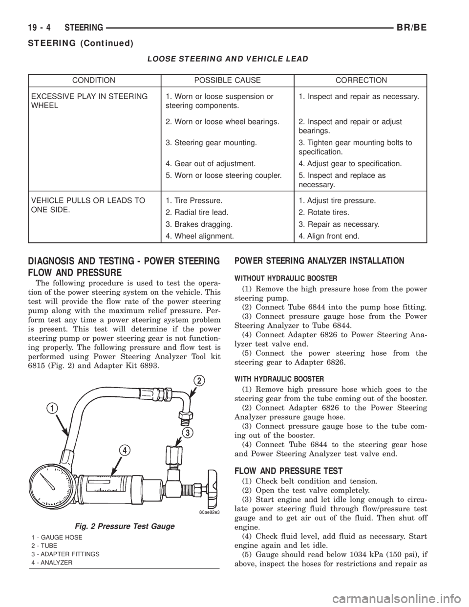
LOOSE STEERING AND VEHICLE LEAD
CONDITION POSSIBLE CAUSE CORRECTION
EXCESSIVE PLAY IN STEERING
WHEEL1. Worn or loose suspension or
steering components.1. Inspect and repair as necessary.
2. Worn or loose wheel bearings. 2. Inspect and repair or adjust
bearings.
3. Steering gear mounting. 3. Tighten gear mounting bolts to
specification.
4. Gear out of adjustment. 4. Adjust gear to specification.
5. Worn or loose steering coupler. 5. Inspect and replace as
necessary.
VEHICLE PULLS OR LEADS TO
ONE SIDE.1. Tire Pressure. 1. Adjust tire pressure.
2. Radial tire lead. 2. Rotate tires.
3. Brakes dragging. 3. Repair as necessary.
4. Wheel alignment. 4. Align front end.
DIAGNOSIS AND TESTING - POWER STEERING
FLOW AND PRESSURE
The following procedure is used to test the opera-
tion of the power steering system on the vehicle. This
test will provide the flow rate of the power steering
pump along with the maximum relief pressure. Per-
form test any time a power steering system problem
is present. This test will determine if the power
steering pump or power steering gear is not function-
ing properly. The following pressure and flow test is
performed using Power Steering Analyzer Tool kit
6815 (Fig. 2) and Adapter Kit 6893.
POWER STEERING ANALYZER INSTALLATION
WITHOUT HYDRAULIC BOOSTER
(1) Remove the high pressure hose from the power
steering pump.
(2) Connect Tube 6844 into the pump hose fitting.
(3) Connect pressure gauge hose from the Power
Steering Analyzer to Tube 6844.
(4) Connect Adapter 6826 to Power Steering Ana-
lyzer test valve end.
(5) Connect the power steering hose from the
steering gear to Adapter 6826.
WITH HYDRAULIC BOOSTER
(1) Remove high pressure hose which goes to the
steering gear from the tube coming out of the booster.
(2) Connect Adapter 6826 to the Power Steering
Analyzer pressure gauge hose.
(3) Connect pressure gauge hose to the tube com-
ing out of the booster.
(4) Connect Tube 6844 to the steering gear hose
and Power Steering Analyzer test valve end.
FLOW AND PRESSURE TEST
(1) Check belt condition and tension.
(2) Open the test valve completely.
(3) Start engine and let idle long enough to circu-
late power steering fluid through flow/pressure test
gauge and to get air out of the fluid. Then shut off
engine.
(4) Check fluid level, add fluid as necessary. Start
engine again and let idle.
(5) Gauge should read below 1034 kPa (150 psi), if
above, inspect the hoses for restrictions and repair as
Fig. 2 Pressure Test Gauge
1 - GAUGE HOSE
2 - TUBE
3 - ADAPTER FITTINGS
4 - ANALYZER
19 - 4 STEERINGBR/BE
STEERING (Continued)
Page 1545 of 2255
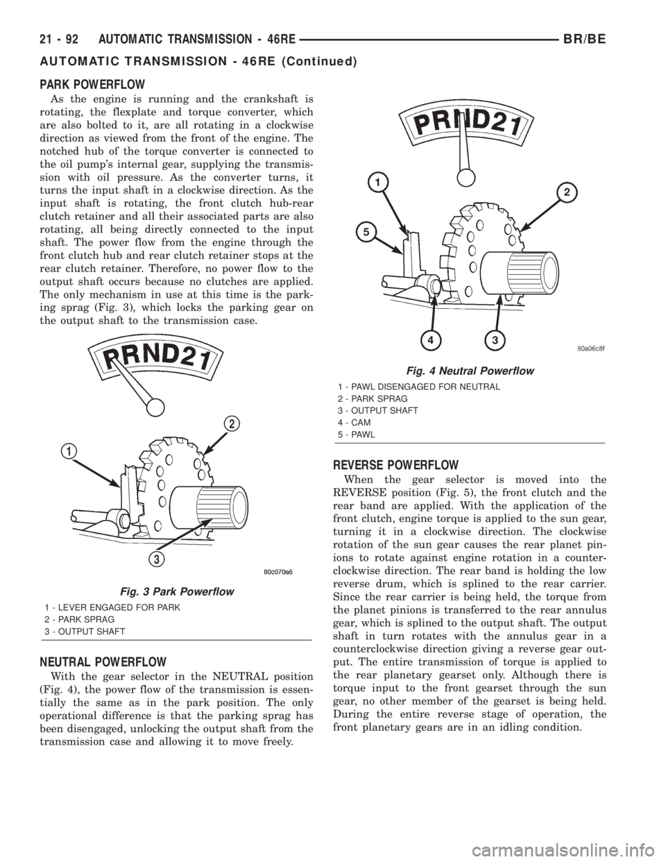
PARK POWERFLOW
As the engine is running and the crankshaft is
rotating, the flexplate and torque converter, which
are also bolted to it, are all rotating in a clockwise
direction as viewed from the front of the engine. The
notched hub of the torque converter is connected to
the oil pump's internal gear, supplying the transmis-
sion with oil pressure. As the converter turns, it
turns the input shaft in a clockwise direction. As the
input shaft is rotating, the front clutch hub-rear
clutch retainer and all their associated parts are also
rotating, all being directly connected to the input
shaft. The power flow from the engine through the
front clutch hub and rear clutch retainer stops at the
rear clutch retainer. Therefore, no power flow to the
output shaft occurs because no clutches are applied.
The only mechanism in use at this time is the park-
ing sprag (Fig. 3), which locks the parking gear on
the output shaft to the transmission case.
NEUTRAL POWERFLOW
With the gear selector in the NEUTRAL position
(Fig. 4), the power flow of the transmission is essen-
tially the same as in the park position. The only
operational difference is that the parking sprag has
been disengaged, unlocking the output shaft from the
transmission case and allowing it to move freely.
REVERSE POWERFLOW
When the gear selector is moved into the
REVERSE position (Fig. 5), the front clutch and the
rear band are applied. With the application of the
front clutch, engine torque is applied to the sun gear,
turning it in a clockwise direction. The clockwise
rotation of the sun gear causes the rear planet pin-
ions to rotate against engine rotation in a counter-
clockwise direction. The rear band is holding the low
reverse drum, which is splined to the rear carrier.
Since the rear carrier is being held, the torque from
the planet pinions is transferred to the rear annulus
gear, which is splined to the output shaft. The output
shaft in turn rotates with the annulus gear in a
counterclockwise direction giving a reverse gear out-
put. The entire transmission of torque is applied to
the rear planetary gearset only. Although there is
torque input to the front gearset through the sun
gear, no other member of the gearset is being held.
During the entire reverse stage of operation, the
front planetary gears are in an idling condition.
Fig. 3 Park Powerflow
1 - LEVER ENGAGED FOR PARK
2 - PARK SPRAG
3 - OUTPUT SHAFT
Fig. 4 Neutral Powerflow
1 - PAWL DISENGAGED FOR NEUTRAL
2 - PARK SPRAG
3 - OUTPUT SHAFT
4 - CAM
5-PAWL
21 - 92 AUTOMATIC TRANSMISSION - 46REBR/BE
AUTOMATIC TRANSMISSION - 46RE (Continued)
Page 1659 of 2255
(9) Install piston spring in retainer and on top of
piston. Concave side of spring faces downward
(toward piston).
(10) Install the spacer ring and wave spring into
the retainer. Be sure spring is completely seated in
retainer groove.
(11) Install pressure plate (Fig. 223). Ridged side
of plate faces downward (toward piston) and flat side
toward clutch pack.
(12) Install first clutch disc in retainer on top of
pressure plate. Then install a clutch plate followed
by a clutch disc until entire clutch pack is installed
(4 discs and 3 plates are required) (Fig. 223).
(13) Install the reaction plate.
(14) Install selective snap-ring. Be sure snap-ring
is fully seated in retainer groove.
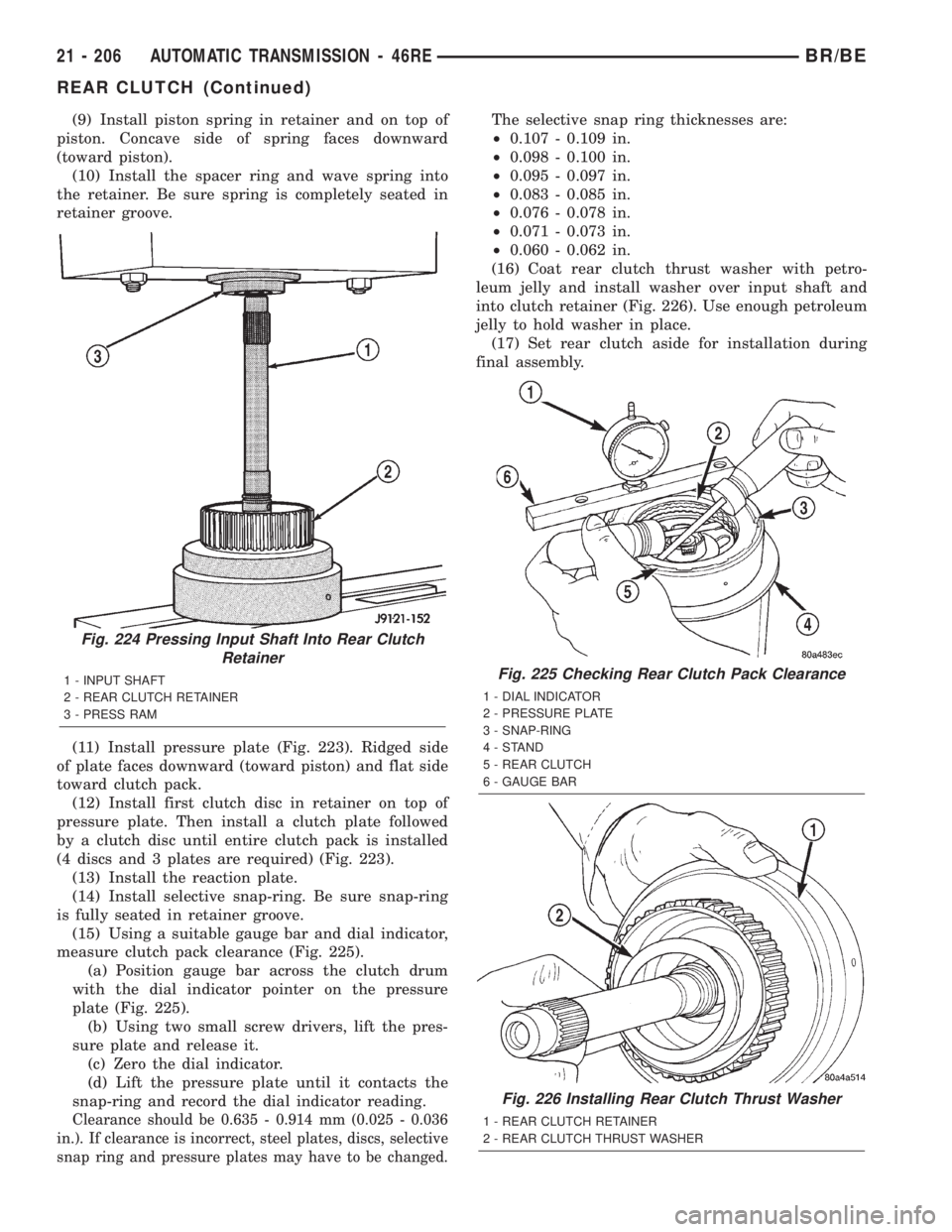
(15) Using a suitable gauge bar and dial indicator,
measure clutch pack clearance (Fig. 225).
(a) Position gauge bar across the clutch drum
with the dial indicator pointer on the pressure
plate (Fig. 225).
(b) Using two small screw drivers, lift the pres-
sure plate and release it.
(c) Zero the dial indicator.
(d) Lift the pressure plate until it contacts the
snap-ring and record the dial indicator reading.
Clearance should be 0.635 - 0.914 mm (0.025 - 0.036
in.). If clearance is incorrect, steel plates, discs, selective
snap ring and pressure plates may have to be changed.
The selective snap ring thicknesses are:
²0.107 - 0.109 in.
²0.098 - 0.100 in.
²0.095 - 0.097 in.
²0.083 - 0.085 in.
²0.076 - 0.078 in.
²0.071 - 0.073 in.
²0.060 - 0.062 in.
(16) Coat rear clutch thrust washer with petro-
leum jelly and install washer over input shaft and
into clutch retainer (Fig. 226). Use enough petroleum
jelly to hold washer in place.
(17) Set rear clutch aside for installation during
final assembly.
Fig. 224 Pressing Input Shaft Into Rear Clutch
Retainer
1 - INPUT SHAFT
2 - REAR CLUTCH RETAINER
3 - PRESS RAMFig. 225 Checking Rear Clutch Pack Clearance
1 - DIAL INDICATOR
2 - PRESSURE PLATE
3 - SNAP-RING
4-STAND
5 - REAR CLUTCH
6 - GAUGE BAR
Fig. 226 Installing Rear Clutch Thrust Washer
1 - REAR CLUTCH RETAINER
2 - REAR CLUTCH THRUST WASHER
21 - 206 AUTOMATIC TRANSMISSION - 46REBR/BE
REAR CLUTCH (Continued)
Page 1717 of 2255
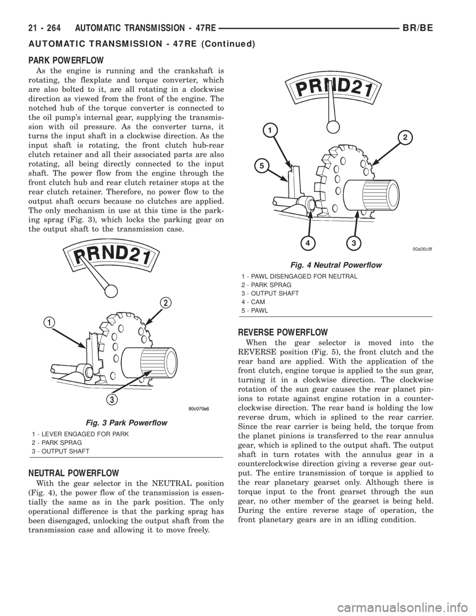
PARK POWERFLOW
As the engine is running and the crankshaft is
rotating, the flexplate and torque converter, which
are also bolted to it, are all rotating in a clockwise
direction as viewed from the front of the engine. The
notched hub of the torque converter is connected to
the oil pump's internal gear, supplying the transmis-
sion with oil pressure. As the converter turns, it
turns the input shaft in a clockwise direction. As the
input shaft is rotating, the front clutch hub-rear
clutch retainer and all their associated parts are also
rotating, all being directly connected to the input
shaft. The power flow from the engine through the
front clutch hub and rear clutch retainer stops at the
rear clutch retainer. Therefore, no power flow to the
output shaft occurs because no clutches are applied.
The only mechanism in use at this time is the park-
ing sprag (Fig. 3), which locks the parking gear on
the output shaft to the transmission case.
NEUTRAL POWERFLOW
With the gear selector in the NEUTRAL position
(Fig. 4), the power flow of the transmission is essen-
tially the same as in the park position. The only
operational difference is that the parking sprag has
been disengaged, unlocking the output shaft from the
transmission case and allowing it to move freely.
REVERSE POWERFLOW
When the gear selector is moved into the
REVERSE position (Fig. 5), the front clutch and the
rear band are applied. With the application of the
front clutch, engine torque is applied to the sun gear,
turning it in a clockwise direction. The clockwise
rotation of the sun gear causes the rear planet pin-
ions to rotate against engine rotation in a counter-
clockwise direction. The rear band is holding the low
reverse drum, which is splined to the rear carrier.
Since the rear carrier is being held, the torque from
the planet pinions is transferred to the rear annulus
gear, which is splined to the output shaft. The output
shaft in turn rotates with the annulus gear in a
counterclockwise direction giving a reverse gear out-
put. The entire transmission of torque is applied to
the rear planetary gearset only. Although there is
torque input to the front gearset through the sun
gear, no other member of the gearset is being held.
During the entire reverse stage of operation, the
front planetary gears are in an idling condition.
Fig. 3 Park Powerflow
1 - LEVER ENGAGED FOR PARK
2 - PARK SPRAG
3 - OUTPUT SHAFT
Fig. 4 Neutral Powerflow
1 - PAWL DISENGAGED FOR NEUTRAL
2 - PARK SPRAG
3 - OUTPUT SHAFT
4 - CAM
5-PAWL
21 - 264 AUTOMATIC TRANSMISSION - 47REBR/BE
AUTOMATIC TRANSMISSION - 47RE (Continued)
Page 1831 of 2255
(11) Install pressure plate (Fig. 223). Ridged side
of plate faces downward (toward piston) and flat side
toward clutch pack.
(12) Install first clutch disc in retainer on top of
pressure plate. Then install a clutch plate followed
by a clutch disc until entire clutch pack is installed
(4 discs and 3 plates are required) (Fig. 223).
(13) Install the reaction plate.
(14) Install selective snap-ring. Be sure snap-ring
is fully seated in retainer groove.
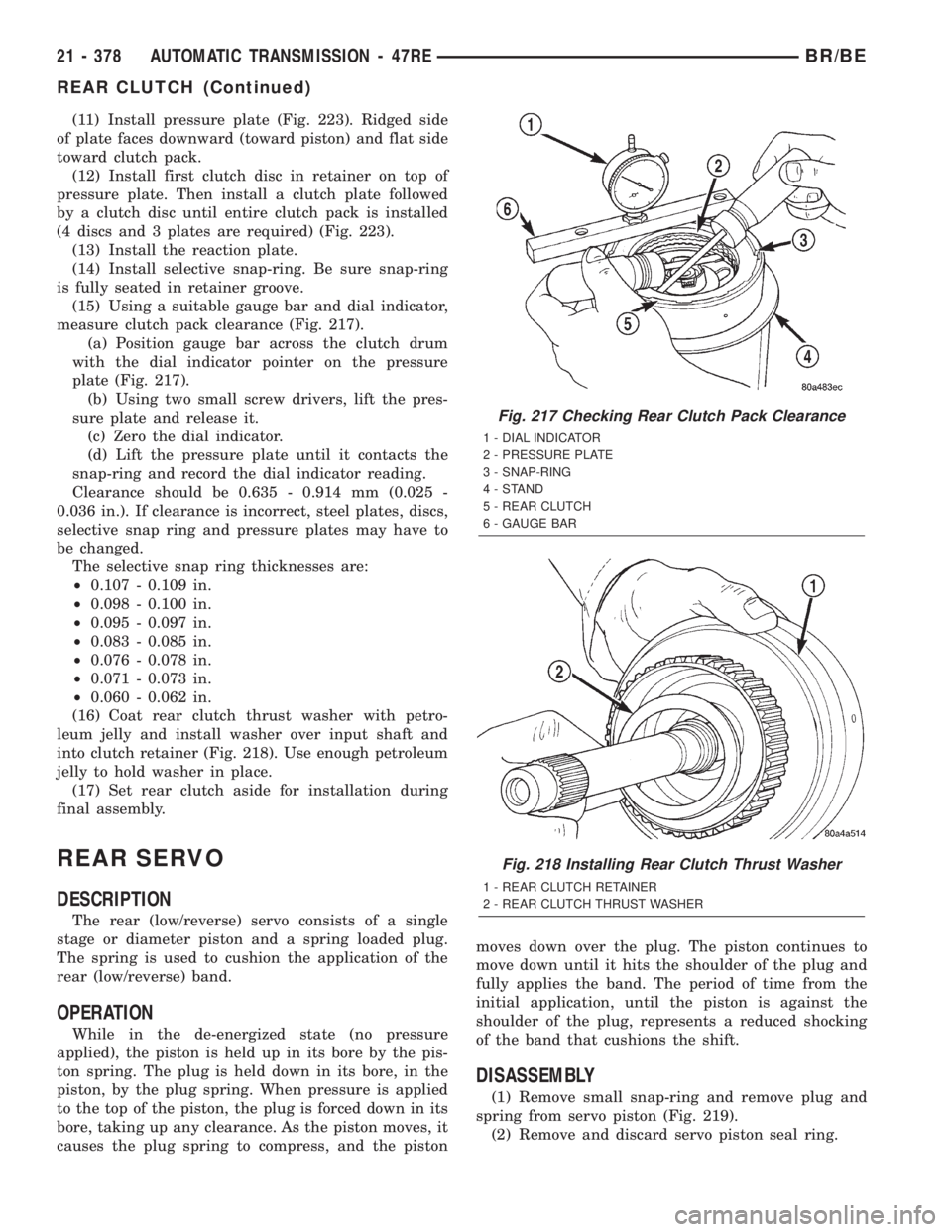
(15) Using a suitable gauge bar and dial indicator,
measure clutch pack clearance (Fig. 217).
(a) Position gauge bar across the clutch drum
with the dial indicator pointer on the pressure
plate (Fig. 217).
(b) Using two small screw drivers, lift the pres-
sure plate and release it.
(c) Zero the dial indicator.
(d) Lift the pressure plate until it contacts the
snap-ring and record the dial indicator reading.
Clearance should be 0.635 - 0.914 mm (0.025 -
0.036 in.). If clearance is incorrect, steel plates, discs,
selective snap ring and pressure plates may have to
be changed.
The selective snap ring thicknesses are:
²0.107 - 0.109 in.
²0.098 - 0.100 in.
²0.095 - 0.097 in.
²0.083 - 0.085 in.
²0.076 - 0.078 in.
²0.071 - 0.073 in.
²0.060 - 0.062 in.
(16) Coat rear clutch thrust washer with petro-
leum jelly and install washer over input shaft and
into clutch retainer (Fig. 218). Use enough petroleum
jelly to hold washer in place.
(17) Set rear clutch aside for installation during
final assembly.
REAR SERVO
DESCRIPTION
The rear (low/reverse) servo consists of a single
stage or diameter piston and a spring loaded plug.
The spring is used to cushion the application of the
rear (low/reverse) band.
OPERATION
While in the de-energized state (no pressure
applied), the piston is held up in its bore by the pis-
ton spring. The plug is held down in its bore, in the
piston, by the plug spring. When pressure is applied
to the top of the piston, the plug is forced down in its
bore, taking up any clearance. As the piston moves, it
causes the plug spring to compress, and the pistonmoves down over the plug. The piston continues to
move down until it hits the shoulder of the plug and
fully applies the band. The period of time from the
initial application, until the piston is against the
shoulder of the plug, represents a reduced shocking
of the band that cushions the shift.
DISASSEMBLY
(1) Remove small snap-ring and remove plug and
spring from servo piston (Fig. 219).
(2) Remove and discard servo piston seal ring.
Fig. 217 Checking Rear Clutch Pack Clearance
1 - DIAL INDICATOR
2 - PRESSURE PLATE
3 - SNAP-RING
4-STAND
5 - REAR CLUTCH
6 - GAUGE BAR
Fig. 218 Installing Rear Clutch Thrust Washer
1 - REAR CLUTCH RETAINER
2 - REAR CLUTCH THRUST WASHER
21 - 378 AUTOMATIC TRANSMISSION - 47REBR/BE
REAR CLUTCH (Continued)