2002 DODGE RAM fuel pump
[x] Cancel search: fuel pumpPage 462 of 2255
²Terminal number 30 is connected to battery volt-
age. For both the ASD and fuel pump relays, termi-
nal 30 is connected to battery voltage at all times.
²The PCM grounds the coil side of the relay
through terminal number 85.
²Terminal number 86 supplies voltage to the coil
side of the relay.
²When the PCM de-energizes the ASD and fuel
pump relays, terminal number 87A connects to termi-
nal 30. This is the Off position. In the off position,
voltage is not supplied to the rest of the circuit. Ter-
minal 87A is the center terminal on the relay.
²When the PCM energizes the ASD and fuel
pump relays, terminal 87 connects to terminal 30.
This is the On position. Terminal 87 supplies voltage
to the rest of the circuit.
The following procedure applies to the ASD and
fuel pump relays.
(1) Remove relay from connector before testing.
(2) With the relay removed from the vehicle, use
an ohmmeter to check the resistance between termi-
nals 85 and 86. The resistance should be 75 ohms +/-
5 ohms.
(3) Connect the ohmmeter between terminals 30
and 87A. The ohmmeter should show continuity
between terminals 30 and 87A.
(4) Connect the ohmmeter between terminals 87
and 30. The ohmmeter should not show continuity at
this time.
(5) Connect one end of a jumper wire (16 gauge or
smaller) to relay terminal 85. Connect the other end
of the jumper wire to the ground side of a 12 volt
power source.
(6) Connect one end of another jumper wire (16
gauge or smaller) to the power side of the 12 volt
power source.Do not attach the other end of the
jumper wire to the relay at this time.
WARNING: DO NOT ALLOW OHMMETER TO CON-
TACT TERMINALS 85 OR 86 DURING THIS TEST.
DAMAGE TO OHMMETER MAY RESULT.
(7) Attach the other end of the jumper wire to
relay terminal 86. This activates the relay. The ohm-
meter should now show continuity between relay ter-
minals 87 and 30. The ohmmeter should not show
continuity between relay terminals 87A and 30.
(8) Disconnect jumper wires.(9) Replace the relay if it did not pass the continu-
ity and resistance tests. If the relay passed the tests,
it operates properly. Check the remainder of the ASD
and fuel pump relay circuits. Refer to 8, Wiring Dia-
grams.
REMOVAL
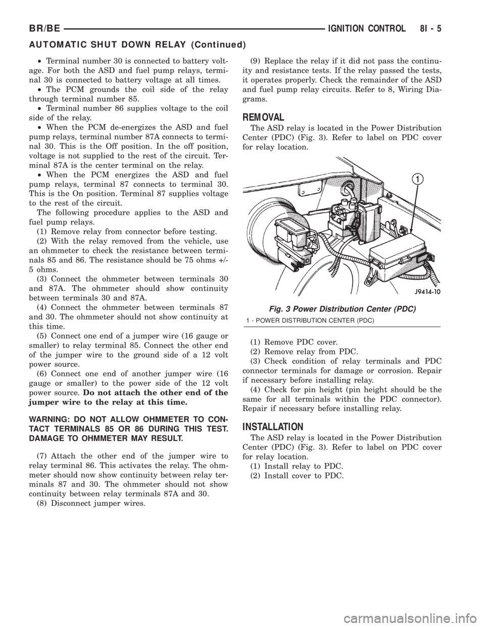
The ASD relay is located in the Power Distribution
Center (PDC) (Fig. 3). Refer to label on PDC cover
for relay location.
(1) Remove PDC cover.
(2) Remove relay from PDC.
(3) Check condition of relay terminals and PDC
connector terminals for damage or corrosion. Repair
if necessary before installing relay.
(4) Check for pin height (pin height should be the
same for all terminals within the PDC connector).
Repair if necessary before installing relay.
INSTALLATION
The ASD relay is located in the Power Distribution
Center (PDC) (Fig. 3). Refer to label on PDC cover
for relay location.
(1) Install relay to PDC.
(2) Install cover to PDC.
Fig. 3 Power Distribution Center (PDC)
1 - POWER DISTRIBUTION CENTER (PDC)
BR/BEIGNITION CONTROL 8I - 5
AUTOMATIC SHUT DOWN RELAY (Continued)
Page 463 of 2255

CAMSHAFT POSITION
SENSOR
DESCRIPTION
DESCRIPTION - DIESEL
The three-wire Camshaft Position Sensor (CMP) is
located below the fuel injection pump (Fig. 4). It is
attached to the back of the timing gear cover hous-
ing.
DESCRIPTION - 5.9L
The Camshaft Position (CMP) sensor is located in
the distributor.
DESCRIPTION - 8.0L
The Camshaft Position (CMP) sensor is located on
the timing chain case/cover on the left-front side of
the engine (Fig. 5).
OPERATION
OPERATION - DIESEL
The Camshaft Position Sensor (CMP) performs
multiple functions. One function is to detect engine
speed (rpm). Another function is to relate crankshaft
position and Top Dead Center (TDC) of the number 1
cylinder. Because the CMP is now used to relatecrankshaft position,the Crankshaft Position Sen-
sor (CKP) is no longer used.
The CMP (Fig. 6) contains a hall effect device
called a sync signal generator to generate a sync sig-
nal.
The CMP uses three wires (circuits) for operation.
One wire supplies a 5±volt signal from the Engine
Control Module (ECM). Another wire supplies a sen-
sor ground. The third wire supplies a signal back to
Fig. 4 Camshaft Position Sensor (CMP) Location
1 - CAMSHAFT POSITION SENSOR (CMP)
2 - BOTTOM OF FUEL INJECTION PUMP
Fig. 5 CMP Sensor LocationÐ8.0L V-10 Engine
1 - CAMSHAFT POSITION SENSOR
2 - MOUNTING BOLT
3 - TIMING CHAIN CASE/COVER
Fig. 6 Camshaft Position Sensor (CMP)
1 - GEAR HOUSING
2 - O-RING
3 - CMP SENSOR
4 - CMP HEX HEAD BOLT
8I - 6 IGNITION CONTROLBR/BE
Page 464 of 2255

the ECM relating engine speed and crankshaft posi-
tion.
The sensor detects machined notches on the rear
face of the camshaft drive gear (Fig. 7) to sense
engine speed.
The CMP also detects an area on the camshaft
drive gear that has no notch (Fig. 7). When the sen-
sor passes this area, it tells the Engine Control Mod-
ule (ECM) that Top Dead Center (TDC) of the
number 1 cylinder is occurring. The ECM will then
adjust fuel timing accordingly.
As the tip of the sensor passes the notches, the
interruption of magnetic field causes voltage changes
from 5 volts to 0 volts.
OPERATION - 5.9L
The sensor contains a hall effect device called a
sync signal generator to generate a fuel sync signal.
This sync signal generator detects a rotating pulse
ring (shutter) on the distributor shaft. The pulse ring
rotates 180 degrees through the sync signal genera-
tor. Its signal is used in conjunction with the Crank-
shaft Position (CKP) sensor to differentiate between
fuel injection and spark events. It is also used to syn-
chronize the fuel injectors with their respective cylin-
ders.
When the leading edge of the pulse ring (shutter)
enters the sync signal generator, the following occurs:
The interruption of magnetic field causes the voltageto switch high resulting in a sync signal of approxi-
mately 5 volts.
When the trailing edge of the pulse ring (shutter)
leaves the sync signal generator, the following occurs:
The change of the magnetic field causes the sync sig-
nal voltage to switch low to 0 volts.
OPERATION - 8.0L
The CMP sensor is used in conjunction with the
crankshaft position sensor to differentiate between
fuel injection and spark events. It is also used to syn-
chronize the fuel injectors with their respective cylin-
ders. The sensor generates electrical pulses. These
pulses (signals) are sent to the Powertrain Control
Module (PCM). The PCM will then determine crank-
shaft position from both the camshaft position sensor
and crankshaft position sensor.
A low and high area are machined into the cam-
shaft drive gear (Fig. 8). The sensor is positioned in
the timing gear cover so that a small air gap (Fig. 8)
exists between the face of sensor and the high
machined area of cam gear.
When the cam gear is rotating, the sensor will
detect the machined low area. Input voltage from the
sensor to the PCM will then switch from a low
(approximately 0.3 volts) to a high (approximately 5
volts). When the sensor detects the high machined
area, the input voltage switches back low to approx-
imately 0.3 volts.
REMOVAL
REMOVAL - DIESEL
The camshaft position sensor (CMP) is located
below the fuel injection pump (Fig. 9). It is attached
to the back of the timing gear cover housing.
(1) Disconnect both negative cables from both bat-
teries.
(2) Clean area around CMP.
(3) Disconnect electrical at CMP (Fig. 9).
(4) Remove CMP mounting bolt. Bolt head is
female-hex (Fig. 10).
(5) Remove CMP from engine by twisting and pull-
ing straight back.
(6) Discard CMP o-ring (Fig. 10).
REMOVAL - 5.9L
The camshaft position sensor is located in the dis-
tributor (Fig. 11).
Distributor removal is not necessary to remove
camshaft position sensor.
(1) Remove air cleaner assembly.
(2) Disconnect negative cable from battery.
(3) Remove distributor cap from distributor (two
screws).
Fig. 7 Notches at Rear Of Camshaft Drive Gear
1 - CAMSHAFT DRIVE GEAR
2 - NOTCHES
3 - CAMSHAFT POSITION SENSOR (CKP)
4 - NO NOTCH
BR/BEIGNITION CONTROL 8I - 7
CAMSHAFT POSITION SENSOR (Continued)
Page 465 of 2255

(4) Disconnect camshaft position sensor wiring
harness from main engine wiring harness.
(5) Remove distributor rotor from distributor shaft.
(6) Lift the camshaft position sensor assembly
from the distributor housing (Fig. 11).
REMOVAL - 8.0L
The camshaft position sensor is located on the tim-
ing chain case/cover on the left-front side of the
engine (Fig. 12).
Fig. 8 CMP Sensor OperationÐ8.0L V-10 Engine
1 - CAM DRIVE GEAR
2 - LOW MACHINED AREA
3 - HIGH MACHINED AREA
4 - CAMSHAFT POSITION SENSOR
5 - AIR GAP
Fig. 9 CMP Location - Diesel
1 - CAMSHAFT POSITION SENSOR (CMP)
2 - BOTTOM OF FUEL INJECTION PUMP
Fig. 10 CMP R/I - Diesel
1 - GEAR HOUSING
2 - O-RING
3 - CMP SENSOR
4 - CMP HEX HEAD BOLT
Fig. 11 Camshaft Position SensorÐTypical
1 - SYNC SIGNAL GENERATOR
2 - CAMSHAFT POSITION SENSOR
3 - PULSE RING
4 - DISTRIBUTOR ASSEMBLY
8I - 8 IGNITION CONTROLBR/BE
CAMSHAFT POSITION SENSOR (Continued)
Page 466 of 2255
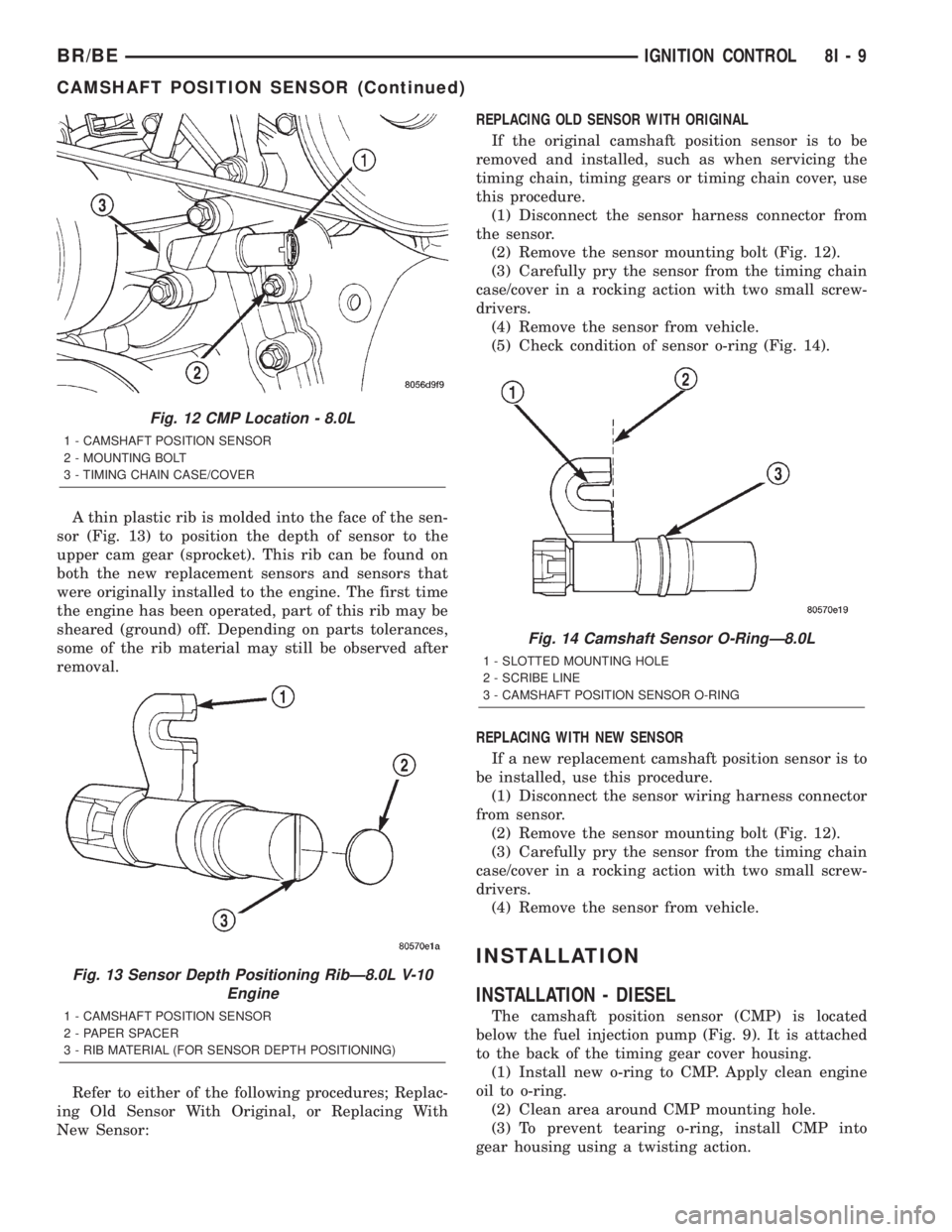
A thin plastic rib is molded into the face of the sen-
sor (Fig. 13) to position the depth of sensor to the
upper cam gear (sprocket). This rib can be found on
both the new replacement sensors and sensors that
were originally installed to the engine. The first time
the engine has been operated, part of this rib may be
sheared (ground) off. Depending on parts tolerances,
some of the rib material may still be observed after
removal.
Refer to either of the following procedures; Replac-
ing Old Sensor With Original, or Replacing With
New Sensor:REPLACING OLD SENSOR WITH ORIGINAL
If the original camshaft position sensor is to be
removed and installed, such as when servicing the
timing chain, timing gears or timing chain cover, use
this procedure.
(1) Disconnect the sensor harness connector from
the sensor.
(2) Remove the sensor mounting bolt (Fig. 12).
(3) Carefully pry the sensor from the timing chain
case/cover in a rocking action with two small screw-
drivers.
(4) Remove the sensor from vehicle.
(5) Check condition of sensor o-ring (Fig. 14).
REPLACING WITH NEW SENSOR
If a new replacement camshaft position sensor is to
be installed, use this procedure.
(1) Disconnect the sensor wiring harness connector
from sensor.
(2) Remove the sensor mounting bolt (Fig. 12).
(3) Carefully pry the sensor from the timing chain
case/cover in a rocking action with two small screw-
drivers.
(4) Remove the sensor from vehicle.
INSTALLATION
INSTALLATION - DIESEL
The camshaft position sensor (CMP) is located
below the fuel injection pump (Fig. 9). It is attached
to the back of the timing gear cover housing.
(1) Install new o-ring to CMP. Apply clean engine
oil to o-ring.
(2) Clean area around CMP mounting hole.
(3) To prevent tearing o-ring, install CMP into
gear housing using a twisting action.
Fig. 12 CMP Location - 8.0L
1 - CAMSHAFT POSITION SENSOR
2 - MOUNTING BOLT
3 - TIMING CHAIN CASE/COVER
Fig. 13 Sensor Depth Positioning RibÐ8.0L V-10
Engine
1 - CAMSHAFT POSITION SENSOR
2 - PAPER SPACER
3 - RIB MATERIAL (FOR SENSOR DEPTH POSITIONING)
Fig. 14 Camshaft Sensor O-RingÐ8.0L
1 - SLOTTED MOUNTING HOLE
2 - SCRIBE LINE
3 - CAMSHAFT POSITION SENSOR O-RING
BR/BEIGNITION CONTROL 8I - 9
CAMSHAFT POSITION SENSOR (Continued)
Page 470 of 2255
INSTALLATION
If engine has been cranked while distributor is
removed, establish the relationship between distribu-
tor shaft and number one piston position as follows:
Rotate crankshaft in a clockwise direction, as
viewed from front, until number one cylinder piston
is at top of compression stroke (compression should
be felt on finger with number one spark plug
removed). Then continue to slowly rotate engine
clockwise until indicating mark (Fig. 18) is aligned to
0 degree (TDC) mark on timing chain cover.
(1) Clean top of cylinder block for a good seal
between distributor base and block.
(2) Lightly oil the rubber o-ring seal on the distrib-
utor housing.
(3) Install rotor to distributor shaft.
(4) Position distributor into engine to its original
position. Engage tongue of distributor shaft with slot
in distributor oil pump drive gear. Position rotor to
the number one spark plug cable position.
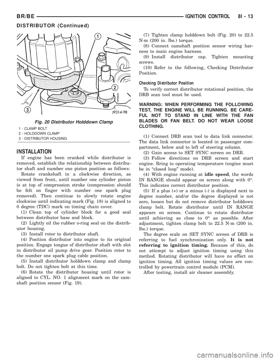
(5) Install distributor holddown clamp and clamp
bolt. Do not tighten bolt at this time.
(6) Rotate the distributor housing until rotor is
aligned to CYL. NO. 1 alignment mark on the cam-
shaft position sensor (Fig. 19).(7) Tighten clamp holddown bolt (Fig. 20) to 22.5
N´m (200 in. lbs.) torque.
(8) Connect camshaft position sensor wiring har-
ness to main engine harness.
(9) Install distributor cap. Tighten mounting
screws.
(10) Refer to the following, Checking Distributor
Position.
Checking Distributor Position
To verify correct distributor rotational position, the
DRB scan tool must be used.
WARNING: WHEN PERFORMING THE FOLLOWING
TEST, THE ENGINE WILL BE RUNNING. BE CARE-
FUL NOT TO STAND IN LINE WITH THE FAN
BLADES OR FAN BELT. DO NOT WEAR LOOSE
CLOTHING.
(1) Connect DRB scan tool to data link connector.
The data link connector is located in passenger com-
partment, below and to left of steering column.
(2) Gain access to SET SYNC screen on DRB.
(3) Follow directions on DRB screen and start
engine. Bring to operating temperature (engine must
be in ªclosed loopº mode).
(4) With engine running atidle speed, the words
IN RANGE should appear on screen along with 0É.
This indicates correct distributor position.
(5) If a plus (+) or a minus (-) is displayed next to
degree number, and/or the degree displayed is not
zero, loosen but do not remove distributor holddown
clamp bolt. Rotate distributor until IN RANGE
appears on screen. Continue to rotate distributor
until achieving as close to 0É as possible. After
adjustment, tighten clamp bolt to 22.5 N´m (200 in.
lbs.) torque.
The degree scale on SET SYNC screen of DRB is
referring to fuel synchronization only.It is not
referring to ignition timing.Because of this, do
not attempt to adjust ignition timing using this
method. Rotating distributor will have no effect on
ignition timing. All ignition timing values are con-
trolled by powertrain control module (PCM).
After testing, install air cleaner assembly.
Fig. 20 Distributor Holddown Clamp
1 - CLAMP BOLT
2 - HOLDDOWN CLAMP
3 - DISTRIBUTOR HOUSING
BR/BEIGNITION CONTROL 8I - 13
DISTRIBUTOR (Continued)
Page 678 of 2255
8W-02 COMPONENT INDEX
Component Page
4WD Switch.......................... 8W-31
A/C Compressor Clutch Relay............ 8W-42
A/C Compressor Clutch................. 8W-42
A/C- Heater Control.................... 8W-42
A/C Heater Temperature Select........... 8W-42
A/C High Pressure Switch............... 8W-42
A/C Low Pressure Switch................ 8W-42
Accelerator Pedal Position Sensor......... 8W-30
Aftermarket Center High Mounted Stop
Lamp............................. 8W-51
Aftermarket Trailer Tow Connector........ 8W-54
Airbag Control Module.................. 8W-43
Ambient Temperature Sensor............ 8W-49
Ash Receiver Lamp.................... 8W-44
Automatic Day/Night Mirror............. 8W-49
Automatic Shut Down Relay............. 8W-30
Auxiliary Battery...................... 8W-20
Back-Up Lamp Switch.................. 8W-51
Back-Up Lamp........................ 8W-51
Battery Temperature Sensor............. 8W-30
Battery............................. 8W-20
Blend Door Actuator................... 8W-42
Blower Motor Relay.................... 8W-42
Blower Motor Resistor Block............. 8W-42
Blower Motor......................... 8W-42
Brake Lamp Switch.................... 8W-51
Brake Pressure Switch............... 8W-34, 35
Bypass Jumper....................... 8W-21
Camshaft Position Sensor............... 8W-30
Capacitor......................... 8W-10, 30
Cargo Lamps........................ 8W-44
Center High Mounted Stop Lamps........ 8W-51
Center Identification Lamp.............. 8W-50
Central Timer Module.................. 8W-45
Cigar Lighter......................... 8W-41
Circuit Breakers...................... 8W-12
Clockspring.................. 8W-33, 41, 43, 47
Clutch Pedal Position Switch............. 8W-21
Combination Flasher................... 8W-52
Controller Antilock Brake............ 8W-34, 35
Crankshaft Position Sensor.............. 8W-30
Cummins Bus........................ 8W-18
Cup Holder Lamp..................... 8W-44
Data Link Connector................... 8W-18
Daytime Running Lamp Module.......... 8W-50
Dome Lamp.......................... 8W-44
Driver Airbag......................... 8W-43
Driver Cylinder Lock Switch............. 8W-39
Driver Door Ajar Switch................ 8W-45
Driver Door Lock Motor................. 8W-61
Driver Door Window/Lock Switch...... 8W-60, 61
Driver Heated Seat Cushion............. 8W-63Component Page
Driver Heated Seat Switch.............. 8W-63
Driver Lumbar Motor.................. 8W-63
Driver Power Seat Front Vertical Motor.... 8W-63
Driver Power Seat Horizontal Motor....... 8W-63
Driver Power Seat Rear Vertical Motor..... 8W-63
Driver Power Seat Switch............... 8W-63
Driver Power Window Motor............. 8W-60
Electric Brake Provision................ 8W-54
Engine Control Module................. 8W-30
Engine Coolant Temperature Sensor....... 8W-30
Engine Oil Pressure Sensor.............. 8W-30
Engine Starter Motor Relay.............. 8W-21
Engine Starter Motor................... 8W-21
EVAP/Purge Solenoid................... 8W-30
Fender Lamp......................... 8W-51
Fog Lamp Relay....................... 8W-50
Fog Lamp............................ 8W-50
Fuel Heater Relay..................... 8W-30
Fuel Heater........................ 8W-30-36
Fuel Injection Pump................... 8W-30
Fuel Injectors......................... 8W-30
Fuel Pump Module.................... 8W-30
Fuel Pump Relay...................... 8W-30
Fuel Tank Module..................... 8W-30
Fuel Transfer Pump.................... 8W-30
Fuses (JB)........................... 8W-12
Fuses (PDC).......................... 8W-10
Fusible Link....................... 8W-20, 30
Grounds............................. 8W-15
Generator............................ 8W-20
Glove Box Lamp And Switch............. 8W-44
Headlamp Beam Select Switch........... 8W-50
Headlamp Switch...................... 8W-50
Headlamp........................... 8W-50
Heated Mirror Relay................... 8W-62
Heated Mirror Switch.................. 8W-62
Heated Seat Relay..................... 8W-12
High Note Horn....................... 8W-41
Horn Relay.......................... 8W-41
Horn Switch.......................... 8W-41
Idle Air Control Motor.................. 8W-30
Ignition Coils......................... 8W-30
Ignition Switch....................... 8W-10
Instrument Cluster.................... 8W-40
Intake Air Heater Relays................ 8W-30
Intake Air Heater..................... 8W-30
Intake Air Temperature Sensor........... 8W-30
Intermittent Wiper Switch............... 8W-53
Joint Connectors....... 8W-10, 12, 15, 30, 34, 35,
40, 44, 45, 51, 53, 54, 70
Junction Block........................ 8W-12
Leak Detection Pump.................. 8W-30
BR/BE8W-02 COMPONENT INDEX 8W - 02 - 1
Page 679 of 2255

Component Page
License Lamp......................... 8W-51
Low Note Horn....................... 8W-41
Manifold Absolute Pressure Sensor........ 8W-30
Outboard Clearance Lamps.............. 8W-50
Outboard Headlamps................... 8W-50
Outboard Identification Lamps........... 8W-50
Output Speed Sensor................... 8W-31
Overdrive Switch...................... 8W-31
Overhead Console..................... 8W-49
Oxygen Sensors....................... 8W-30
Oxygen Sensor Downstream Relay........ 8W-30
Park Brake Switch.................. 8W-40, 50
Park/Neutral Position Switch.......... 8W-30, 51
Park/Turn Signal Lamp................. 8W-52
Passenger Airbag On/Off Switch.......... 8W-43
Passenger Airbag...................... 8W-43
Passenger Cylinder Lock Switch.......... 8W-39
Passenger Door Ajar Switch.............. 8W-45
Passenger Door Lock Motor.............. 8W-61
Passenger Door Window/Lock Switch.... 8W-60, 61
Passenger Heated Seat Cushion.......... 8W-63
Passenger Heated Seat Switch........... 8W-63
Passenger Lumbar Motor................ 8W-63
Passenger Power Seat Front Vertical
Motor............................. 8W-63
Passenger Power Seat Horizontal Motor.... 8W-63
Passenger Power Seat Rear Vertical Motor . . 8W-63
Passenger Power Seat Switch............ 8W-63
Passenger Power Window Motor.......... 8W-60
Power Distribution Center............... 8W-10
Power Mirror Switch................... 8W-62Component Page
Power Mirror......................... 8W-62
Power Outlet......................... 8W-41
Powertrain Control Module.............. 8W-30
PTO Switch.......................... 8W-30
Quad High Beam Relay................. 8W-50
Radio Choke Relay..................... 8W-47
Radio............................... 8W-47
Rear Wheel Speed Sensor............ 8W-34, 35
Remote Radio Switch................... 8W-47
Splices.............................. 8W-70
Seat Belt Switch...................... 8W-40
Seat Heat Interface Module.............. 8W-63
Security Relay........................ 8W-39
Speakers............................ 8W-47
Speed Control Servo................... 8W-33
Speed Control Switches................. 8W-33
Tail/Stop/Turn Signal Lamp.............. 8W-51
Tailgate Lamps....................... 8W-51
Throttle Position Sensor................ 8W-30
Trailer Tow Connector.................. 8W-54
Trailer Tow Relay...................... 8W-54
Transmission Control Relay.............. 8W-31
Transmission Solenoid Assembly.......... 8W-31
Turn Signal/Hazard Switch.............. 8W-52
Underhood Lamp...................... 8W-44
Visor/Vanity Lamps.................... 8W-44
Washer Fluid Level Switch.............. 8W-40
Water In Fuel Sensor................... 8W-30
Wheel Speed Sensor.................... 8W-35
Windshield Washer Pump............... 8W-53
Wiper Motor Relay..................... 8W-53
8W - 02 - 2 8W-02 COMPONENT INDEXBR/BE