2002 DODGE RAM compression ratio
[x] Cancel search: compression ratioPage 1171 of 2255
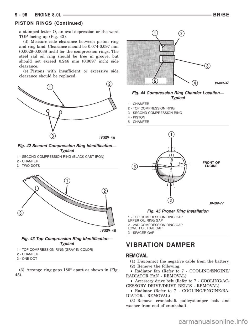
a stamped letter O, an oval depression or the word
TOP facing up (Fig. 43).
(d) Measure side clearance between piston ring
and ring land. Clearance should be 0.074-0.097 mm
(0.0029-0.0038 inch) for the compression rings. The
steel rail oil ring should be free in groove, but
should not exceed 0.246 mm (0.0097 inch) side
clearance.
(e) Pistons with insufficient or excessive side
clearance should be replaced.
(3) Arrange ring gaps 180É apart as shown in (Fig.
45).
VIBRATION DAMPER
REMOVAL
(1) Disconnect the negative cable from the battery.
(2) Remove the following:
²Radiator fan (Refer to 7 - COOLING/ENGINE/
RADIATOR FAN - REMOVAL)
²Accessory drive belt (Refer to 7 - COOLING/AC-
CESSORY DRIVE/DRIVE BELTS - REMOVAL)
²Radiator (Refer to 7 - COOLING/ENGINE/RA-
DIATOR - REMOVAL)
(3) Remove crankshaft pulley/damper bolt and
washer from end of crankshaft.
Fig. 42 Second Compression Ring IdentificationÐ
Typical
1 - SECOND COMPRESSION RING (BLACK CAST IRON)
2 - CHAMFER
3 - TWO DOTS
Fig. 43 Top Compression Ring IdentificationÐ
Typical
1 - TOP COMPRESSION RING (GRAY IN COLOR)
2 - CHAMFER
3 - ONE DOT
Fig. 44 Compression Ring Chamfer LocationÐ
Typical
1 - CHAMFER
2 - TOP COMPRESSION RING
3 - SECOND COMPRESSION RING
4 - PISTON
5 - CHAMFER
Fig. 45 Proper Ring Installation
1 - TOP COMPRESSION RING GAP
UPPER OIL RING GAP
2 - 2ND COMPRESSION RING GAP
LOWER OIL RAIL GAP
3 - SPACER GAP
9 - 96 ENGINE 8.0LBR/BE
PISTON RINGS (Continued)
Page 1192 of 2255
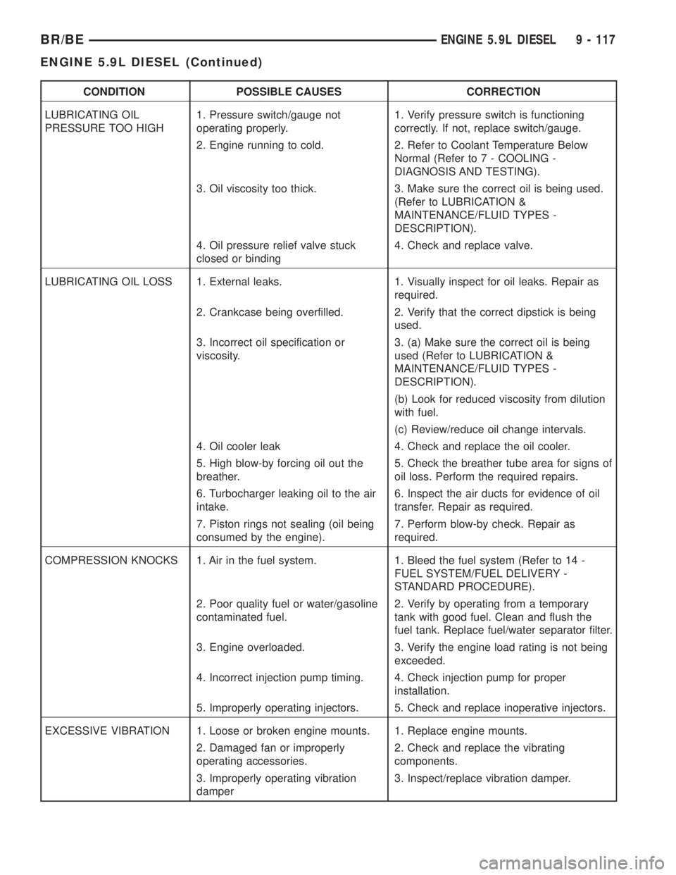
CONDITION POSSIBLE CAUSES CORRECTION
LUBRICATING OIL
PRESSURE TOO HIGH1. Pressure switch/gauge not
operating properly.1. Verify pressure switch is functioning
correctly. If not, replace switch/gauge.
2. Engine running to cold. 2. Refer to Coolant Temperature Below
Normal (Refer to 7 - COOLING -
DIAGNOSIS AND TESTING).
3. Oil viscosity too thick. 3. Make sure the correct oil is being used.
(Refer to LUBRICATION &
MAINTENANCE/FLUID TYPES -
DESCRIPTION).
4. Oil pressure relief valve stuck
closed or binding4. Check and replace valve.
LUBRICATING OIL LOSS 1. External leaks. 1. Visually inspect for oil leaks. Repair as
required.
2. Crankcase being overfilled. 2. Verify that the correct dipstick is being
used.
3. Incorrect oil specification or
viscosity.3. (a) Make sure the correct oil is being
used (Refer to LUBRICATION &
MAINTENANCE/FLUID TYPES -
DESCRIPTION).
(b) Look for reduced viscosity from dilution
with fuel.
(c) Review/reduce oil change intervals.
4. Oil cooler leak 4. Check and replace the oil cooler.
5. High blow-by forcing oil out the
breather.5. Check the breather tube area for signs of
oil loss. Perform the required repairs.
6. Turbocharger leaking oil to the air
intake.6. Inspect the air ducts for evidence of oil
transfer. Repair as required.
7. Piston rings not sealing (oil being
consumed by the engine).7. Perform blow-by check. Repair as
required.
COMPRESSION KNOCKS 1. Air in the fuel system. 1. Bleed the fuel system (Refer to 14 -
FUEL SYSTEM/FUEL DELIVERY -
STANDARD PROCEDURE).
2. Poor quality fuel or water/gasoline
contaminated fuel.2. Verify by operating from a temporary
tank with good fuel. Clean and flush the
fuel tank. Replace fuel/water separator filter.
3. Engine overloaded. 3. Verify the engine load rating is not being
exceeded.
4. Incorrect injection pump timing. 4. Check injection pump for proper
installation.
5. Improperly operating injectors. 5. Check and replace inoperative injectors.
EXCESSIVE VIBRATION 1. Loose or broken engine mounts. 1. Replace engine mounts.
2. Damaged fan or improperly
operating accessories.2. Check and replace the vibrating
components.
3. Improperly operating vibration
damper3. Inspect/replace vibration damper.
BR/BEENGINE 5.9L DIESEL 9 - 117
ENGINE 5.9L DIESEL (Continued)
Page 1202 of 2255
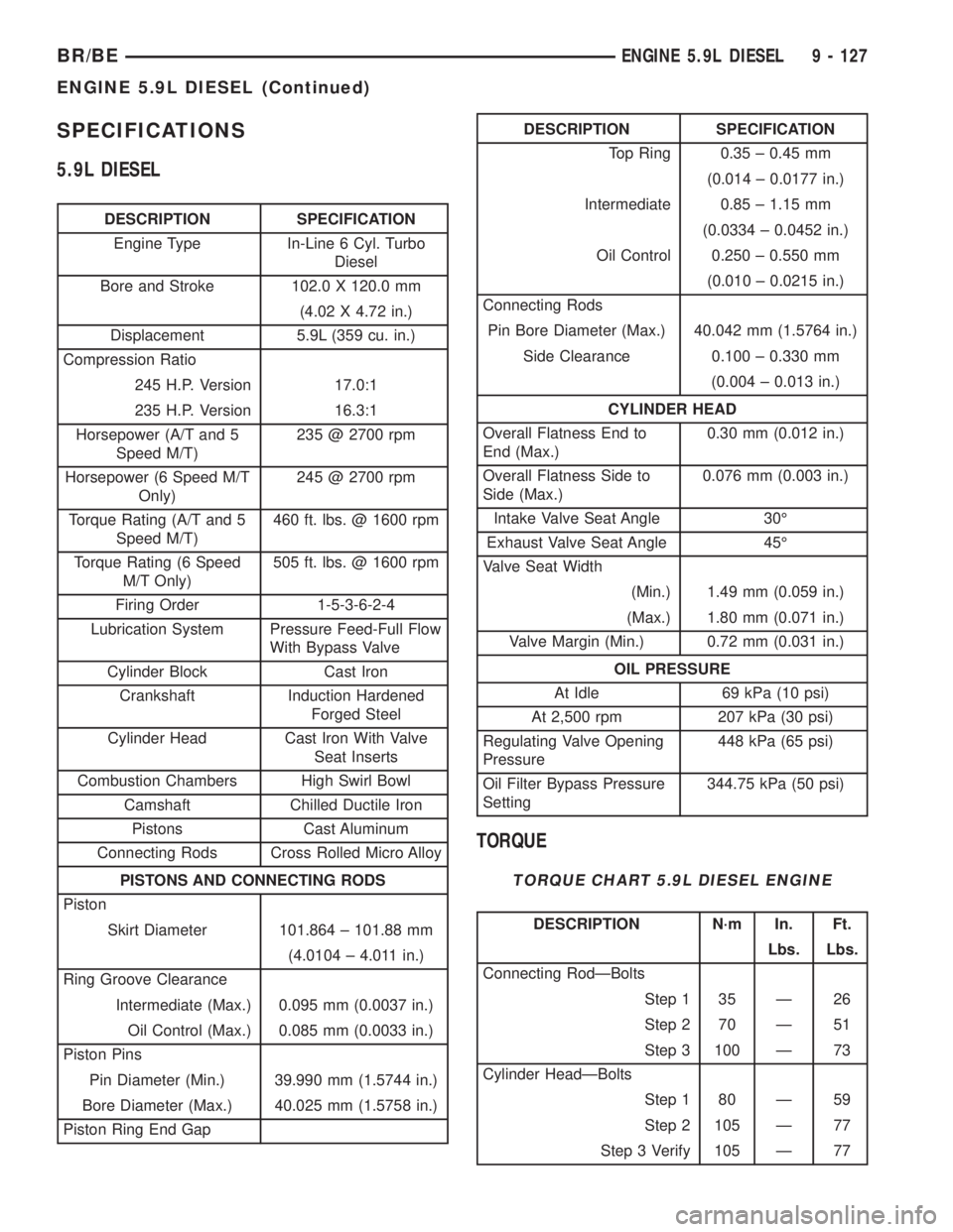
SPECIFICATIONS
5.9L DIESEL
DESCRIPTION SPECIFICATION
Engine Type In-Line 6 Cyl. Turbo
Diesel
Bore and Stroke 102.0 X 120.0 mm
(4.02 X 4.72 in.)
Displacement 5.9L (359 cu. in.)
Compression Ratio
245 H.P. Version 17.0:1
235 H.P. Version 16.3:1
Horsepower (A/T and 5
Speed M/T)235 @ 2700 rpm
Horsepower (6 Speed M/T
Only)245 @ 2700 rpm
Torque Rating (A/T and 5
Speed M/T)460 ft. lbs. @ 1600 rpm
Torque Rating (6 Speed
M/T Only)505 ft. lbs. @ 1600 rpm
Firing Order 1-5-3-6-2-4
Lubrication System Pressure Feed-Full Flow
With Bypass Valve
Cylinder Block Cast Iron
Crankshaft Induction Hardened
Forged Steel
Cylinder Head Cast Iron With Valve
Seat Inserts
Combustion Chambers High Swirl Bowl
Camshaft Chilled Ductile Iron
Pistons Cast Aluminum
Connecting Rods Cross Rolled Micro Alloy
PISTONS AND CONNECTING RODS
Piston
Skirt Diameter 101.864 ± 101.88 mm
(4.0104 ± 4.011 in.)
Ring Groove Clearance
Intermediate (Max.) 0.095 mm (0.0037 in.)
Oil Control (Max.) 0.085 mm (0.0033 in.)
Piston Pins
Pin Diameter (Min.) 39.990 mm (1.5744 in.)
Bore Diameter (Max.) 40.025 mm (1.5758 in.)
Piston Ring End Gap
DESCRIPTION SPECIFICATION
Top Ring 0.35 ± 0.45 mm
(0.014 ± 0.0177 in.)
Intermediate 0.85 ± 1.15 mm
(0.0334 ± 0.0452 in.)
Oil Control 0.250 ± 0.550 mm
(0.010 ± 0.0215 in.)
Connecting Rods
Pin Bore Diameter (Max.) 40.042 mm (1.5764 in.)
Side Clearance 0.100 ± 0.330 mm
(0.004 ± 0.013 in.)
CYLINDER HEAD
Overall Flatness End to
End (Max.)0.30 mm (0.012 in.)
Overall Flatness Side to
Side (Max.)0.076 mm (0.003 in.)
Intake Valve Seat Angle 30É
Exhaust Valve Seat Angle 45É
Valve Seat Width
(Min.) 1.49 mm (0.059 in.)
(Max.) 1.80 mm (0.071 in.)
Valve Margin (Min.) 0.72 mm (0.031 in.)
OIL PRESSURE
At Idle 69 kPa (10 psi)
At 2,500 rpm 207 kPa (30 psi)
Regulating Valve Opening
Pressure448 kPa (65 psi)
Oil Filter Bypass Pressure
Setting344.75 kPa (50 psi)
TORQUE
TORQUE CHART 5.9L DIESEL ENGINE
DESCRIPTION N´m In. Ft.
Lbs. Lbs.
Connecting RodÐBolts
Step 1 35 Ð 26
Step 2 70 Ð 51
Step 3 100 Ð 73
Cylinder HeadÐBolts
Step 1 80 Ð 59
Step 2 105 Ð 77
Step 3 Verify 105 Ð 77
BR/BEENGINE 5.9L DIESEL 9 - 127
ENGINE 5.9L DIESEL (Continued)
Page 1281 of 2255
(4) Connect the DRBIIItto the pressure trans-
ducer following the instructions supplied with the
DRB IIIt.
(5) Enter DRBIIItinto pressure reading mode and
test drive vehicle.
(6) The turbocharger boost pressure must be
between 110 - 138 kpa (16 - 20 psi.). If pressure read-
ings are lower than 110 kpa (16 psi.) inspect for the
following:
²Restricted air inlet system
²Leak in the charge air cooler system (Refer to 11
- EXHAUST SYSTEM/TURBOCHARGER SYSTEM/
CHARGE AIR COOLER AND PLUMBING - DIAG-
NOSIS AND TESTING)
²Turbocharger wastegate broken or misadjusted
²Turbocharger damaged (Refer to 11 - EXHAUST
SYSTEM/TURBOCHARGER SYSTEM/TURBO-
CHARGER - INSPECTION)
TURBOCHARGER
DESCRIPTION
The turbocharger is an exhaust-driven super-
charger which increases the pressure and density of
the air entering the engine. With the increase of air
entering the engine, more fuel can be injected into
the cylinders, which creates more power during com-
bustion.
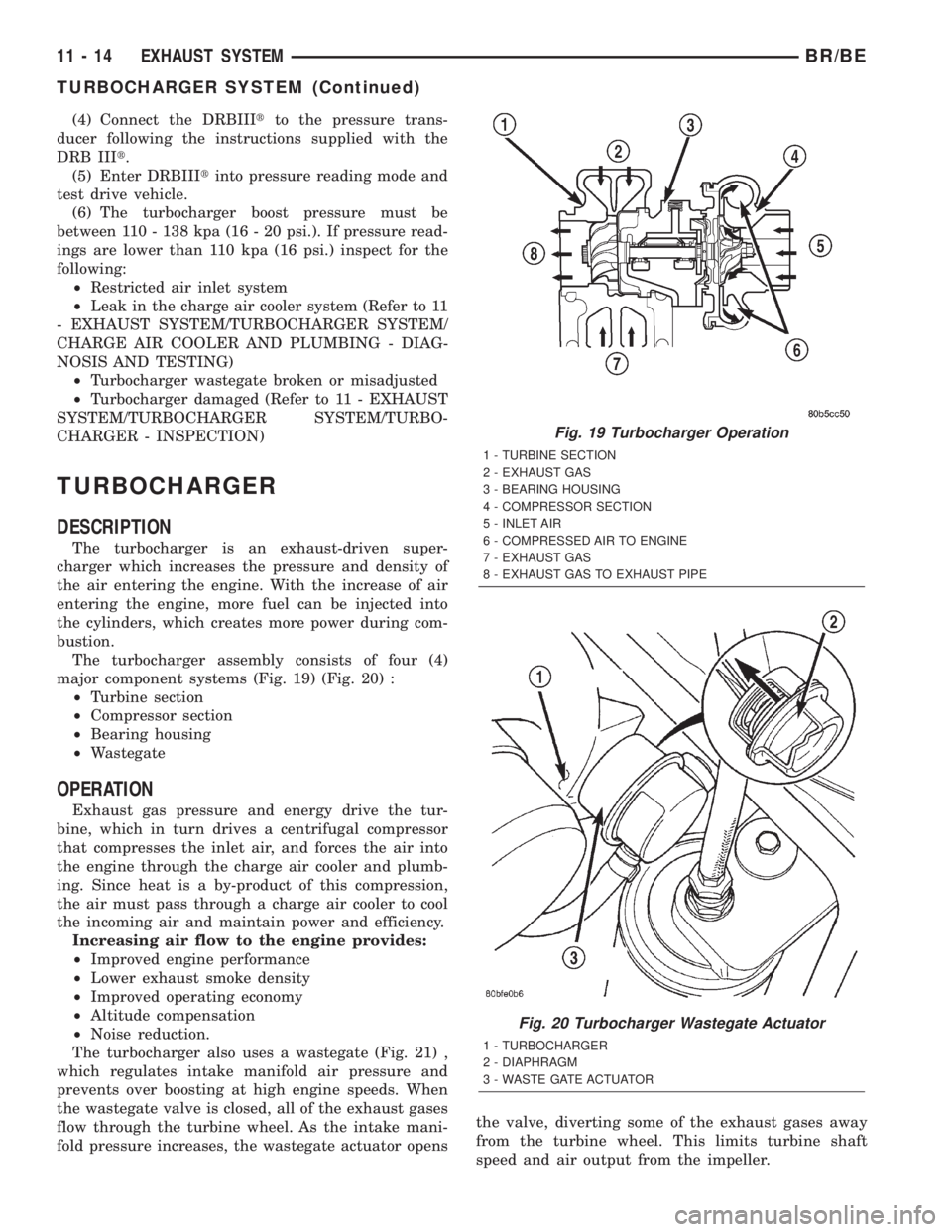
The turbocharger assembly consists of four (4)
major component systems (Fig. 19) (Fig. 20) :
²Turbine section
²Compressor section
²Bearing housing
²Wastegate
OPERATION
Exhaust gas pressure and energy drive the tur-
bine, which in turn drives a centrifugal compressor
that compresses the inlet air, and forces the air into
the engine through the charge air cooler and plumb-
ing. Since heat is a by-product of this compression,
the air must pass through a charge air cooler to cool
the incoming air and maintain power and efficiency.
Increasing air flow to the engine provides:
²Improved engine performance
²Lower exhaust smoke density
²Improved operating economy
²Altitude compensation
²Noise reduction.
The turbocharger also uses a wastegate (Fig. 21) ,
which regulates intake manifold air pressure and
prevents over boosting at high engine speeds. When
the wastegate valve is closed, all of the exhaust gases
flow through the turbine wheel. As the intake mani-
fold pressure increases, the wastegate actuator opensthe valve, diverting some of the exhaust gases away
from the turbine wheel. This limits turbine shaft
speed and air output from the impeller.
Fig. 19 Turbocharger Operation
1 - TURBINE SECTION
2 - EXHAUST GAS
3 - BEARING HOUSING
4 - COMPRESSOR SECTION
5 - INLET AIR
6 - COMPRESSED AIR TO ENGINE
7 - EXHAUST GAS
8 - EXHAUST GAS TO EXHAUST PIPE
Fig. 20 Turbocharger Wastegate Actuator
1 - TURBOCHARGER
2 - DIAPHRAGM
3 - WASTE GATE ACTUATOR
11 - 14 EXHAUST SYSTEMBR/BE
TURBOCHARGER SYSTEM (Continued)
Page 1645 of 2255
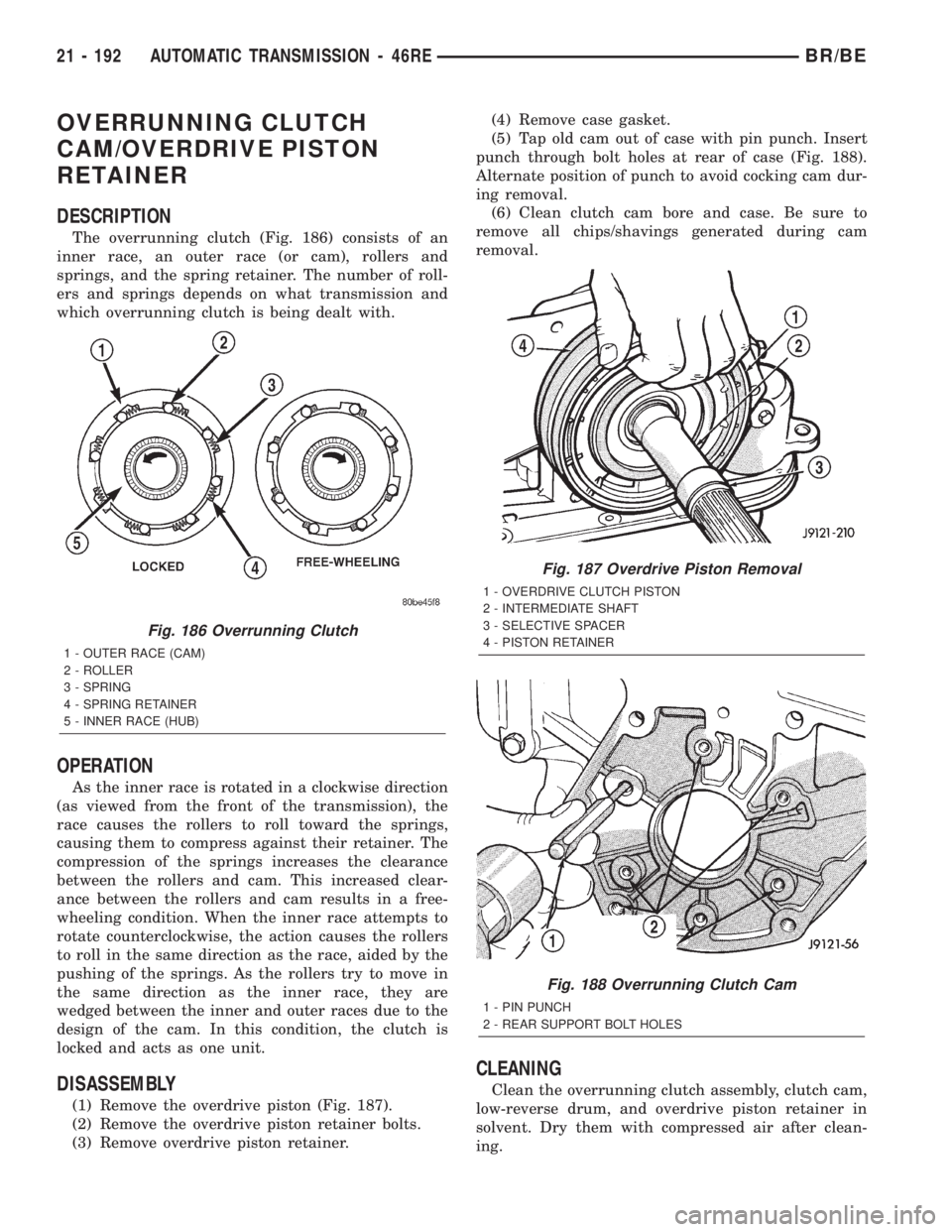
OVERRUNNING CLUTCH
CAM/OVERDRIVE PISTON
RETAINER
DESCRIPTION
The overrunning clutch (Fig. 186) consists of an
inner race, an outer race (or cam), rollers and
springs, and the spring retainer. The number of roll-
ers and springs depends on what transmission and
which overrunning clutch is being dealt with.
OPERATION
As the inner race is rotated in a clockwise direction
(as viewed from the front of the transmission), the
race causes the rollers to roll toward the springs,
causing them to compress against their retainer. The
compression of the springs increases the clearance
between the rollers and cam. This increased clear-
ance between the rollers and cam results in a free-
wheeling condition. When the inner race attempts to
rotate counterclockwise, the action causes the rollers
to roll in the same direction as the race, aided by the
pushing of the springs. As the rollers try to move in
the same direction as the inner race, they are
wedged between the inner and outer races due to the
design of the cam. In this condition, the clutch is
locked and acts as one unit.
DISASSEMBLY
(1) Remove the overdrive piston (Fig. 187).
(2) Remove the overdrive piston retainer bolts.
(3) Remove overdrive piston retainer.(4) Remove case gasket.
(5) Tap old cam out of case with pin punch. Insert
punch through bolt holes at rear of case (Fig. 188).
Alternate position of punch to avoid cocking cam dur-
ing removal.
(6) Clean clutch cam bore and case. Be sure to
remove all chips/shavings generated during cam
removal.
CLEANING
Clean the overrunning clutch assembly, clutch cam,
low-reverse drum, and overdrive piston retainer in
solvent. Dry them with compressed air after clean-
ing.
Fig. 186 Overrunning Clutch
1 - OUTER RACE (CAM)
2 - ROLLER
3 - SPRING
4 - SPRING RETAINER
5 - INNER RACE (HUB)
Fig. 187 Overdrive Piston Removal
1 - OVERDRIVE CLUTCH PISTON
2 - INTERMEDIATE SHAFT
3 - SELECTIVE SPACER
4 - PISTON RETAINER
Fig. 188 Overrunning Clutch Cam
1 - PIN PUNCH
2 - REAR SUPPORT BOLT HOLES
21 - 192 AUTOMATIC TRANSMISSION - 46REBR/BE
Page 1816 of 2255
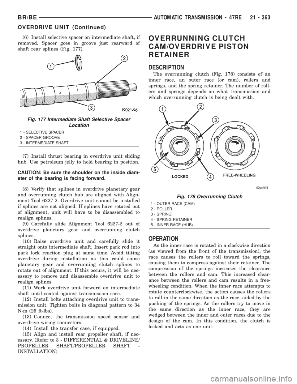
(6) Install selective spacer on intermediate shaft, if
removed. Spacer goes in groove just rearward of
shaft rear splines (Fig. 177).
(7) Install thrust bearing in overdrive unit sliding
hub. Use petroleum jelly to hold bearing in position.
CAUTION: Be sure the shoulder on the inside diam-
eter of the bearing is facing forward.
(8) Verify that splines in overdrive planetary gear
and overrunning clutch hub are aligned with Align-
ment Tool 6227-2. Overdrive unit cannot be installed
if splines are not aligned. If splines have rotated out
of alignment, unit will have to be disassembled to
realign splines.
(9) Carefully slide Alignment Tool 6227-2 out of
overdrive planetary gear and overrunning clutch
splines.
(10) Raise overdrive unit and carefully slide it
straight onto intermediate shaft. Insert park rod into
park lock reaction plug at same time. Avoid tilting
overdrive during installation as this could cause
planetary gear and overrunning clutch splines to
rotate out of alignment. If this occurs, it will be nec-
essary to remove and disassemble overdrive unit to
realign splines.
(11) Work overdrive unit forward on intermediate
shaft until seated against transmission case.
(12) Install bolts attaching overdrive unit to trans-
mission unit. Tighten bolts in diagonal pattern to 34
N´m (25 ft-lbs).
(13) Connect the transmission speed sensor and
overdrive wiring connectors.
(14) Install the transfer case, if equipped.
(15) Align and install rear propeller shaft, if nec-
essary. (Refer to 3 - DIFFERENTIAL & DRIVELINE/
PROPELLER SHAFT/PROPELLER SHAFT -
INSTALLATION)OVERRUNNING CLUTCH
CAM/OVERDRIVE PISTON
RETAINER
DESCRIPTION
The overrunning clutch (Fig. 178) consists of an
inner race, an outer race (or cam), rollers and
springs, and the spring retainer. The number of roll-
ers and springs depends on what transmission and
which overrunning clutch is being dealt with.
OPERATION
As the inner race is rotated in a clockwise direction
(as viewed from the front of the transmission), the
race causes the rollers to roll toward the springs,
causing them to compress against their retainer. The
compression of the springs increases the clearance
between the rollers and cam. This increased clear-
ance between the rollers and cam results in a free-
wheeling condition. When the inner race attempts to
rotate counterclockwise, the action causes the rollers
to roll in the same direction as the race, aided by the
pushing of the springs. As the rollers try to move in
the same direction as the inner race, they are
wedged between the inner and outer races due to the
design of the cam. In this condition, the clutch is
locked and acts as one unit.
Fig. 177 Intermediate Shaft Selective Spacer
Location
1 - SELECTIVE SPACER
2 - SPACER GROOVE
3 - INTERMEDIATE SHAFT
Fig. 178 Overrunning Clutch
1 - OUTER RACE (CAM)
2 - ROLLER
3 - SPRING
4 - SPRING RETAINER
5 - INNER RACE (HUB)
BR/BEAUTOMATIC TRANSMISSION - 47RE 21 - 363
OVERDRIVE UNIT (Continued)
Page 2203 of 2255
²Absolute MAP When Misfire OccurredÐ
The stored MAP reading at the time of failure.
Informs the user at what engine load the failure
occurred.
²Absolute MAPÐ A live reading of engine load
to aid the user in accessing the Similar Conditions
Window.
²RPM When Misfire OccurredÐ The stored
RPM reading at the time of failure. Informs the user
at what engine RPM the failure occurred.
²Engine RPMÐ A live reading of engine RPM
to aid the user in accessing the Similar Conditions
Window.
²Adaptive Memory FactorÐ The PCM utilizes
both Short Term Compensation and Long Term Adap-
tive to calculate the Adaptive Memory Factor for
total fuel correction.
²200 Rev CounterÐ Counts 0±100 720 degree
cycles.
²SCW Cat 200 Rev CounterÐ Counts when in
similar conditions.
²SCW FTP 1000 Rev CounterÐ Counts 0±4
when in similar conditions.
²Misfire Good Trip CounterÐ Counts up to
three to turn OFF the MIL.
²Misfire DataÐ Data collected during test.
²Test Done This TripÐ Indicates YES when the
test is done.
OPERATION - NON-MONITORED CIRCUITS -
GAS ENGINES
The PCM does not monitor the following circuits,
systems and conditions that could have malfunctions
causing driveability problems. The PCM might not
store diagnostic trouble codes for these conditions.
However, problems with these systems may cause the
PCM to store diagnostic trouble codes for other sys-
tems or components.EXAMPLE:a fuel pressure
problem will not register a fault directly, but could
cause a rich/lean condition or misfire. This could
cause the PCM to store an oxygen sensor or misfire
diagnostic trouble code
FUEL PRESSURE
The fuel pressure regulator controls fuel system
pressure. The PCM cannot detect a clogged fuel
pump inlet filter, clogged in-line fuel filter, or a
pinched fuel supply or return line. However, these
could result in a rich or lean condition causing the
PCM to store an oxygen sensor or fuel system diag-
nostic trouble code.
SECONDARY IGNITION CIRCUIT
The PCM cannot detect an inoperative ignition coil,
fouled or worn spark plugs, ignition cross firing, or
open spark plug cables.CYLINDER COMPRESSION
The PCM cannot detect uneven, low, or high engine
cylinder compression.
EXHAUST SYSTEM
The PCM cannot detect a plugged, restricted or
leaking exhaust system, although it may set a fuel
system fault.
FUEL INJECTOR MECHANICAL MALFUNCTIONS
The PCM cannot determine if a fuel injector is
clogged, the needle is sticking or if the wrong injector
is installed. However, these could result in a rich or
lean condition causing the PCM to store a diagnostic
trouble code for either misfire, an oxygen sensor, or
the fuel system.
EXCESSIVE OIL CONSUMPTION
Although the PCM monitors engine exhaust oxygen
content when the system is in closed loop, it cannot
determine excessive oil consumption.
THROTTLE BODY AIR FLOW
The PCM cannot detect a clogged or restricted air
cleaner inlet or filter element.
VACUUM ASSIST
The PCM cannot detect leaks or restrictions in the
vacuum circuits of vacuum assisted engine control
system devices. However, these could cause the PCM
to store a MAP sensor diagnostic trouble code and
cause a high idle condition.
PCM SYSTEM GROUND
The PCM cannot determine a poor system ground.
However, one or more diagnostic trouble codes may
be generated as a result of this condition. The mod-
ule should be mounted to the body at all times, also
during diagnostic.
PCM CONNECTOR ENGAGEMENT
The PCM may not be able to determine spread or
damaged connector pins. However, it might store
diagnostic trouble codes as a result of spread connec-
tor pins.
OPERATION - NON-MONITORED CIRCUITS -
DIESEL
The PCM and/or the ECM will not monitor certain
malfunctioning circuits or components that could
cause driveability problems. Also, a Diagnostic Trou-
ble Code (DTC) might not be stored for these mal-
functions. However, problems with these circuits or
components may cause the PCM/ECM to store DTC's
for other circuits or components.EXAMPLES:A cyl-
inder with low compression will not set a DTC
25 - 24 EMISSIONS CONTROLBR/BE
EMISSIONS CONTROL (Continued)
Page 2224 of 2255
CLUTCH CAM/OVERDRIVE PISTON
RETAINER - INSPECTION,
OVERRUNNING...............21-193,21-364
CLUTCH CAM/OVERDRIVE PISTON
RETAINER - OPERATION,
OVERRUNNING...............21-192,21-363
CLUTCH COIL - DIAGNOSIS AND
TESTING, A/C COMPRESSOR...........24-13
CLUTCH DISC - INSTALLATION............6-8
CLUTCH DISC - REMOVAL...............6-7
CLUTCH HOUSING - DIAGNOSIS AND
TESTING.............................6-9
CLUTCH HOUSING - INSTALLATION.......6-11
CLUTCH HOUSING - REMOVAL...........6-11
CLUTCH PEDAL - INSTALLATION.........6-15
CLUTCH PEDAL - REMOVAL.............6-15
CLUTCH PEDAL POSITION SWITCH -
DESCRIPTION........................6-17
CLUTCH PEDAL POSITION SWITCH -
OPERATION..........................6-17
CLUTCH RELAY - DESCRIPTION, A/C
COMPRESSOR.......................24-17
CLUTCH RELAY - DIAGNOSIS AND
TESTING, A/C COMPRESSOR...........24-17
CLUTCH RELAY - INSTALLATION, A/C
COMPRESSOR.......................24-18
CLUTCH RELAY - OPERATION, A/C
COMPRESSOR.......................24-17
CLUTCH RELAY - REMOVAL, A/C
COMPRESSOR.......................24-18
CLUTCH RELEASE BEARING -
INSTALLATION........................6-12
CLUTCH RELEASE BEARING - REMOVAL . . . 6-12
COAT FINISH - DESCRIPTION, BASE
COAT/CLEAR.......................23-129
COAT FINISH - OPERATION, BASE
COAT/CLEAR.......................23-129
COAT HOOK - INSTALLATION..........23-125
COAT HOOK - REMOVAL..............23-124
COAT/CLEAR COAT FINISH -
DESCRIPTION, BASE.................23-129
COAT/CLEAR COAT FINISH - OPERATION,
BASE.............................23-129
CODE - DESCRIPTION, PAINT..........23-129
CODE PLATE - DESCRIPTION, BODY....Intro.-4
CODES - DESCRIPTION, DIAGNOSTIC
TROUBLE............................25-2
CODES, SPECIFICATIONS - 2002 BR/BE
PAINT COLOR......................23-129
COIL - DIAGNOSIS AND TESTING, A/C
COMPRESSOR CLUTCH...............24-13
COIL RESISTANCE, 5.9L ENGINES -
IGNITION............................8I-3
COIL RESISTANCE, 8.0L V-10 ENGINE -
IGNITION............................8I-4
COLOR CODES, SPECIFICATIONS - 2002
BR/BE PAINT.......................23-129
COLUMN - DESCRIPTION...............19-6
COLUMN OPENING COVER -
INSTALLATION, STEERING............23-114
COLUMN OPENING COVER - REMOVAL,
STEERING.........................23-113
COMBINATION FLASHER - DESCRIPTION . . . 8L-7
COMBINATION FLASHER -
INSTALLATION........................8L-9
COMBINATION FLASHER - OPERATION....8L-7
COMBINATION FLASHER - REMOVAL
......8L-8
COMBINATION VALVE - DESCRIPTION
......5-8
COMBINATION VALVE - DIAGNOSIS AND
TESTING
.............................5-9
COMBINATION VALVE - INSTALLATION
......5-9
COMBINATION VALVE - OPERATION
........5-9
COMBINATION VALVE - REMOVAL
.........5-9
COMBUSTION PRESSURE LEAKAGE -
DIAGNOSIS AND TESTING, CYLINDER
. . 9-64,9-9
COMPASS CALIBRATION - STANDARD
PROCEDURE
.........................8M-4
COMPASS DEMAGNETIZING -
STANDARD PROCEDURE
...............8M-5
COMPASS MINI-TRIP COMPUTER -
DIAGNOSIS AND TESTING
.............8M-10
COMPASS VARIATION ADJUSTMENT -
STANDARD PROCEDURE
...............8M-4
COMPASS/MINI-TRIP COMPUTER -
DESCRIPTION
........................8M-9
COMPASS/MINI-TRIP COMPUTER -
INSTALLATION
......................8M-11COMPASS/MINI-TRIP COMPUTER -
OPERATION.........................8M-9
COMPASS/MINI-TRIP COMPUTER -
REMOVAL..........................8M-11
COMPRESSION PRESSURE - DIAGNOSIS
AND TESTING, CYLINDER............9-64,9-9
COMPRESSOR - DESCRIPTION, A/C......24-46
COMPRESSOR - DIAGNOSIS AND
TESTING, A/C.......................24-47
COMPRESSOR - INSTALLATION, A/C.....24-48
COMPRESSOR - OPERATION, A/C........24-46
COMPRESSOR - REMOVAL, A/C.........24-47
COMPRESSOR CLUTCH - DESCRIPTION,
A/C................................24-11
COMPRESSOR CLUTCH - INSPECTION,
A/C................................24-15
COMPRESSOR CLUTCH - INSTALLATION,
A/C................................24-15
COMPRESSOR CLUTCH - OPERATION,
A/C................................24-13
COMPRESSOR CLUTCH - REMOVAL, A/C . . 24-13
COMPRESSOR CLUTCH BREAK-IN -
STANDARD PROCEDURE, A/C...........24-13
COMPRESSOR CLUTCH COIL -
DIAGNOSIS AND TESTING, A/C..........24-13
COMPRESSOR CLUTCH RELAY -
DESCRIPTION, A/C...................24-17
COMPRESSOR CLUTCH RELAY -
DIAGNOSIS AND TESTING, A/C..........24-17
COMPRESSOR CLUTCH RELAY -
INSTALLATION, A/C...................24-18
COMPRESSOR CLUTCH RELAY -
OPERATION, A/C.....................24-17
COMPRESSOR CLUTCH RELAY -
REMOVAL, A/C......................24-18
COMPUTER - DESCRIPTION, COMPASS/
MINI-TRIP..........................8M-9
COMPUTER - DIAGNOSIS AND TESTING,
COMPASS MINI-TRIP.................8M-10
COMPUTER - INSTALLATION, COMPASS/
MINI-TRIP.........................8M-11
COMPUTER - OPERATION, COMPASS/
MINI-TRIP..........................8M-9
COMPUTER - REMOVAL, COMPASS/
MINI-TRIP.........................8M-11
CONDENSER - DESCRIPTION, A/C.......24-49
CONDENSER - INSTALLATION, A/C.......24-50
CONDENSER - OPERATION, A/C.........24-49
CONDENSER - REMOVAL, A/C..........24-49
CONDITIONER - DESCRIPTION, HEATER
AND AIR ............................24-1
CONDITIONER - OPERATION, HEATER
AND AIR ............................24-1
CONDITIONING - INSTALLATION, WATER
PUMP BYPASS HOSE WITH AIR..........7-76
CONDITIONING - INSTALLATION, WATER
PUMP BYPASS HOSE WITHOUT AIR......7-77
CONDITIONING - REMOVAL, WATER
PUMP BYPASS HOSE WITH AIR..........7-73
CONDITIONING - REMOVAL, WATER
PUMP BYPASS HOSE WITHOUT AIR......7-76
CONDITIONS - DIAGNOSIS AND
TESTING, SPARK PLUG................8I-17
CONNECT FITTING - DESCRIPTION,
QUICK.............................14-24
CONNECTING ROD - CLEANING, PISTON
. . 9-169,
9-39,9-94
CONNECTING ROD - DESCRIPTION,
PISTON
....................9-165,9-38,9-93
CONNECTING ROD - INSPECTION,
PISTON
.........................9-39,9-94
CONNECTING ROD - INSTALLATION,
PISTON
.........................9-39,9-94
CONNECTING ROD - REMOVAL, PISTON
. . 9-168,
9-38,9-94
CONNECTING ROD BEARING AND
CRANKSHAFT JOURNAL CLEARANCE -
STANDARD PROCEDURE
...............9-158
CONNECTING ROD BEARING FITTING -
STANDARD PROCEDURE
............9-29,9-87
CONNECTING RODS, INSPECTION
.......9-169
CONNECTOR - DESCRIPTION, DATA LINK
. 8E-12
CONNECTOR - INSTALLATION
.......8W-01-10
CONNECTOR - OPERATION, DATA LINK
. . . 8E-12
CONNECTOR - REMOVAL
...........8W-01-10
CONNECTOR, GROUND AND SPLICE
INFORMATION - DESCRIPTION
........8W-01-6CONNECTOR/GROUND/SPLICE LOCATION
- DESCRIPTION....................8W-91-1
CONSOLE - DESCRIPTION, OVERHEAD....8M-1
CONSOLE - INSTALLATION, CENTER....23-122
CONSOLE - REMOVAL, CENTER........23-122
CONSOLE ASSEMBLY, ASSEMBLY -
OVERHEAD..........................8M-8
CONSOLE DISASSEMBLY, DISASSEMBLY
- OVERHEAD........................8M-7
CONSOLE INSTALLATION, INSTALLATION
- OVERHEAD........................8M-8
CONSOLE LID - INSTALLATION, CENTER . 23-132
CONSOLE LID - REMOVAL, CENTER.....23-131
CONSOLE REMOVAL, REMOVAL -
OVERHEAD..........................8M-6
CONSOLE SPECIAL TOOL, SPECIAL
TOOLS - OVERHEAD..................8M-9
CONTAINER - 3.9L/5.2L/5.9L/5.9L DIESEL
- DESCRIPTION, COOLANT RECOVERY.....7-40
CONTAINER - 3.9L/5.2L/5.9L/5.9L DIESEL
- INSTALLATION, COOLANT RECOVERY....7-41
CONTAINER - 3.9L/5.2L/5.9L/5.9L DIESEL
- OPERATION, COOLANT RECOVERY......7-40
CONTAINER - 3.9L/5.2L/5.9L/5.9L DIESEL
- REMOVAL, COOLANT RECOVERY........7-40
CONTAINER - 8.0L - DESCRIPTION,
COOLANT RECOVERY..................7-41
CONTAINER - 8.0L - OPERATION,
COOLANT RECOVERY..................7-41
CONTAMINATION - DIAGNOSIS AND
TESTING, BRAKE FLUID................5-15
CONTAMINATION - DIAGNOSIS AND
TESTING, FLUID..............21-157,21-327
CONTINUITY - STANDARD PROCEDURE,
TESTING.........................8W-01-9
CONTROL - DESCRIPTION, A/C-HEATER . . . 24-18
CONTROL - DIAGNOSIS AND TESTING,
A/C HEATER.........................24-18
CONTROL - INSTALLATION, A/C-HEATER . . 24-19
CONTROL - OPERATION, A/C-HEATER....24-18
CONTROL - REMOVAL, A/C-HEATER......24-19
CONTROL ARM - INSTALLATION, LOWER . . 2-10,
2-20
CONTROL ARM - INSTALLATION, UPPER . . 2-13,
2-19
CONTROL ARM - REMOVAL, LOWER . . 2-10,2-20
CONTROL ARM - REMOVAL, UPPER . . 2-13,2-19
CONTROL CABLE - INSTALLATION,
THROTTLE....................14-110,14-50
CONTROL CABLE - REMOVAL,
THROTTLE....................14-109,14-49
CONTROL INFORMATION (VECI) -
DESCRIPTION, VEHICLE EMISSION.....Intro.-3
CONTROL MODULE - DESCRIPTION,
AIRBAG.............................8O-6
CONTROL MODULE - INSTALLATION,
AIRBAG.............................8O-8
CONTROL MODULE - INSTALLATION,
ENGINE............................8E-14
CONTROL MODULE - OPERATION,
AIRBAG.............................8O-6
CONTROL MODULE - REMOVAL, AIRBAG . . 8O-7
CONTROL MODULE - REMOVAL, ENGINE . . 8E-14
CONTROL MOTOR - DESCRIPTION, IDLE
AIR ...............................14-40
CONTROL MOTOR - OPERATION, IDLE
AIR ...............................14-40
CONTROL SERVO - DESCRIPTION,
SPEED..............................8P-6
CONTROL SERVO - OPERATION, SPEED . . . 8P-6
CONTROL SWITCH - DESCRIPTION,
LUMBAR...........................8N-18
CONTROL SWITCH - OPERATION,
LUMBAR...........................8N-19
CONTROL SWITCH - REMOVAL,
LUMBAR...........................8N-19
CONTROL SYSTEM - DESCRIPTION,
SPEED..............................8P-1
CONTROL SYSTEM - OPERATION, SPEED . . 8P-2
CONTROL SYSTEM - TORQUE, SPEED
.....8P-4
CONTROLLER ANTILOCK BRAKE -
DESCRIPTION
.......................8E-11
CONTROLLER ANTILOCK BRAKE -
INSTALLATION
.......................8E-12
CONTROLLER ANTILOCK BRAKE -
OPERATION
.........................8E-11
CONTROLLER ANTILOCK BRAKE -
REMOVAL
..........................8E-11
BR/BEINDEX 7
Description Group-Page Description Group-Page Description Group-Page