2002 DODGE RAM Emission
[x] Cancel search: EmissionPage 461 of 2255

IGNITION COIL RESISTANCEÐ8.0L V-10
ENGINE
Primary Resistance: 0.53-0.65 Ohms. Test across the
primary connector. Refer to text for test procedures.
Secondary Resistance: 10.9-14.7K Ohms. Test
across the individual coil towers. Refer to text for test
procedures.
IGNITION TIMING
Ignition timing is not adjustable on any engine.
AUTOMATIC SHUT DOWN
RELAY
DESCRIPTION - PCM OUTPUT
The 5±pin, 12±volt, Automatic Shutdown (ASD)
relay is located in the Power Distribution Center
(PDC). Refer to label on PDC cover for relay location.
OPERATION
OPERATION - PCM OUTPUT
The ASD relay supplies battery voltage (12+ volts)
to the fuel injectors and ignition coil(s). With certain
emissions packages it also supplies 12±volts to the
oxygen sensor heating elements.
The ground circuit for the coil within the ASD
relay is controlled by the Powertrain Control Module
(PCM). The PCM operates the ASD relay by switch-
ing its ground circuit on and off.
The ASD relay will be shut±down, meaning the
12±volt power supply to the ASD relay will be de-ac-
tivated by the PCM if:
²the ignition key is left in the ON position. This
is if the engine has not been running for approxi-
mately 1.8 seconds.
²there is a crankshaft position sensor signal to
the PCM that is lower than pre-determined values.
OPERATION - ASD SENSE - PCM INPUT
A 12 volt signal at this input indicates to the PCM
that the ASD has been activated. The relay is used to
connect the oxygen sensor heater element, ignition
coil and fuel injectors to 12 volt + power supply.
This input is used only to sense that the ASD relay
is energized. If the Powertrain Control Module
(PCM) does not see 12 volts at this input when the
ASD should be activated, it will set a Diagnostic
Trouble Code (DTC).
DIAGNOSIS AND TESTING - ASD AND FUEL
PUMP RELAYS
The following description of operation and
tests apply only to the Automatic Shutdown
(ASD) and fuel pump relays. The terminals on the
bottom of each relay are numbered. Two different
types of relays may be used, (Fig. 1) or (Fig. 2).
Fig. 1 ASD and Fuel Pump Relay TerminalsÐType 1
TERMINAL LEGEND
NUMBER IDENTIFICATION
30 COMMON FEED
85 COIL GROUND
86 COIL BATTERY
87 NORMALLY OPEN
87A NORMALLY CLOSED
Fig. 2 ASD and Fuel Pump Relay TerminalsÐType 2
TERMINAL LEGEND
NUMBER IDENTIFICATION
30 COMMON FEED
85 COIL GROUND
86 COIL BATTERY
87 NORMALLY OPEN
87A NORMALLY CLOSED
8I - 4 IGNITION CONTROLBR/BE
IGNITION CONTROL (Continued)
Page 502 of 2255

Detection (CCD) data bus. The low fuel indicator
Light Emitting Diode (LED) receives battery current
on the instrument cluster electronic circuit board
through the fused ignition switch output (st-run) cir-
cuit whenever the ignition switch is in the On or
Start positions; therefore, the LED will always be off
when the ignition switch is in any position except On
or Start. The LED only illuminates when it is pro-
vided a path to ground by the instrument cluster
transistor. The instrument cluster will turn on the
low fuel indicator for the following reasons:
²Bulb Test- Each time the ignition switch is
turned to the On position the indicator is illuminated
for about two seconds as a bulb test.
²Less Than 12.5 Percent Tank Full Message-
Each time the cluster receives messages from the
PCM indicating the percent tank full is 12.5 (one-
eighth) or less for 10 consecutive seconds and the
vehicle speed is zero, or for 60 consecutive seconds
and the vehicle speed is greater than zero, the low
fuel indicator is illuminated and a single chime tone
is sounded. The low fuel indicator remains illumi-
nated until the cluster receives messages from the
PCM indicating that the percent tank full is greater
than 12.5 (one-eighth) for 10 consecutive seconds and
the vehicle speed is zero, or for 60 consecutive sec-
onds and the vehicle speed is greater than zero, or
until the ignition switch is turned to the Off position,
whichever occurs first. The chime tone feature will
only repeat during the same ignition cycle if the low
fuel indicator is cycled off and then on again by the
appropriate percent tank full messages from the
PCM.
²Less Than Empty Percent Tank Full Mes-
sage- Each time the cluster receives a message from
the PCM indicating the percent tank full is less than
empty, the low fuel indicator is illuminated immedi-
ately. This message would indicate that the fuel tank
sender input to the PCM is a short circuit.
²More Than Full Percent Tank Full Message
- Each time the cluster receives a message from the
PCM indicating the percent tank full is more than
full, the low fuel indicator is illuminated immedi-
ately. This message would indicate that the fuel tank
sender input to the PCM is an open circuit.
²Actuator Test- Each time the cluster is put
through the actuator test, the indicator will be
turned on during the bulb check portion of the test to
confirm the functionality of the LED and the cluster
control circuitry.
The PCM continually monitors the fuel tank send-
ing unit, then sends the proper messages to the
instrument cluster. For further diagnosis of the low
fuel indicator or the instrument cluster circuitry that
controls the LED, (Refer to 8 - ELECTRICAL/IN-
STRUMENT CLUSTER - DIAGNOSIS AND TEST-ING). For proper diagnosis of the fuel tank sending
unit, the PCM, the CCD data bus, or the message
inputs to the instrument cluster that control the low
fuel indicator, a DRBIIItscan tool is required. Refer
to the appropriate diagnostic information.
MALFUNCTION INDICATOR
LAMP MIL
DESCRIPTION
A Malfunction Indicator Lamp (MIL) is standard
equipment on all instrument clusters. The MIL is
located near the lower edge of the instrument cluster
overlay, to the left of center. The MIL consists of a
stencilled cutout of the International Control and
Display Symbol icon for ªEngineº in the opaque layer
of the instrument cluster overlay. The dark outer
layer of the overlay prevents the indicator from being
clearly visible when it is not illuminated. An amber
lens behind the cutout in the opaque layer of the
overlay causes the icon to appear in amber through
the translucent outer layer of the overlay when the
indicator is illuminated from behind by a Light Emit-
ting Diode (LED) soldered onto the instrument clus-
ter electronic circuit board. The MIL is serviced as a
unit with the instrument cluster.
OPERATION
The Malfunction Indicator Lamp (MIL) gives an
indication to the vehicle operator when the Power-
train Control Module (PCM) has recorded a Diagnos-
tic Trouble Code (DTC) for an On-Board Diagnostics
II (OBDII) emissions-related circuit or component
malfunction. In addition, on models with a diesel
engine an Engine Control Module (ECM) supple-
ments the PCM, and can also record an OBDII DTC.
The MIL is controlled by a transistor on the instru-
ment cluster circuit board based upon cluster pro-
gramming and electronic messages received by the
cluster from the PCM or ECM over the Chrysler Col-
lision Detection (CCD) data bus. The MIL Light
Emitting Diode (LED) receives battery current on the
instrument cluster electronic circuit board through
the fused ignition switch output (st-run) circuit
whenever the ignition switch is in the On or Start
positions; therefore, the LED will always be off when
the ignition switch is in any position except On or
Start. The LED only illuminates when it is provided
a path to ground by the instrument cluster transis-
tor. The instrument cluster will turn on the MIL for
the following reasons:
²Bulb Test- Each time the ignition switch is
turned to the On position the indicator is illuminated
for about seven seconds as a bulb test.
BR/BEINSTRUMENT CLUSTER 8J - 23
LOW FUEL INDICATOR (Continued)
Page 503 of 2255

²PCM Lamp-On Message- Each time the clus-
ter receives a lamp-on message from the PCM or
ECM, the indicator will be illuminated. The indicator
can be flashed on and off, or illuminated solid, as dic-
tated by the PCM or ECM message. For some DTC's,
if a problem does not recur, the PCM or ECM will
send a lamp-off message automatically. Other DTC's
may require that a fault be repaired and the PCM or
ECM be reset before a lamp-off message will be sent.
For more information on the PCM, the ECM, and the
DTC set and reset parameters, (Refer to 25 - EMIS-
SIONS CONTROL - OPERATION).
²Communication Error- If the cluster receives
no lamp-on message from the PCM or ECM for
twenty seconds, the MIL is illuminated by the instru-
ment cluster to indicate a loss of bus communication.
The indicator remains controlled and illuminated by
the cluster until a valid lamp-on message is received
from the PCM or ECM.
²Actuator Test- Each time the cluster is put
through the actuator test, the indicator will be
turned on during the bulb check portion of the test to
confirm the functionality of the LED and the cluster
control circuitry.
The PCM/ECM continually monitor the fuel and
emissions system circuits and sensors to decide
whether the system is in good operating condition.
The PCM or ECM then sends the proper lamp-on or
lamp-off messages to the instrument cluster. For fur-
ther diagnosis of the MIL or the instrument cluster
circuitry that controls the LED, (Refer to 8 - ELEC-
TRICAL/INSTRUMENT CLUSTER - DIAGNOSIS
AND TESTING). If the instrument cluster turns on
the MIL after the bulb test, it may indicate that a
malfunction has occurred and that the fuel and emis-
sions systems may require service. For proper diag-
nosis of the fuel and emissions systems, the PCM,
the ECM, the CCD data bus, or the message inputs
to the instrument cluster that control the MIL, a
DRBIIItscan tool is required. Refer to the appropri-
ate diagnostic information.
ODOMETER
DESCRIPTION
An odometer and trip odometer are standard
equipment in all instrument clusters. The odometer
and trip odometer information are displayed in a
common electronic Vacuum-Fluorescent Display
(VFD), which is visible through a small window cut-
out located in the left lower quadrant of the cluster
overlay. However, the odometer and trip odometer
information are not displayed simultaneously. The
trip odometer reset switch on the instrument cluster
circuit board toggles the display between odometerand trip odometer modes by depressing the odometer/
trip odometer switch knob that extends through the
lower edge of the cluster lens, just right of the
tachometer. Both the odometer and the trip odometer
information is stored in the instrument cluster mem-
ory.
The odometer can display values up to 499,999
kilometers (499,999 miles). The odometer latches at
these values, and will not roll over to zero. The trip
odometer can display values up to 999.9 kilometers
(999.9 miles) before it rolls over to zero. The odome-
ter display does not have a decimal point and will
not show values less than a full unit (kilometer or
mile), the trip odometer display does have a decimal
point and will show tenths of a unit (kilometer or
mile). The unit of measure (kilometers or miles) for
the odometer and trip odometer display is not shown
in the VFD. The unit of measure for the instrument
cluster odometer/trip odometer is selected at the time
that it is manufactured, and cannot be changed. Dur-
ing daylight hours (exterior lamps Off) the VFD is
illuminated at full brightness for clear visibility. At
night (exterior lamps are On) the VFD lighting level
is adjusted with the other cluster illumination lamps
using the panel lamps dimmer thumbwheel on the
headlamp switch. However, a ªParadeº mode position
of the panel lamps dimmer thumbwheel allows the
VFD to be illuminated at full brightness while the
exterior lamps are turned On during daylight hours.
The VFD, the trip odometer switch, and the trip
odometer switch button are serviced as a unit with
the instrument cluster.
OPERATION
The odometer and trip odometer give an indication
to the vehicle operator of the distance the vehicle has
traveled. This gauge is controlled by the instrument
cluster circuit board based upon the cluster program-
ming and electronic messages received by the cluster
from the Powertrain Control Module (PCM) over the
Chrysler Collision Detection (CCD) data bus. The
odometer and trip odometer information is displayed
by the instrument cluster Vacuum Fluorescent Dis-
play (VFD), and the VFD will not display odometer
or trip odometer information after the ignition switch
is turned to the Off position. The instrument cluster
circuitry controls the VFD and provides the following
features:
²Odometer/Trip Odometer Display Toggling-
Actuating the trip odometer reset switch momen-
tarily with the ignition switch in the On position will
toggle the VFD between the odometer and trip odom-
eter display. Each time the ignition switch is turned
to the On position the VFD will automatically return
to the mode (odometer or trip odometer) last dis-
8J - 24 INSTRUMENT CLUSTERBR/BE
MALFUNCTION INDICATOR LAMP MIL (Continued)
Page 506 of 2255
remains illuminated until the cluster receives an
overdrive off lamp-off message from the PCM, or
until the ignition switch is turned to the Off position,
whichever occurs first.
²Actuator Test- Each time the cluster is put
through the actuator test, the indicator will be
turned on during the bulb check portion of the test to
confirm the functionality of the LED and the cluster
control circuitry.
The PCM continually monitors the overdrive off
switch to determine the proper outputs to the auto-
matic transmission, then sends the proper messages
to the instrument cluster. For further diagnosis of
the overdrive off indicator or the instrument cluster
circuitry that controls the LED, (Refer to 8 - ELEC-
TRICAL/INSTRUMENT CLUSTER - DIAGNOSIS
AND TESTING). For proper diagnosis of the over-
drive control system, the PCM, the CCD data bus, or
the message inputs to the instrument cluster that
control the overdrive off indicator, a DRBIIItscan
tool is required. Refer to the appropriate diagnostic
information.
SEATBELT INDICATOR
DESCRIPTION
A seatbelt indicator is standard equipment on all
instrument clusters. The seatbelt indicator is located
near the lower edge of the instrument cluster overlay,
to the right of center. The seatbelt indicator consists
of a stencilled cutout of the International Control and
Display Symbol icon for ªSeat Beltº in the opaque
layer of the instrument cluster overlay. The dark
outer layer of the overlay prevents the indicator from
being clearly visible when it is not illuminated. A red
lens behind the cutout in the opaque layer of the
overlay causes the icon to appear in red through the
translucent outer layer of the overlay when the indi-
cator is illuminated from behind by a Light Emitting
Diode (LED) soldered onto the instrument cluster
electronic circuit board. The seatbelt indicator is ser-
viced as a unit with the instrument cluster.
OPERATION
The seatbelt indicator gives an indication to the
vehicle operator of the status of the driver side front
seatbelt buckle. This indicator is controlled by a tran-
sistor on the instrument cluster circuit board based
upon the cluster programming, and a hard wired
input from the seatbelt switch in the driver side front
seatbelt through the seat belt switch sense circuit.
The seatbelt indicator Light Emitting Diode (LED)
receives battery current on the instrument cluster
electronic circuit board through the fused ignition
switch output (st-run) circuit whenever the ignitionswitch is in the On or Start positions; therefore, the
indicator will always be off when the ignition switch
is in any position except On or Start. The LED only
illuminates when it is switched to ground by the
instrument cluster transistor. The instrument cluster
will turn on the seatbelt indicator for the following
reasons:
²Seatbelt Reminder Function- Each time the
cluster receives a battery current input on the fused
ignition switch output (st-run) circuit, the indicator
will be illuminated as a seatbelt reminder for about
seven seconds, or until the ignition switch is turned
to the Off position, whichever occurs first. This
reminder function will occur regardless of the status
of the seatbelt switch input to the cluster.
²Driver Side Front Seatbelt Not Buckled-
Following the seatbelt reminder function, each time
the cluster receives a ground input on the seat belt
switch sense circuit (seatbelt switch closed - seatbelt
unbuckled) with the ignition switch in the Start or
On positions, the indicator will be illuminated. The
seatbelt indicator remains illuminated until the seat
belt switch sense input to the cluster is an open cir-
cuit (seatbelt switch opened - seatbelt buckled), or
until the ignition switch is turned to the Off position,
whichever occurs first.
²Actuator Test- Each time the cluster is put
through the actuator test, the indicator will be
turned on during the bulb check portion of the test to
confirm the functionality of the LED and the cluster
control circuitry.
The seatbelt switch input to the instrument cluster
circuitry can be diagnosed using conventional diag-
nostic tools and methods. For further diagnosis of the
seatbelt indicator or the instrument cluster circuitry
that controls the LED, (Refer to 8 - ELECTRICAL/
INSTRUMENT CLUSTER - DIAGNOSIS AND
TESTING).
SERVICE REMINDER
INDICATOR
DESCRIPTION
A Service Reminder Indicator (SRI) is standard
equipment on all instrument clusters. However, on
vehicles not equipped with certain optional heavy
duty emission cycle gasoline engines, this indicator is
electronically disabled. The SRI is located near the
lower edge of the instrument cluster overlay, to the
left of center. The SRI consists of a stencilled cutout
of the words ªMAINT REQDº in the opaque layer of
the instrument cluster overlay. The dark outer layer
of the overlay prevents the indicator from being
clearly visible when it is not illuminated. An amber
lens behind the cutout in the opaque layer of the
BR/BEINSTRUMENT CLUSTER 8J - 27
OVERDRIVE OFF INDICATOR (Continued)
Page 507 of 2255
overlay causes the ªMAINT REQDº text to appear in
amber through the translucent outer layer of the
overlay when the indicator is illuminated from
behind by a Light Emitting Diode (LED) soldered
onto the instrument cluster electronic circuit board.
The SRI is serviced as a unit with the instrument
cluster.
OPERATION
The Service Reminder Indicator (SRI) gives an
indication to the vehicle operator when engine emis-
sions maintenance procedures should be performed.
This indicator is controlled by a transistor on the
instrument cluster circuit board based upon the clus-
ter programming and electronic messages received by
the cluster from the Powertrain Control Module
(PCM) over the Chrysler Collision Detection (CCD)
data bus. The SRI Light Emitting Diode (LED)
receives battery current on the instrument cluster
electronic circuit board through the fused ignition
switch output (st-run) circuit whenever the ignition
switch is in the On or Start positions; therefore, the
LED will always be off when the ignition switch is in
any position except On or Start. The LED only illu-
minates when it is provided a path to ground by the
instrument cluster transistor. The instrument cluster
will turn on the SRI for the following reasons:
²Bulb Test- Each time the ignition switch is
turned to the On position the SRI is illuminated for
about two seconds as a bulb test.
²Service Required Lamp-On Message- Each
time the cluster receives a service required lamp-on
message from the PCM indicating that an emissions
maintenance interval has been reached, the SRI will
be illuminated. The indicator remains illuminated
until the cluster receives a service required lamp-off
message from the PCM, or until the ignition switch
is turned to the Off position, whichever occurs first.
²Actuator Test- Each time the cluster is put
through the actuator test, the SRI will be turned on
during the bulb check portion of the test to confirm
the functionality of the LED and the cluster control
circuitry.
The PCM continually monitors the vehicle speed
sensor to determine the distance the vehicle has been
driven, then sends the proper messages to the instru-
ment cluster. Once the SRI has been illuminated and
the required emissions maintenance procedures have
been completed, the PCM must be reset using a
DRBIIItscan tool before it will send the proper ser-
vice required lamp-off message to the instrument
cluster. Refer to the appropriate diagnostic informa-
tion. For further diagnosis of the SRI or the instru-
ment cluster circuitry that controls the LED, (Refer
to 8 - ELECTRICAL/INSTRUMENT CLUSTER -
DIAGNOSIS AND TESTING). For proper diagnosisof the PCM, the CCD data bus, or the message
inputs to the instrument cluster that control the SRI,
a DRBIIItscan tool is required. Refer to the appro-
priate diagnostic information.
SHIFT INDICATOR (TRANSFER
CASE)
DESCRIPTION
A four-wheel drive indicator is standard equipment
on all instrument clusters. However, on vehicles not
equipped with the optional four-wheel drive system,
this indicator is mechanically disabled. The four-
wheel drive indicator is located near the lower edge
of the instrument cluster overlay, to the right of cen-
ter. The four-wheel drive indicator consists of a sten-
cilled cutout of the text ª4WDº in the opaque layer of
the instrument cluster overlay. The dark outer layer
of the overlay prevents the indicator from being
clearly visible when it is not illuminated. An amber
lens behind the cutout in the opaque layer of the
overlay causes the ª4WDº text to appear in amber
through the translucent outer layer of the overlay
when the indicator is illuminated from behind by a
Light Emitting Diode (LED) soldered onto the instru-
ment cluster electronic circuit board. The four-wheel
drive indicator is serviced as a unit with the instru-
ment cluster.
OPERATION
The four-wheel drive indicator lamp gives an indi-
cation to the vehicle operator that a four-wheel drive
operating mode is engaged. The indicator will be illu-
minated when either high range (4H) or low range
(4L) have been selected with the transfer case shift
lever. This indicator is controlled by a transistor on
the instrument cluster circuit board based upon the
cluster programming, and a hard wired input from
the four-wheel drive switch on the front axle discon-
nect housing. The four-wheel drive indicator Light
Emitting Diode (LED) receives battery current on the
instrument cluster electronic circuit board through
the fused ignition switch output (st-run) circuit
whenever the ignition switch is in the On or Start
positions; therefore, the lamp will always be off when
the ignition switch is in any position except On or
Start. The LED only illuminates when it is switched
to ground by the instrument cluster transistor.
The four-wheel drive switch is connected in series
between ground and the four-wheel drive switch
sense input to the instrument cluster. For further
information on the transfer case and the transfer
case operating ranges, (Refer to 21 - TRANSMIS-
SION/TRANSAXLE/TRANSFER CASE - OPERA-
TION. For further information on the front axle
8J - 28 INSTRUMENT CLUSTERBR/BE
SERVICE REMINDER INDICATOR (Continued)
Page 978 of 2255
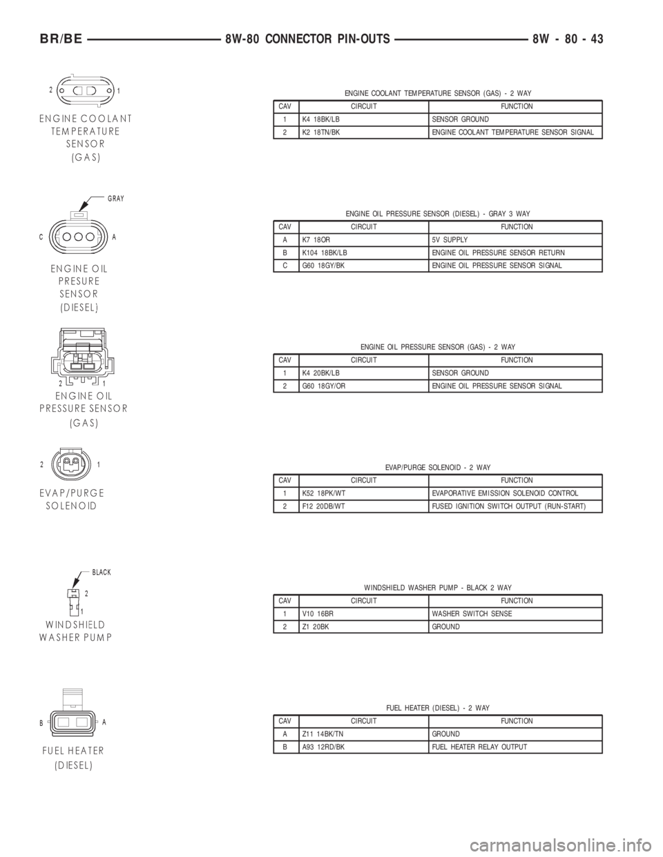
ENGINE COOLANT TEMPERATURE SENSOR (GAS)-2WAY
CAV CIRCUIT FUNCTION
1 K4 18BK/LB SENSOR GROUND
2 K2 18TN/BK ENGINE COOLANT TEMPERATURE SENSOR SIGNAL
ENGINE OIL PRESSURE SENSOR (DIESEL) - GRAY 3 WAY
CAV CIRCUIT FUNCTION
A K7 18OR 5V SUPPLY
B K104 18BK/LB ENGINE OIL PRESSURE SENSOR RETURN
C G60 18GY/BK ENGINE OIL PRESSURE SENSOR SIGNAL
ENGINE OIL PRESSURE SENSOR (GAS)-2WAY
CAV CIRCUIT FUNCTION
1 K4 20BK/LB SENSOR GROUND
2 G60 18GY/OR ENGINE OIL PRESSURE SENSOR SIGNAL
EVAP/PURGE SOLENOID-2WAY
CAV CIRCUIT FUNCTION
1 K52 18PK/WT EVAPORATIVE EMISSION SOLENOID CONTROL
2 F12 20DB/WT FUSED IGNITION SWITCH OUTPUT (RUN-START)
WINDSHIELD WASHER PUMP - BLACK 2 WAY
CAV CIRCUIT FUNCTION
1 V10 16BR WASHER SWITCH SENSE
2 Z1 20BK GROUND
FUEL HEATER (DIESEL)-2WAY
CAV CIRCUIT FUNCTION
A Z11 14BK/TN GROUND
B A93 12RD/BK FUEL HEATER RELAY OUTPUT
BR/BE8W-80 CONNECTOR PIN-OUTS 8W - 80 - 43
Page 1008 of 2255
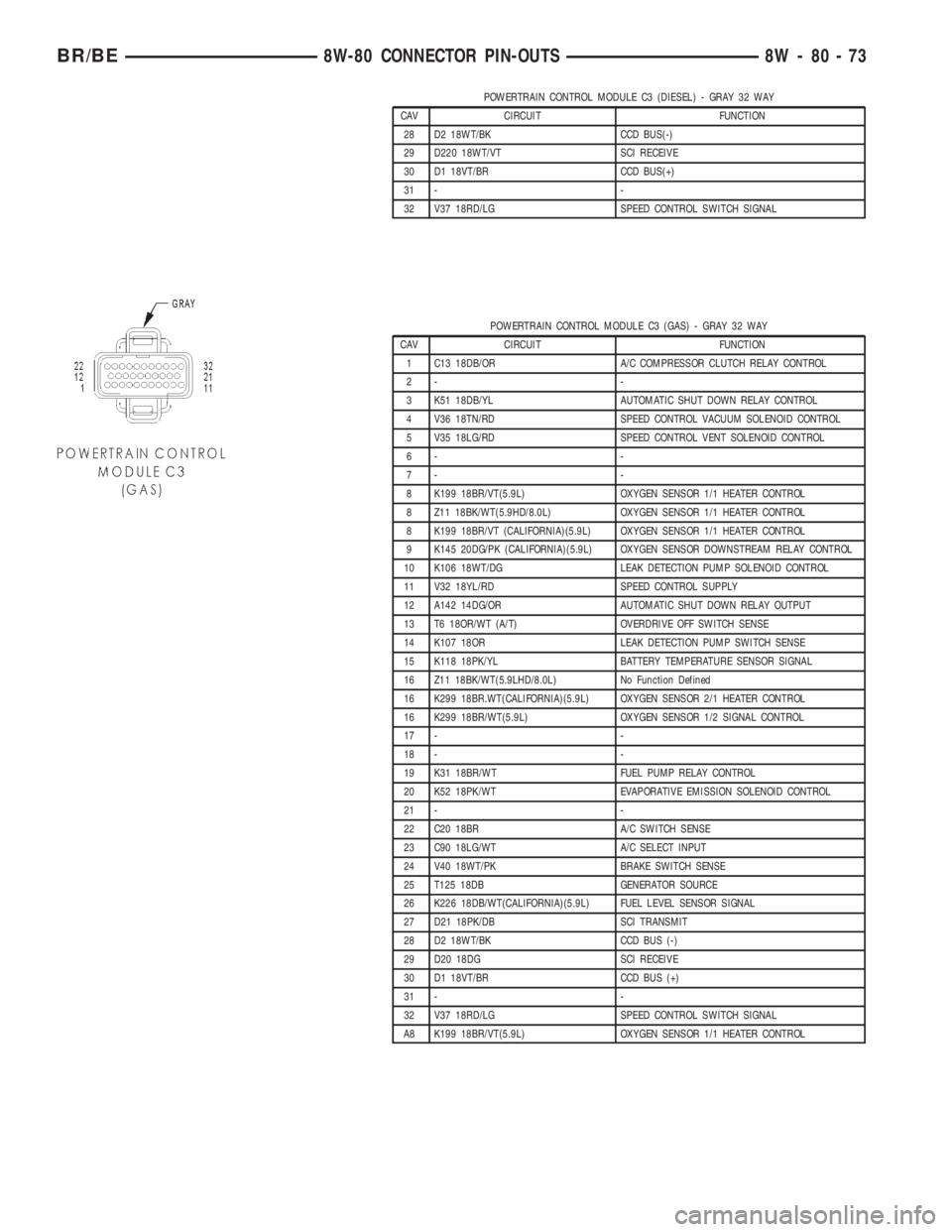
POWERTRAIN CONTROL MODULE C3 (DIESEL) - GRAY 32 WAY
CAV CIRCUIT FUNCTION
28 D2 18WT/BK CCD BUS(-)
29 D220 18WT/VT SCI RECEIVE
30 D1 18VT/BR CCD BUS(+)
31 - -
32 V37 18RD/LG SPEED CONTROL SWITCH SIGNAL
POWERTRAIN CONTROL MODULE C3 (GAS) - GRAY 32 WAY
CAV CIRCUIT FUNCTION
1 C13 18DB/OR A/C COMPRESSOR CLUTCH RELAY CONTROL
2- -
3 K51 18DB/YL AUTOMATIC SHUT DOWN RELAY CONTROL
4 V36 18TN/RD SPEED CONTROL VACUUM SOLENOID CONTROL
5 V35 18LG/RD SPEED CONTROL VENT SOLENOID CONTROL
6- -
7- -
8 K199 18BR/VT(5.9L) OXYGEN SENSOR 1/1 HEATER CONTROL
8 Z11 18BK/WT(5.9HD/8.0L) OXYGEN SENSOR 1/1 HEATER CONTROL
8 K199 18BR/VT (CALIFORNIA)(5.9L) OXYGEN SENSOR 1/1 HEATER CONTROL
9 K145 20DG/PK (CALIFORNIA)(5.9L) OXYGEN SENSOR DOWNSTREAM RELAY CONTROL
10 K106 18WT/DG LEAK DETECTION PUMP SOLENOID CONTROL
11 V32 18YL/RD SPEED CONTROL SUPPLY
12 A142 14DG/OR AUTOMATIC SHUT DOWN RELAY OUTPUT
13 T6 18OR/WT (A/T) OVERDRIVE OFF SWITCH SENSE
14 K107 18OR LEAK DETECTION PUMP SWITCH SENSE
15 K118 18PK/YL BATTERY TEMPERATURE SENSOR SIGNAL
16 Z11 18BK/WT(5.9LHD/8.0L) No Function Defined
16 K299 18BR.WT(CALIFORNIA)(5.9L) OXYGEN SENSOR 2/1 HEATER CONTROL
16 K299 18BR/WT(5.9L) OXYGEN SENSOR 1/2 SIGNAL CONTROL
17 - -
18 - -
19 K31 18BR/WT FUEL PUMP RELAY CONTROL
20 K52 18PK/WT EVAPORATIVE EMISSION SOLENOID CONTROL
21 - -
22 C20 18BR A/C SWITCH SENSE
23 C90 18LG/WT A/C SELECT INPUT
24 V40 18WT/PK BRAKE SWITCH SENSE
25 T125 18DB GENERATOR SOURCE
26 K226 18DB/WT(CALIFORNIA)(5.9L) FUEL LEVEL SENSOR SIGNAL
27 D21 18PK/DB SCI TRANSMIT
28 D2 18WT/BK CCD BUS (-)
29 D20 18DG SCI RECEIVE
30 D1 18VT/BR CCD BUS (+)
31 - -
32 V37 18RD/LG SPEED CONTROL SWITCH SIGNAL
A8 K199 18BR/VT(5.9L) OXYGEN SENSOR 1/1 HEATER CONTROL
BR/BE8W-80 CONNECTOR PIN-OUTS 8W - 80 - 73
Page 1083 of 2255
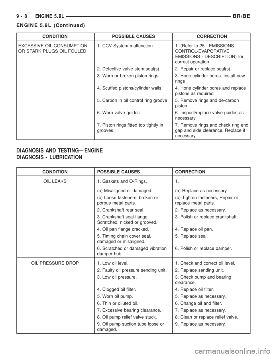
CONDITION POSSIBLE CAUSES CORRECTION
EXCESSIVE OIL CONSUMPTION
OR SPARK PLUGS OIL FOULED1. CCV System malfunction 1. (Refer to 25 - EMISSIONS
CONTROL/EVAPORATIVE
EMISSIONS - DESCRIPTION) for
correct operation
2. Defective valve stem seal(s) 2. Repair or replace seal(s)
3. Worn or broken piston rings 3. Hone cylinder bores. Install new
rings
4. Scuffed pistons/cylinder walls 4. Hone cylinder bores and replace
pistons as required
5. Carbon in oil control ring groove 5. Remove rings and de-carbon
piston
6. Worn valve guides 6. Inspect/replace valve guides as
necessary
7. Piston rings fitted too tightly in
grooves7. Remove rings and check ring end
gap and side clearance. Replace if
necessary
DIAGNOSIS AND TESTINGÐENGINE
DIAGNOSIS - LUBRICATION
CONDITION POSSIBLE CAUSES CORRECTION
OIL LEAKS 1. Gaskets and O-Rings. 1.
(a) Misaligned or damaged. (a) Replace as necessary.
(b) Loose fasteners, broken or
porous metal parts.(b) Tighten fasteners, Repair or
replace metal parts.
2. Crankshaft rear seal 2. Replace as necessary.
3. Crankshaft seal flange.
Scratched, nicked or grooved.3. Polish or replace crankshaft.
4. Oil pan flange cracked. 4. Replace oil pan.
5. Timing chain cover seal,
damaged or misaligned.5. Replace seal.
6. Scratched or damaged vibration
damper hub.6. Polish or replace damper.
OIL PRESSURE DROP 1. Low oil level. 1. Check and correct oil level.
2. Faulty oil pressure sending unit. 2. Replace sending unit.
3. Low oil pressure. 3. Check pump and bearing
clearance.
4. Clogged oil filter. 4. Replace oil filter.
5. Worn oil pump. 5. Replace as necessary.
6. Thin or diluted oil. 6. Change oil and filter.
7. Excessive bearing clearance. 7. Replace as necessary.
8. Oil pump relief valve stuck. 8. Clean or replace relief valve.
9. Oil pump suction tube loose or
damaged.9. Replace as necessary.
9 - 8 ENGINE 5.9LBR/BE
ENGINE 5.9L (Continued)