2002 DODGE RAM 8W wiring
[x] Cancel search: 8W wiringPage 323 of 2255

(1) Disconnect negative battery cable from battery.
(2) Partially drain cooling system (Refer to 7 -
COOLING - STANDARD PROCEDURE).Do not
waste reusable coolant. If the solution is clean, drain
the coolant into a clean container for reuse.
(3) Remove upper radiator hose clamp at radiator.
A special clamp tool must be used to remove the con-
stant tension clamps. Remove hose at radiator.
(4) Disconnect throttle cable from clip at radiator
fan shroud.
(5) Unplug wiring harness from A/C compressor.
(6) Remove the air cleaner assembly.
(7) Remove accessory drive belt (Refer to 7 -
COOLING/ACCESSORY DRIVE/DRIVE BELTS -
REMOVAL).
(8)5.9L V-8 LDC-Gas:The drive belt idler pulley
must be removed to gain access to one of the A/C
compressor/generator bracket mounting bolts.
Remove the idler pulley bolt and remove idler pulley
(Fig. 64).(9)5.9L HDC-Gas:The automatic belt tensioner/
pulley assembly must be removed to gain access to
one of the A/C compressor/generator bracket mount-
ing bolts. Remove the tensioner mounting bolt (Fig.
65) and remove tensioner.
(10) Remove the engine oil dipstick tube mounting
bolt at the side of the A/C-generator mounting
bracket.
(11) Disconnect throttle body control cables.
(12) Remove heater hose coolant return tube
mounting bolt (Fig. 66) (Fig. 67) and remove tube
from engine. Discard the old tube O-ring.
(13) Remove bracket-to-intake manifold bolts
(number 1 and 2 (Fig. 63).
(14) Remove remaining bracket-to-engine bolts
(Fig. 68) (Fig. 69).
Fig. 64 Idler Pulley - 5.9L V-8 LDC-Gas Engine
Fig. 65 Belt Tensioner - 5.9L HDC-Gas Engine
1 - PULLEY BOLT
2 - IDLER PULLEY
3 - TENSIONER PULLEY
4 - TENSIONER
5 - TENSIONER MOUNTING BOLT
7 - 74 ENGINEBR/BE
WATER PUMP INLET TUBE - 5.9L (Continued)
Page 326 of 2255
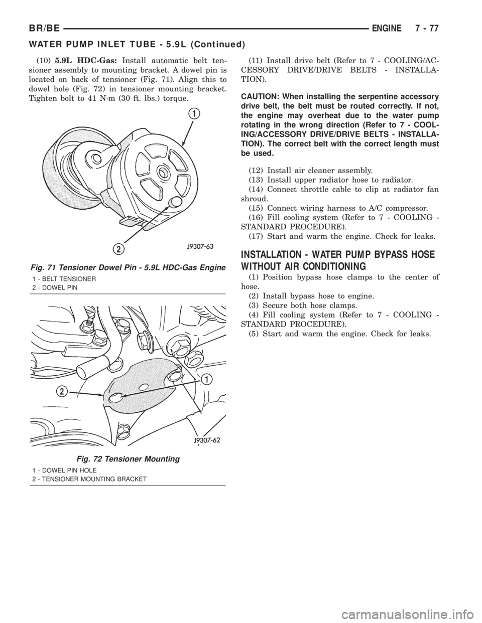
(10)5.9L HDC-Gas:Install automatic belt ten-
sioner assembly to mounting bracket. A dowel pin is
located on back of tensioner (Fig. 71). Align this to
dowel hole (Fig. 72) in tensioner mounting bracket.
Tighten bolt to 41 N´m (30 ft. lbs.) torque.(11) Install drive belt (Refer to 7 - COOLING/AC-
CESSORY DRIVE/DRIVE BELTS - INSTALLA-
TION).
CAUTION: When installing the serpentine accessory
drive belt, the belt must be routed correctly. If not,
the engine may overheat due to the water pump
rotating in the wrong direction (Refer to 7 - COOL-
ING/ACCESSORY DRIVE/DRIVE BELTS - INSTALLA-
TION). The correct belt with the correct length must
be used.
(12) Install air cleaner assembly.
(13) Install upper radiator hose to radiator.
(14) Connect throttle cable to clip at radiator fan
shroud.
(15) Connect wiring harness to A/C compressor.
(16) Fill cooling system (Refer to 7 - COOLING -
STANDARD PROCEDURE).
(17) Start and warm the engine. Check for leaks.
INSTALLATION - WATER PUMP BYPASS HOSE
WITHOUT AIR CONDITIONING
(1) Position bypass hose clamps to the center of
hose.
(2) Install bypass hose to engine.
(3) Secure both hose clamps.
(4) Fill cooling system (Refer to 7 - COOLING -
STANDARD PROCEDURE).
(5) Start and warm the engine. Check for leaks.
Fig. 71 Tensioner Dowel Pin - 5.9L HDC-Gas Engine
1 - BELT TENSIONER
2 - DOWEL PIN
Fig. 72 Tensioner Mounting
1 - DOWEL PIN HOLE
2 - TENSIONER MOUNTING BRACKET
BR/BEENGINE 7 - 77
WATER PUMP INLET TUBE - 5.9L (Continued)
Page 338 of 2255

AUDIO
TABLE OF CONTENTS
page page
AUDIO
DESCRIPTION..........................1
OPERATION............................2
DIAGNOSIS AND TESTING - AUDIO..........2
SPECIAL TOOLS
AUDIO SYSTEMS......................4
ANTENNA BODY & CABLE
DESCRIPTION..........................4
OPERATION............................4
DIAGNOSIS AND TESTING - ANTENNA.......5
REMOVAL.............................6
INSTALLATION..........................6
RADIO CHOKE RELAY
DESCRIPTION..........................7
OPERATION............................8
DIAGNOSIS AND TESTING - RADIO CHOKE
RELAY...............................8
REMOVAL.............................8
INSTALLATION..........................9
INSTRUMENT PANEL ANTENNA CABLE
REMOVAL.............................9
INSTALLATION..........................9
RADIO
DESCRIPTION.........................10
OPERATION...........................10
DIAGNOSIS AND TESTING - RADIO.........10
REMOVAL.............................11
INSTALLATION.........................11
RADIO NOISE SUPPRESSION COMPONENTS
DESCRIPTION.........................12
DIAGNOSIS AND TESTING - RADIO NOISE
SUPPRESSION COMPONENTS...........12ENGINE-TO-BODY GROUND STRAP
REMOVAL.............................12
INSTALLATION.........................13
CAB-TO- BED GROUND STRAP
REMOVAL.............................13
INSTALLATION.........................14
HEATER CORE GROUND STRAP
REMOVAL.............................14
INSTALLATION.........................14
REMOTE SWITCHES
DESCRIPTION.........................14
OPERATION...........................15
DIAGNOSIS AND TESTING - REMOTE
SWITCHES..........................15
REMOVAL.............................16
INSTALLATION.........................16
SPEAKER
DESCRIPTION.........................17
OPERATION...........................17
DIAGNOSIS AND TESTING - SPEAKER......17
A-PILLAR TWEETER SPEAKER
REMOVAL.............................18
INSTALLATION.........................19
FRONT DOOR SPEAKER
REMOVAL.............................19
INSTALLATION.........................19
REAR CAB SIDE PANEL SPEAKER
REMOVAL.............................20
INSTALLATION.........................20
REAR DOOR SPEAKER
REMOVAL.............................20
INSTALLATION.........................21
AUDIO
DESCRIPTION
An audio system is standard factory-installed
equipment on this model, unless the vehicle is
ordered with an available radio delete option. The
standard equipment audio system includes an
AM/FM/cassette (RAS sales code) receiver, and
speakers in four locations. Several combinations of
radio receivers and speaker systems are offered as
optional equipment on this model. The audio system
uses an ignition switched source of battery current so
that the system will only operate when the ignition
switch is in the On or Accessory positions. The audio
system includes the following components:²Antenna
²Clockspring (with remote radio switches only)
²Filter, choke and speaker relay (with premium
speaker system only)
²High-line or premium Central Timer Module
(CTM) (with remote radio switches)
²Radio noise suppression components
²Radio receiver
²Remote radio switches (optional with RAZ radio
receiver only)
²Speakers
Refer to Electrical, Restraints for more information
on the clockspring. Refer to Electrical, Body Control/
Central Control Module for more information on the
Central Timer Module. Refer to the appropriate wir-
ing information. The wiring information includes wir-
BR/BEAUDIO 8A - 1
Page 339 of 2255

ing diagrams, proper wire and connector repair
procedures, details of wire harness routing and
retention, connector pin-out information and location
views for the various wire harness connectors, splices
and grounds. Following are general descriptions of
the remaining major components in the standard and
optional factory-installed audio systems.
OPERATION
See the owner's manual in the vehicle glove box for
more information on the features, use and operation
of each of the available audio systems.
CENTRAL TIMER MODULE
The high-line or premium Central Timer Module
(CTM) can also control some features of the audio
system when the vehicle is equipped with the
optional RAZ radio receiver and remote radio
switches. A high-line CTM is used on high-line ver-
sions of this vehicle. A premium CTM is used on
vehicles equipped with the optional heated seats. The
CTM combines the functions of a chime/buzzer mod-
ule, an intermittent wipe module, an illuminated
entry module, a remote keyless entry module, and a
vehicle theft security system module in a single unit.
The high-line or premium CTM also controls and
integrates many of the additional electronic functions
and features included on models with this option.
The RAZ radio receiver with a remote radio switch
option is one of the features that the CTM controls.
The CTM is programmed to send switch status mes-sages over the Chrysler Collision Detection (CCD)
data bus to control the volume, seek, and pre-set sta-
tion advance functions of the RAZ radio receiver. The
CTM monitors the status of the remote radio
switches located on the steering wheel through a
hard wired circuit. The CTM then sends the proper
switch status messages to the radio receiver. The
electronic circuitry within the radio receiver responds
to the switch status messages it receives by adjusting
the radio settings as requested.
Refer to Electrical, Body Control/Central Timer
Module for more information on the high-line CTM.
Refer to Remote Radio Switch in Description and
Operation for more information on this component.
In addition, radio receivers connected to the CCD
data bus have several audio system functions that
can be diagnosed using a DRBIIItscan tool. Refer to
the proper Diagnostic Procedures manual for more
information on DRBIIIttesting of the audio systems.
DIAGNOSIS AND TESTING - AUDIO
WARNING: ON VEHICLES EQUIPPED WITH AIR-
BAGS, REFER TO ELECTRICAL, RESTRAINTS
BEFORE ATTEMPTING ANY STEERING WHEEL,
STEERING COLUMN, OR INSTRUMENT PANEL
COMPONENT DIAGNOSIS OR SERVICE. FAILURE
TO TAKE THE PROPER PRECAUTIONS COULD
RESULT IN ACCIDENTAL AIRBAG DEPLOYMENT
AND POSSIBLE PERSONAL INJURY.
Audio System Diagnosis
CONDITION POSSIBLE CAUSE CORRECTION
NO AUDIO 1. Fuse faulty. 1. Check radio fuses in junction block. Replace faulty
fuses, if required.
2. Radio connector faulty. 2. Check for loose or corroded radio connections. Repair,
if required.
3. Wiring faulty. 3. Check for battery voltage at radio connector. Repair
wiring, if required.
4. Ground faulty. 4. Check for continuity between radio chassis and a
known good ground. There should be continuity. Repair
ground, if required.
5. Radio faulty. 5. Refer to Radio in the Diagnosis and Testing section of
this group.
6. Speakers faulty. 6. Refer to Speaker in the Diagnosis and Testing section
of this group.
7. Amplifier faulty (if
equipped).7. Refer to Speaker in the Diagnosis and Testing section
of this group.
8A - 2 AUDIOBR/BE
AUDIO (Continued)
Page 340 of 2255

Audio System Diagnosis
CONDITION POSSIBLE CAUSE CORRECTION
NO DISPLAY 1. Fuse faulty. 1. Check radio fuses in junction block. Replace faulty
fuses, if required.
2. Radio connector faulty. 2. Check for loose or corroded radio connections. Repair,
if required.
3. Wiring faulty. 3. Check for battery voltage at radio connector. Repair
wiring, if required.
4. Ground faulty. 4. Check for continuity between radio chassis and a
known good ground. There should be continuity. Repair
ground, if required.
5. Radio faulty. 5. Refer to Radio in the Diagnosis and Testing section of
this group.
CLOCK WILL NOT KEEP
SET TIME1. Fuse faulty. 1. Check ignition-off draw fuse. Replace faulty fuse, if
required.
2. Radio connector faulty. 2. Check for loose or corroded radio connections. Repair,
if required.
3. Wiring faulty. 3. Check for battery voltage at radio connector. Repair
wiring, if required.
4. Ground faulty. 4. Check for continuity between radio chassis and a
known good ground. There should be continuity. Repair
ground, if required.
5. Radio faulty. 5. Refer to Radio in the Diagnosis and Testing section of
this group.
POOR RADIO
RECEPTION1. Antenna faulty. 1. Refer to Antenna in the Diagnosis and Testing section
of this group.
2. Ground faulty. 2. Check for continuity between radio chassis and a
known good ground. There should be continuity. Repair
ground, if required.
3. Radio faulty. 3. Refer to Radio in the Diagnosis and Testing section of
this group.
4. Faulty EMI or RFI
noise suppression.4. Refer to Radio Frequency Interference in the Diagnosis
and Testing section of this group.
NO/POOR TAPE
OPERATION1. Faulty tape. 1. Insert known good tape and test operation.
2. Foreign objects behind
tape door.2. Remove foreign objects and test operation.
3. Dirty cassette tape
head.3. Clean head with Mopar Cassette Head Cleaner.
4. Faulty tape deck. 4. Exchange or replace radio, if required.
NO COMPACT DISC
OPERATION1. Faulty CD. 1. Insert known good CD and test operation.
2. Foreign material on
CD.2. Clean CD and test operation.
3. Condensation on CD
or optics.3. Allow temperature of vehicle interior to stabilize and
test operation.
4. Faulty CD player. 4. Exchange or replace radio, if required.
BR/BEAUDIO 8A - 3
AUDIO (Continued)
Page 345 of 2255

OPERATION
The filter, choke, and speaker relay unit is used to
control the supply of fused battery current to the
front door speaker-mounted dual amplifiers. The
speaker relay is energized by a fused 12 volt output
from the radio receiver whenever the radio is turned
on. For complete circuit diagrams, refer to the appro-
priate wiring information. The wiring information
includes wiring diagrams, proper wire and connector
repair procedures, details of wire harness routing
and retention, connector pin-out information and
location views for the various wire harness connec-
tors, splices and grounds.
DIAGNOSIS AND TESTING - RADIO CHOKE
RELAY
The filter, choke and speaker relay is used to
switch power to the individual speaker amplifiers
used with the Infinity premium speaker package.
The choke and relay are serviced only as a unit. If all
of the speakers are inoperative the filter, choke and
speaker relay unit should be considered suspect.
However, before replacement make the following
checks of the filter, choke and speaker relay circuits.
For complete circuit diagrams, refer to the appropri-
ate wiring information. The wiring information
includes wiring diagrams, proper wire and connector
repair procedures, details of wire harness routing
and retention, connector pin-out information and
location views for the various wire harness connec-
tors, splices and grounds.
(1) Check the fused B(+) fuse in the junction block.
If OK, go to Step 2. If not OK, replace the faulty
fuse.
(2) Check for battery voltage at the fused B(+) fuse
in the junction block. If OK, go to Step 3. If not OK,
repair the open fused B(+) circuit to the battery as
required.
(3) Disconnect the instrument panel wire harness
connector from the filter, choke and speaker relay
unit. Check for battery voltage at the fused B(+) cir-
cuit cavity of the instrument panel wire harness con-
nector for the filter, choke and speaker relay unit. If
OK, go to Step 4. If not OK, repair the open fused
B(+) circuit to the junction block fuse as required.
(4) Probe the ground circuit cavity of the instru-
ment panel wire harness connector for the filter,
choke and speaker relay unit. Check for continuity to
a good ground. There should be continuity. If OK, go
to Step 5. If not OK, repair the open ground circuit to
ground as required.
(5) Turn the ignition switch to the On position and
turn the radio on. Check for battery voltage at the
radio 12-volt output circuit cavity of the instrument
panel wire harness connector for the filter, choke and
speaker relay unit. If OK, go to Step 6. If not OK,repair the open radio 12-volt output circuit to the
radio as required.
(6) Turn the radio and ignition switches to the Off
position. Reconnect the instrument panel wire har-
ness connector to the filter, choke and speaker relay
unit. Check for battery voltage at the amplified
speaker (+) circuit cavity of the instrument panel
wire harness connector for the filter, choke and
speaker relay unit. There should be zero volts. Turn
the ignition and radio switches to the On position.
There should now be battery voltage. If OK, repair
the open amplified speaker (+) circuits to the speak-
er-mounted amplifiers as required. If not OK, replace
the faulty filter, choke and speaker relay unit.
REMOVAL
(1) Disconnect and isolate the battery negative
cable.
(2) Reach under the driver side of the instrument
panel near the 16-way data link connector and
inboard of the ash receiver to access the filter, choke,
and speaker relay (Fig. 6) .
(3) Disconnect the instrument panel wire harness
connector from the filter, choke and speaker relay
wire harness connector.
Fig. 6 Filter, Choke, and Speaker Relay Remove/
Install
1 - ASH RECEIVER HOUSING
2 - DATA LINK CONNECTOR
3 - CENTER BRACE
4 - SCREW
5 - CHOKE AND RELAY
6 - WIRE HARNESS CONNECTORS
8A - 8 AUDIOBR/BE
RADIO CHOKE RELAY (Continued)
Page 347 of 2255
RADIO
DESCRIPTION
Available factory-installed radio receivers for this
model include an AM/FM/cassette (RAS sales code),
an AM/FM/CD/3-band graphic equalizer (RBR sales
code), or an AM/FM/CD/cassette/3-band graphic
equalizer (RAZ sales code). The factory-installed RAZ
sales code radio receivers can also communicate on
the Chrysler Collision Detection (CCD) data bus net-
work through a separate two-way wire harness con-
nector. All factory-installed receivers are stereo
Electronically Tuned Radios (ETR) and include an
electronic digital clock function.
These radio receivers can only be serviced by an
authorized radio repair station. See the latest War-
ranty Policies and Procedures manual for a current
listing of authorized radio repair stations.
All vehicles are equipped with an Ignition-Off
Draw (IOD) fuse that is removed when the vehicle is
shipped from the factory. This fuse feeds various
accessories that require battery current when the
ignition switch is in the Off position, including the
clock. The IOD fuse is removed to prevent battery
discharge during vehicle storage.
When removing or installing the IOD fuse, it is
important that the ignition switch be in the Off posi-
tion. Failure to place the ignition switch in the Off
position can cause the radio display to become scram-
bled when the IOD fuse is removed and replaced.
Removing and replacing the IOD fuse again, with the
ignition switch in the Off position, will correct the
scrambled display condition.
The IOD fuse should be checked if the radio or
clock displays are inoperative. The IOD fuse is
located in the junction block. Refer to the fuse layout
label on the back of the instrument panel fuse access
panel for IOD fuse identification and location.
OPERATION
The radio receiver operates on fused battery cur-
rent that is available only when the ignition switch is
in the On or Accessory positions. The electronic digi-
tal clock function of the radio operates on fused bat-
tery current supplied through the IOD fuse,
regardless of the ignition switch position.
For more information on the features, setting pro-
cedures, and control functions for each of the avail-
able factory-installed radio receivers, see the owner's
manual in the vehicle glove box. For complete circuit
diagrams, refer to the appropriate wiring informa-
tion. The wiring information includes wiring dia-
grams, proper wire and connector repair procedures,
details of wire harness routing and retention, connec-
tor pin-out information and location views for the
various wire harness connectors, splices and grounds.
DIAGNOSIS AND TESTING - RADIO
If the vehicle is equipped with the optional remote
radio switches located on the steering wheel and the
problem being diagnosed is related to one of the
symptoms listed below, be certain to check the
remote radio switches and circuits. Refer to Audio,
Remote Radio Switch prior to attempting radio diag-
nosis or repair.
²Stations changing with no remote radio switch
input
²Radio memory presets not working properly
²Volume changes with no remote radio switch
input
²Remote radio switch buttons taking on other
functions
²CD player skipping tracks
²Remote radio switch inoperative.
For complete circuit diagrams, refer to the appro-
priate wiring information. The wiring information
includes wiring diagrams, proper wire and connector
repair procedures, details of wire harness routing
and retention, connector pin-out information and
location views for the various wire harness connec-
tors, splices and grounds.
WARNING: ON VEHICLES EQUIPPED WITH AIR-
BAGS, REFER TO ELECTRICAL, RESTRAINTS
BEFORE ATTEMPTING ANY STEERING WHEEL,
STEERING COLUMN, OR INSTRUMENT PANEL
COMPONENT DIAGNOSIS OR SERVICE. FAILURE
TO TAKE THE PROPER PRECAUTIONS COULD
RESULT IN ACCIDENTAL AIRBAG DEPLOYMENT
AND POSSIBLE PERSONAL INJURY.
CAUTION: The speaker output of the radio receiver
is a ªfloating groundº system. Do not allow any
speaker lead to short to ground, as damage to the
radio receiver may result.
(1) Check the fused B(+) fuse in the junction block.
If OK, go to Step 2. If not OK, repair the shorted cir-
cuit or component as required and replace the faulty
fuse.
(2) Check for battery voltage at the fused B(+) fuse
in the junction block. If OK, go to Step 3. If not OK,
repair the open fused B(+) circuit to the Power Dis-
tribution Center (PDC) as required.
(3) Check the fused ignition switch output (acc/
run) fuse in the junction block. If OK, go to Step 4. If
not OK, repair the shorted circuit or component as
required and replace the faulty fuse(s).
(4) Turn the ignition switch to the On position.
Check for battery voltage at the fused ignition switch
output (acc/run) fuse in the junction block. If OK, go
to Step 5. If not OK, repair the open fused ignition
8A - 10 AUDIOBR/BE
Page 348 of 2255

switch output (acc/run) circuit to the ignition switch
as required.
(5) Turn the ignition switch to the Off position.
Disconnect and isolate the battery negative cable.
Remove the radio receiver from the instrument
panel, but do not disconnect the wire harness connec-
tors. Check for continuity between the radio receiver
chassis and a good ground. There should be continu-
ity. If OK, go to Step 6. If not OK, repair the open
ground circuit to ground as required.
(6) Connect the battery negative cable. Turn the
ignition switch to the On position. Check for battery
voltage at the fused ignition switch output (acc/run)
circuit cavity of the left (gray) radio wire harness
connector. If OK, go to Step 7. If not OK, repair the
open fused ignition switch output (acc/run) circuit to
the junction block fuse as required.
(7) Turn the ignition switch to the Off position.
Check for battery voltage at the fused B(+) circuit
cavity of the left (gray) radio wire harness connector.
If OK, replace the faulty radio receiver. If not OK,
repair the open fused B(+) circuit to the junction
block fuse as required.
REMOVAL
(1) Disconnect and isolate the battery negative
cable.
(2) Remove the cluster bezel from the instrument
panel.
(3) Remove the two screws that secure the radio
receiver to the instrument panel (Fig. 8).
(4) Pull the radio receiver out from the instrument
panel far enough to access the instrument panel wire
harness connectors and the antenna coaxial cable
connector (Fig. 9).
(5) Disconnect the instrument panel wire harness
connectors and the antenna coaxial cable connector
from the receptacles on the rear of the radio receiver.
(6) If so equipped, remove the screw that secures
the ground wire to the back of the radio receiver
chassis.
(7) Remove the radio receiver from the instrument
panel.
INSTALLATION
(1) Position the radio receiver to the instrument
panel.
(2) If so equipped, install and tighten the screw
that secures the ground wire to the back of the radio
receiver chassis. Tighten the screw to 7 N´m (65 in.
lbs.).
(3) Reconnect the instrument panel wire harness
connectors and the antenna coaxial cable connector
to the receptacles on the rear of the radio receiver.
(4) Position the radio receiver into the mounting
hole in the instrument panel.(5) Install and tighten the two screws that secure
the radio receiver to the instrument panel. Tighten
the screws to 5 N´m (45 in. lbs.).
(6) Install the cluster bezel onto the instrument
panel.
(7) Reconnect the battery negative cable.
Fig. 8 Radio Receiver Remove/Install
1 - WIRE HARNESS CONNECTORS
2 - ANTENNA COAXIAL CABLE
3 - RADIO
4 - SCREW
5 - GROUND WIRE
6 - SCREW
Fig. 9 Radio Receiver Connections - Typical
1 - ANTENNA CABLE
2 - RADIO
3 - INSTRUMENT PANEL WIRING
4 - GROUND WIRE
BR/BEAUDIO 8A - 11
RADIO (Continued)