2002 DODGE RAM oil pressure
[x] Cancel search: oil pressurePage 259 of 2255

CONDITION POSSIBLE CAUSES CORRECTION
TEMPERATURE GAUGE READING
IS INCONSISTENT (FLUCTUATES,
CYCLES OR IS ERRATIC)1. During cold weather operation,
with the heater blower in the high
position, the gauge reading may
drop slightly.1. A normal condition. No correction
is necessary.
2. Temperature gauge or engine
mounted gauge sensor defective or
shorted. Also, corroded or loose
wiring in this circuit.2. Check operation of gauge and
repair if necessary. (Refer to 8 -
ELECTRICAL/INSTRUMENT
CLUSTER - DIAGNOSIS AND
TESTING).
3. Gauge reading rises when
vehicle is brought to a stop after
heavy use (engine still running)3. A normal condition. No correction
is necessary. Gauge should return
to normal range after vehicle is
driven.
4. Gauge reading high after
re-starting a warmed up (hot)
engine.4. A normal condition. No correction
is necessary. The gauge should
return to normal range after a few
minutes of engine operation.
5. Coolant level low in radiator (air
will build up in the cooling system
causing the thermostat to open
late).5. Check and correct coolant leaks.
(Refer to 7 - COOLING -
DIAGNOSIS AND TESTING).
6. Cylinder head gasket leaking
allowing exhaust gas to enter
cooling system causing a
thermostat to open late.6. (a) Check for cylinder head
gasket leaks. (Refer to 7 -
COOLING - DIAGNOSIS AND
TESTING).
(b) Check for coolant in the engine
oil. Inspect for white steam emitting
from the exhaust system. Repair as
necessary.
7. Water pump impeller loose on
shaft.7. Check water pump and replace
as necessary. (Refer to 7 -
COOLING/ENGINE/WATER PUMP -
REMOVAL).
8. Loose accessory drive belt.
(water pump slipping)8. (Refer to 7 - COOLING/
ACCESSORY DRIVE/DRIVE BELTS
- DIAGNOSIS AND TESTING).
Check and correct as necessary.
9. Air leak on the suction side of
the water pump allows air to build
up in cooling system causing
thermostat to open late.9. Locate leak and repair as
necessary.
PRESSURE CAP IS BLOWING
OFF STEAM AND/OR COOLANT
TO COOLANT TANK.
TEMPERATURE GAUGE READING
MAY BE ABOVE NORMAL BUT
NOT HIGH. COOLANT LEVEL MAY
BE HIGH IN COOLANT RESERVE/
OVERFLOW TANK1. Pressure relief valve in radiator
cap is defective.1. Check condition of radiator cap
and cap seals. (Refer to 7 -
COOLING/ENGINE/RADIATOR
PRESSURE CAP - DIAGNOSIS
AND TESTING). Replace cap as
necessary.
7 - 10 COOLINGBR/BE
COOLING (Continued)
Page 268 of 2255

ACCESSORY DRIVE
TABLE OF CONTENTS
page page
BELT TENSIONERS - 5.9L
DESCRIPTION.........................19
OPERATION...........................19
REMOVAL.............................19
INSTALLATION.........................20
BELT TENSIONERS - 8.0L
DESCRIPTION.........................20
OPERATION...........................21
REMOVAL.............................21
INSTALLATION.........................22
BELT TENSIONERS - 5.9L DIESEL
DESCRIPTION.........................23
OPERATION...........................23
REMOVAL.............................23
INSTALLATION.........................23
DRIVE BELTS - 5.9L
DIAGNOSIS AND TESTING - ACCESSORY
DRIVE BELT.........................24
REMOVAL.............................26INSTALLATION.........................26
DRIVE BELTS - 8.0L
DIAGNOSIS AND TESTINGÐACCESSORY
DRIVE BELT.........................27
REMOVAL.............................29
INSTALLATION.........................29
DRIVE BELTS - 5.9L DIESEL
DIAGNOSIS AND TESTINGÐACCESSORY
DRIVE BELT.........................30
REMOVAL.............................32
INSTALLATION.........................32
VACUUM PUMP - 5.9L DIESEL
DESCRIPTION.........................33
OPERATION...........................34
DIAGNOSIS AND TESTINGÐVACUUM PUMP
OUTPUT............................34
REMOVAL.............................34
INSTALLATION.........................36
BELT TENSIONERS - 5.9L
DESCRIPTION
Correct drive belt tension is required to ensure
optimum performance of the belt driven engine acces-
sories. If specified tension is not maintained, belt
slippage may cause; engine overheating, lack of
power steering assist, loss of air conditioning capac-
ity, reduced generator output rate, and greatly
reduced belt life.
It is not necessary to adjust belt tension on the
5.9L engines. These engines are equipped with an
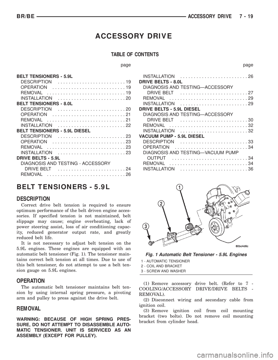
automatic belt tensioner (Fig. 1). The tensioner main-
tains correct belt tension at all times. Due to use of
this belt tensioner, do not attempt to use a belt ten-
sion gauge on 5.9L engines.
OPERATION
The automatic belt tensioner maintains belt ten-
sion by using internal spring pressure, a pivoting
arm and pulley to press against the drive belt.
REMOVAL
WARNING: BECAUSE OF HIGH SPRING PRES-
SURE, DO NOT ATTEMPT TO DISASSEMBLE AUTO-
MATIC TENSIONER. UNIT IS SERVICED AS AN
ASSEMBLY (EXCEPT FOR PULLEY).(1) Remove accessory drive belt. (Refer to 7 -
COOLING/ACCESSORY DRIVE/DRIVE BELTS -
REMOVAL).
(2) Disconnect wiring and secondary cable from
ignition coil.
(3) Remove ignition coil from coil mounting
bracket (two bolts). Do not remove coil mounting
bracket from cylinder head.
Fig. 1 Automatic Belt Tensioner - 5.9L Engines
1 - AUTOMATIC TENSIONER
2 - COIL AND BRACKET
3 - SCREW AND WASHER
BR/BEACCESSORY DRIVE 7 - 19
Page 270 of 2255

OPERATION
WARNING: THE AUTOMATIC BELT TENSIONER
ASSEMBLY IS SPRING LOADED. DO NOT ATTEMPT
TO DISASSEMBLE THE TENSIONER ASSEMBLY.
The automatic belt tensioner maintains correct belt
tension using a coiled spring within the tensioner
housing. The spring applies pressure to the tensioner
arm pressing the arm into the belt, tensioning the
belt.
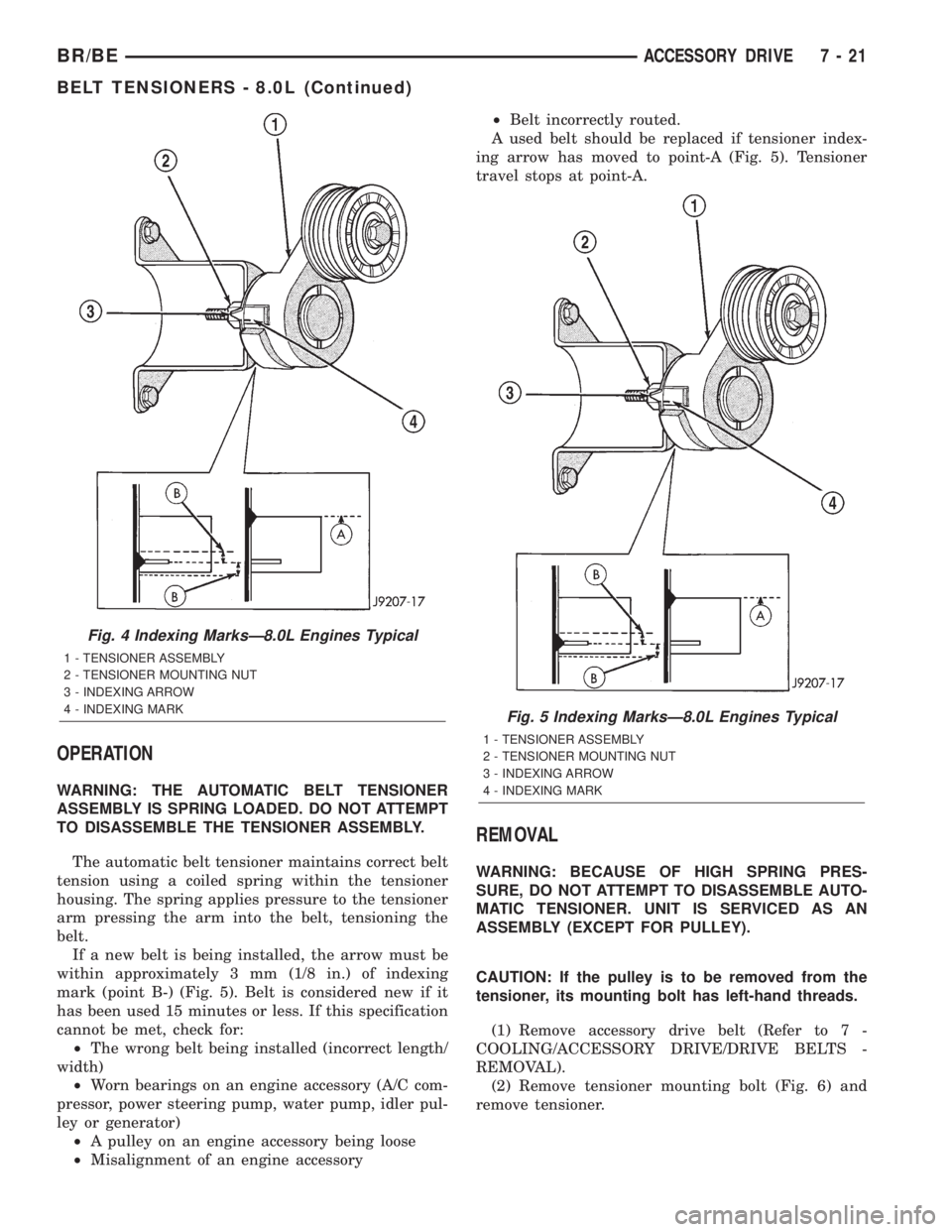
If a new belt is being installed, the arrow must be
within approximately 3 mm (1/8 in.) of indexing
mark (point B-) (Fig. 5). Belt is considered new if it
has been used 15 minutes or less. If this specification
cannot be met, check for:
²The wrong belt being installed (incorrect length/
width)
²Worn bearings on an engine accessory (A/C com-
pressor, power steering pump, water pump, idler pul-
ley or generator)
²A pulley on an engine accessory being loose
²Misalignment of an engine accessory²Belt incorrectly routed.
A used belt should be replaced if tensioner index-
ing arrow has moved to point-A (Fig. 5). Tensioner
travel stops at point-A.
REMOVAL
WARNING: BECAUSE OF HIGH SPRING PRES-
SURE, DO NOT ATTEMPT TO DISASSEMBLE AUTO-
MATIC TENSIONER. UNIT IS SERVICED AS AN
ASSEMBLY (EXCEPT FOR PULLEY).
CAUTION: If the pulley is to be removed from the
tensioner, its mounting bolt has left-hand threads.
(1) Remove accessory drive belt (Refer to 7 -
COOLING/ACCESSORY DRIVE/DRIVE BELTS -
REMOVAL).
(2) Remove tensioner mounting bolt (Fig. 6) and
remove tensioner.
Fig. 4 Indexing MarksÐ8.0L Engines Typical
1 - TENSIONER ASSEMBLY
2 - TENSIONER MOUNTING NUT
3 - INDEXING ARROW
4 - INDEXING MARK
Fig. 5 Indexing MarksÐ8.0L Engines Typical
1 - TENSIONER ASSEMBLY
2 - TENSIONER MOUNTING NUT
3 - INDEXING ARROW
4 - INDEXING MARK
BR/BEACCESSORY DRIVE 7 - 21
BELT TENSIONERS - 8.0L (Continued)
Page 272 of 2255

BELT TENSIONERS - 5.9L
DIESEL
DESCRIPTION
Drive belts on all engines are equipped with a
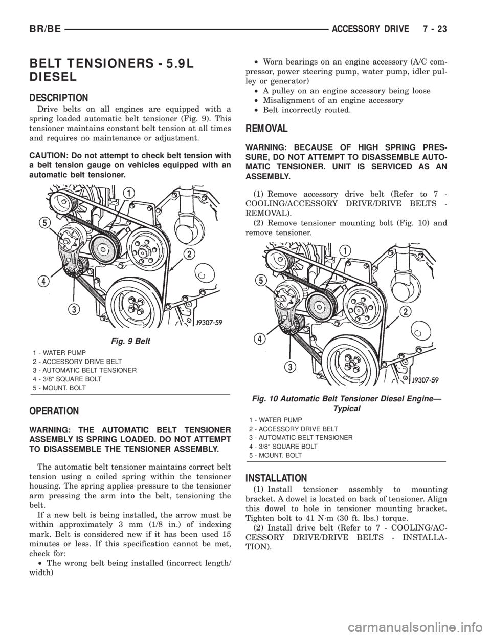
spring loaded automatic belt tensioner (Fig. 9). This
tensioner maintains constant belt tension at all times
and requires no maintenance or adjustment.
CAUTION: Do not attempt to check belt tension with
a belt tension gauge on vehicles equipped with an
automatic belt tensioner.
OPERATION
WARNING: THE AUTOMATIC BELT TENSIONER
ASSEMBLY IS SPRING LOADED. DO NOT ATTEMPT
TO DISASSEMBLE THE TENSIONER ASSEMBLY.
The automatic belt tensioner maintains correct belt
tension using a coiled spring within the tensioner
housing. The spring applies pressure to the tensioner
arm pressing the arm into the belt, tensioning the
belt.
If a new belt is being installed, the arrow must be
within approximately 3 mm (1/8 in.) of indexing
mark. Belt is considered new if it has been used 15
minutes or less. If this specification cannot be met,
check for:
²The wrong belt being installed (incorrect length/
width)²Worn bearings on an engine accessory (A/C com-
pressor, power steering pump, water pump, idler pul-
ley or generator)
²A pulley on an engine accessory being loose
²Misalignment of an engine accessory
²Belt incorrectly routed.
REMOVAL
WARNING: BECAUSE OF HIGH SPRING PRES-
SURE, DO NOT ATTEMPT TO DISASSEMBLE AUTO-
MATIC TENSIONER. UNIT IS SERVICED AS AN
ASSEMBLY.
(1) Remove accessory drive belt (Refer to 7 -
COOLING/ACCESSORY DRIVE/DRIVE BELTS -
REMOVAL).
(2) Remove tensioner mounting bolt (Fig. 10) and
remove tensioner.
INSTALLATION
(1) Install tensioner assembly to mounting
bracket. A dowel is located on back of tensioner. Align
this dowel to hole in tensioner mounting bracket.
Tighten bolt to 41 N´m (30 ft. lbs.) torque.
(2) Install drive belt (Refer to 7 - COOLING/AC-
CESSORY DRIVE/DRIVE BELTS - INSTALLA-
TION).
Fig. 9 Belt
1 - WATER PUMP
2 - ACCESSORY DRIVE BELT
3 - AUTOMATIC BELT TENSIONER
4 - 3/89SQUARE BOLT
5 - MOUNT. BOLT
Fig. 10 Automatic Belt Tensioner Diesel EngineÐ
Typical
1 - WATER PUMP
2 - ACCESSORY DRIVE BELT
3 - AUTOMATIC BELT TENSIONER
4 - 3/89SQUARE BOLT
5 - MOUNT. BOLT
BR/BEACCESSORY DRIVE 7 - 23
Page 286 of 2255

(6) Working from under vehicle, install pump
assembly lower attaching bolt. Then tighten upper
and lower bolt to 77 N´m (57 ft. lbs.).
(7) Position bracket on steering pump inboard
stud. Then install remaining adapter attaching nut
on stud. Tighten nut to 24 N´m (18 ft. lbs.).
(8) Connect oil feed line to vacuum pump connec-
tor and tighten line fitting.
(9) Connect steering pump pressure and return
lines to pump. Tighten pressure line fitting to 30
N´m (22 ft. lbs.).
(10) Connect vacuum hose to vacuum pump.
(11) Connect battery cables, if removed.
(12) Fill power steering pump reservoir and Purge
air from steering pump lines (Refer to 19 - STEER-
ING/PUMP - STANDARD PROCEDURE).
Fig. 30 Installing Pump Assembly On Engine
1 - PUMP ASSEMBLY
2 - PUMP GASKET
3 - DRIVE GEAR
BR/BEACCESSORY DRIVE 7 - 37
VACUUM PUMP - 5.9L DIESEL (Continued)
Page 288 of 2255

INSTALLATION.........................64
RADIATOR PRESSURE CAP
DESCRIPTION.........................64
OPERATION...........................64
DIAGNOSIS AND TESTING
DIAGNOSIS AND TESTINGÐRADIATOR
CAP-TO-FILLER NECK SEAL.............65
DIAGNOSIS AND TESTINGÐRADIATOR
CAP................................65
CLEANING............................65
INSPECTION..........................66
WATER PUMP - 5.9L
DESCRIPTION.........................66
OPERATION...........................66
DIAGNOSIS AND TESTINGÐWATER PUMP . . . 66
REMOVAL.............................66
CLEANING............................68
INSPECTION..........................68
INSTALLATION.........................68
WATER PUMP - 8.0L
DIAGNOSIS AND TESTINGÐWATER PUMP . . . 69
REMOVAL.............................69CLEANING............................71
INSPECTION..........................71
INSTALLATION.........................71
WATER PUMP - 5.9L DIESEL
DESCRIPTION.........................72
OPERATION...........................72
DIAGNOSIS AND TESTINGÐWATER PUMP . . . 72
REMOVAL.............................72
CLEANING............................72
INSPECTION..........................72
INSTALLATION.........................72
WATER PUMP INLET TUBE - 5.9L
REMOVAL
REMOVAL - WATER PUMP BYPASS HOSE
WITH AIR CONDITIONING...............73
REMOVAL - WATER PUMP BYPASS HOSE
WITHOUT AIR CONDITIONING...........76
INSTALLATION
INSTALLATION - WATER PUMP BYPASS
HOSE WITH AIR CONDITIONING.........76
INSTALLATION - WATER PUMP BYPASS
HOSE WITHOUT AIR CONDITIONING......77
COOLANT
DESCRIPTION - ENGINE COOLANT
ETHYLENE-GLYCOL MIXTURES
CAUTION: Richer antifreeze mixtures cannot be
measured with normal field equipment and can
cause problems associated with 100 percent ethyl-
ene-glycol.
The required ethylene-glycol (antifreeze) and water
mixture depends upon the climate and vehicle oper-
ating conditions. The recommended mixture of 50/50
ethylene-glycol and water will provide protection
against freezing to -37 deg. C (-35 deg. F). The anti-
freeze concentrationmust alwaysbe a minimum of
44 percent, year-round in all climates.If percentage
is lower than 44 percent, engine parts may be
eroded by cavitation, and cooling system com-
ponents may be severely damaged by corrosion.
Maximum protection against freezing is provided
with a 68 percent antifreeze concentration, which
prevents freezing down to -67.7 deg. C (-90 deg. F). A
higher percentage will freeze at a warmer tempera-
ture. Also, a higher percentage of antifreeze can
cause the engine to overheat because the specific
heat of antifreeze is lower than that of water.
Use of 100 percent ethylene-glycol will cause for-
mation of additive deposits in the system, as the cor-
rosion inhibitive additives in ethylene-glycol requirethe presence of water to dissolve. The deposits act as
insulation, causing temperatures to rise to as high as
149 deg. C (300) deg. F). This temperature is hot
enough to melt plastic and soften solder. The
increased temperature can result in engine detona-
tion. In addition, 100 percent ethylene-glycol freezes
at 22 deg. C (-8 deg. F ).
PROPYLENE-GLYCOL MIXTURES
It's overall effective temperature range is smaller
than that of ethylene-glycol. The freeze point of 50/50
propylene-glycol and water is -32 deg. C (-26 deg. F).
5 deg. C higher than ethylene-glycol's freeze point.
The boiling point (protection against summer boil-
over) of propylene-glycol is 125 deg. C (257 deg. F )
at 96.5 kPa (14 psi), compared to 128 deg. C (263
deg. F) for ethylene-glycol. Use of propylene-glycol
can result in boil-over or freeze-up on a cooling sys-
tem designed for ethylene-glycol. Propylene glycol
also has poorer heat transfer characteristics than
ethylene glycol. This can increase cylinder head tem-
peratures under certain conditions.
Propylene-glycol/ethylene-glycol Mixtures can
cause the destabilization of various corrosion inhibi-
tors, causing damage to the various cooling system
components. Also, once ethylene-glycol and propy-
lene-glycol based coolants are mixed in the vehicle,
conventional methods of determining freeze point will
not be accurate. Both the refractive index and spe-
cific gravity differ between ethylene glycol and propy-
lene glycol.
BR/BEENGINE 7 - 39
Page 289 of 2255

OPERATION
Coolant flows through the engine block absorbing
the heat from the engine, then flows to the radiator
where the cooling fins in the radiator transfers the
heat from the coolant to the atmosphere. During cold
weather the ethylene-glycol coolant prevents water
present in the cooling system from freezing within
temperatures indicated by mixture ratio of coolant to
water.
COOLANT RECOVERY
CONTAINER - 3.9L/5.2L/5.9L/
5.9L DIESEL
DESCRIPTION
The coolant reserve/overflow tank is mounted to
the side of the fan shroud (Fig. 1), and is made of
high temperature plastic.
OPERATION
The coolant reserve/overflow system works in con-
junction with the radiator pressure cap. It utilizes
thermal expansion and contraction of coolant to keep
coolant free of trapped air. It provides a volume for
expansion and contraction of coolant. It also provides
a convenient and safe method for checking coolant
level and adjusting level at atmospheric pressure.
This is done without removing the radiator pressure
cap. The system also provides some reserve coolant
to the radiator to cover minor leaks and evaporation
or boiling losses.
As the engine cools, a vacuum is formed in the
cooling system of both the radiator and engine. Cool-
ant will then be drawn from the coolant tank and
returned to a proper level in the radiator.
REMOVAL
(1) Remove overflow hose from radiator.
(2) Unsnap the coolant reserve/overflow tank from
fan shroud. Lift straight up. The fan shroud is
equipped with T-shaped slots (Fig. 2) to attach the
tank. An alignment pin is located on the side of tank.
Fig. 1 Coolant Reserve/Overflow Tank
1 - T-SLOTS
2 - ALIGNMENT PIN
3 - FAN SHROUD
4 - COOLANT RESERVE/OVERFLOW TANK
Fig. 2 COOLANT RESERVE/OVERFLOW TANKÐALL
EXCEPT 8.0L V-10 ENGINE
1 - T-SLOTS
2 - ALIGNMENT PIN
3 - FAN SHROUD
4 - COOLANT RESERVE/OVERFLOW TANK
7 - 40 ENGINEBR/BE
COOLANT (Continued)
Page 290 of 2255

INSTALLATION
(1) Snap the tank into the two T-slots and the
alignment pin on fan shroud (Fig. 3).
(2) Connect overflow hose to radiator.
COOLANT RECOVERY
CONTAINER - 8.0L
DESCRIPTION
On the 8.0L V-10 engine the tank is mounted to
right inner fender (Fig. 4) , and is made of high tem-
perature plastic.
OPERATION
The coolant reserve/overflow system works in con-
junction with the radiator pressure cap. It utilizes
thermal expansion and contraction of coolant to keep
coolant free of trapped air. It provides a volume for
expansion and contraction of coolant. It also provides
a convenient and safe method for checking coolant
level and adjusting level at atmospheric pressure.
This is done without removing the radiator pressure
cap. The system also provides some reserve coolant
to the radiator to cover minor leaks and evaporation
or boiling losses.
As the engine cools, a vacuum is formed in the
cooling system of both the radiator and engine. Cool-ant will then be drawn from the coolant tank and
returned to a proper level in the radiator.
RADIATOR FAN - 5.9L/8.0L
REMOVAL
CAUTION: If the viscous fan drive is replaced
because of mechanical damage, the cooling fan
blades should also be inspected. Inspect for fatigue
cracks, loose blades, or loose rivets that could
have resulted from excessive vibration. Replace fan
blade assembly if any of these conditions are
found. Also inspect water pump bearing and shaft
assembly for any related damage due to a viscous
fan drive malfunction.
(1) Disconnect negative battery cable from battery.
(2) Remove throttle cable at top of fan shroud.
(3) All Except 8.0L V-10 Engine: Unsnap coolant
reserve/overflow tank from fan shroud and lay aside.
The tank is held to shroud with T- shaped slots. Do
not disconnect hose or drain coolant from tank.
(4) The thermal viscous fan drive/fan blade assem-
bly is attached (threaded) to water pump hub shaft
(Fig. 6). Remove fan blade/viscous fan drive assembly
from water pump by turning mounting nut counter-
clockwise as viewed from front. Threads on viscous
fan drive areRIGHT-HAND.A Snap-On 36 MM Fan
Wrench (number SP346 from Snap-On Cummins Die-
sel Tool Set number 2017DSP), Special Tool 6958
Spanner Wrench and Adapter Pins 8346 should be
used to prevent pulley from rotating (Fig. 5).
Fig. 3 COOLANT RESERVE/OVERFLOW TANKÐALL
EXCEPT 8.0L V-10 ENGINE
1 - T-SLOTS
2 - ALIGNMENT PIN
3 - FAN SHROUD
4 - COOLANT RESERVE/OVERFLOW TANK
Fig. 4 Coolant Reserve/Overflow TankÐ8.0L V-10
Engine
1 - COOLANT RESERVE/OVERFLOW TANK
2 - TANK MOUNTING BOLTS (3)
3 - ICM MOUNTING BOLTS (2)
4 - IGNITION CONTROL MODULE (ICM)
BR/BEENGINE 7 - 41
COOLANT RECOVERY CONTAINER - 3.9L/5.2L/5.9L/5.9L DIESEL (Continued)