2002 CHRYSLER VOYAGER blower resistance
[x] Cancel search: blower resistancePage 561 of 2399

read and diagnose these trouble codes. Refer to the
Body Diagnostic Manual for a complete list of diag-
nostic routines.
NOTE: It may be possible to generate Sliding Door
Diagnostic Trouble Codes during normal power
sliding door operation. Refer to the Body Diagnos-
tic Manual for a complete list of diagnostic routines.
For additional information, (Refer to 8 - ELECTRI-
CAL/POWER DOORS - OPERATION). For a com-
plete power sliding door system wiring schematic,
refer to Wiring Diagrams. For power sliding door sys-
tem operation instructions, refer to the vehicle owner
manual.
WARNING: BE CERTAIN TO READ ALL WARNINGS
AND CAUTIONS IN POWER SLIDING DOOR OPER-
ATION BEFORE ATTEMPTING ANY SERVICE OF
POWER SLIDING DOOR SYSTEM OR COMPO-
NENTS.
OPERATION
With the push of a power sliding door open/close
command switch (key fob, overhead console or B-pil-
lar mounted) a signal is sent out to the Body Control
Module (BCM). The BCM then sends a signal out on
the PCI Data Bus circuit (J1850) to the power sliding
door module. The power sliding door module then
signals the power sliding door latch to release the
door to the unlatched and movable position. The
motor then starts an open cycle.During the door open cycle, if the power sliding
door module detects sufficient resistance to door
travel, such as an obstruction in the door's path, the
power sliding door module will immediately stop door
movement and reverse door travel to the full open or
closed position. The ability for the power sliding door
module to detect resistance to door travel is accom-
plished by hall effect sensors and the door motor
speed.
The power sliding door control module has the abil-
ity to learn. Anytime a door is opened or closed using
the power sliding door system the module learns
from its cycle. If a replacement power sliding door
component is installed or a door adjustment is made,
the module must re-learn the effort required to open
or close the door. A learn cycle can be performed with
a Diagnostic Scan Tool, such as the DRB IIIt, or with
a complete cycle of the door, using any one of the
command switches. Refer to Standard Procedures in
this section for detailed instructions.
The power sliding door system is designed with a
number of system inhibitors. These inhibitors are
necessary for safety and/or feasibility of the power
sliding door system. See the power sliding door sys-
tem inhibitors noted below:
POWER SLIDING DOOR SYSTEM INHIBITORS
²The power sliding door must be in thefullopen
or closed position in order for the power sliding door
system to start a cycle. If the door is not in this posi-
tion (based on the input from the full open, pawl or
ratchet switches) the door control module will not
respond to command switch inputs.
²The vehicles transmission must be inpark or
neutralin order for the power sliding door system to
start a cycle.
²The vehicles child lockout switch must be in the
ªUNLOCKEDº position in order for the power sliding
door systems B-pillar switches to function.
²If multiple obstacles are detected during the
same power open or close cycle the power sliding
door may go into full manual mode.
²If severe Diagnostic Trouble Codes (DTC) are
stored in the power sliding door control module the
power sliding door may go into full manual mode.
²Due to the high pressure created in the passen-
ger compartment with the blower motor on high, the
power sliding door may not complete a power close
cycle unless a window is cracked, allowing the pres-
sure to escape. This situation will only be experi-
enced on some vehicles, or vehicles with brand new
side door weather seals installed. Refer to the Side
Door Adjustment procedure in the Standard Proce-
dures section of this group.
²The vehicles fuel tank filler door must be in the
closed position. Due to the sliding door interference
Fig. 3 Power Side Door Fuse Location
8N - 20 POWER SLIDING DOOR SYSTEMRS
POWER SLIDING DOOR SYSTEM (Continued)
ProCarManuals.com
Page 2257 of 2399
Refer to the appropriate wiring information. The
wiring information includes wiring diagrams, proper
wire and connector repair procedures, further details
on wire harness routing and retention, as well as
pin-out and location views for the various wire har-
ness connectors, splices, and grounds.
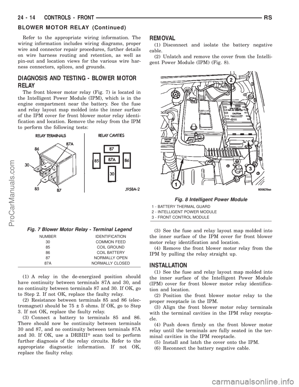
DIAGNOSIS AND TESTING - BLOWER MOTOR
RELAY
The front blower motor relay (Fig. 7) is located in
the Intelligent Power Module (IPM), which is in the
engine compartment near the battery. See the fuse
and relay layout map molded into the inner surface
of the IPM cover for front blower motor relay identi-
fication and location. Remove the relay from the IPM
to perform the following tests:
(1) A relay in the de-energized position should
have continuity between terminals 87A and 30, and
no continuity between terminals 87 and 30. If OK, go
to Step 2. If not OK, replace the faulty relay.
(2) Resistance between terminals 85 and 86 (elec-
tromagnet) should be 75 5 ohms. If OK, go to Step
3. If not OK, replace the faulty relay.
(3) Connect a battery to terminals 85 and 86.
There should now be continuity between terminals
30 and 87, and no continuity between terminals 87A
and 30. If OK, use a DRBIIItscan tool to perform
further diagnosis of the relay circuits. Refer to the
appropriate diagnostic information. If not OK,
replace the faulty relay.
REMOVAL
(1) Disconnect and isolate the battery negative
cable.
(2) Unlatch and remove the cover from the Intelli-
gent Power Module (IPM) (Fig. 8).
(3) See the fuse and relay layout map molded into
the inner surface of the IPM cover for front blower
motor relay identification and location.
(4) Remove the front blower motor relay from the
IPM by pulling the relay straight up.
INSTALLATION
(1) See the fuse and relay layout map molded into
the inner surface of the Intelligent Power Module
(IPM) cover for front blower motor relay identifica-
tion and location.
(2) Position the front blower motor relay to the
proper receptacle in the IPM.
(3) Align the front blower motor relay terminals
with the terminal cavities in the IPM relay recepta-
cle.
(4) Push down firmly on the front blower motor
relay until the terminals are fully seated in the ter-
minal cavities in the IPM receptacle.
(5) Install and latch the cover onto the IPM.
(6) Reconnect the battery negative cable.
Fig. 7 Blower Motor Relay - Terminal Legend
NUMBER IDENTIFICATION
30 COMMON FEED
85 COIL GROUND
86 COIL BATTERY
87 NORMALLY OPEN
87A NORMALLY CLOSED
Fig. 8 Intelligent Power Module
1 - BATTERY THERMAL GUARD
2 - INTELLIGENT POWER MODULE
3 - FRONT CONTROL MODULE
24 - 14 CONTROLS - FRONTRS
BLOWER MOTOR RELAY (Continued)
ProCarManuals.com
Page 2276 of 2399
The blower motor relay terminals are connected to
the vehicle electrical system through a receptacle in
the Intelligent Power Module (IPM). The inputs and
outputs of the compressor clutch relay include:
²The common feed terminal (30) receives a bat-
tery current input from the battery through a B(+)
circuit at all times.
²The coil ground terminal (85) receives a ground
input through the front/rear blower motor relay con-
trol circuit only when the FCM electronically pulls
the control circuit to ground.
²The coil battery terminal (86) receives a battery
current input from the battery through a B(+) circuit
at all times.
²The normally open terminal (87) provides a bat-
tery current output to the blower motor resistor
(manual heater-A/C control) or blower power module
(automatic heater-A/C control) through a fuse in the
IPM on the fused rear blower motor relay output cir-
cuit only when the blower motor relay coil is ener-
gized.
²The normally closed terminal (87A) is not con-
nected to any circuit in this application, but provides
a battery current output only when the blower motor
relay coil is de-energized.
Refer to the appropriate wiring information. The
wiring information includes wiring diagrams, proper
wire and connector repair procedures, further details
on wire harness routing and retention, as well as
pin-out and location views for the various wire har-
ness connectors, splices, and grounds.
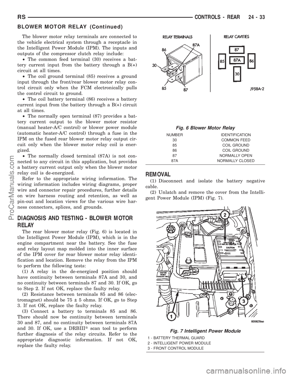
DIAGNOSIS AND TESTING - BLOWER MOTOR
RELAY
The rear blower motor relay (Fig. 6) is located in
the Intelligent Power Module (IPM), which is in the
engine compartment near the battery. See the fuse
and relay layout map molded into the inner surface
of the IPM cover for rear blower motor relay identi-
fication and location. Remove the relay from the IPM
to perform the following tests:
(1) A relay in the de-energized position should
have continuity between terminals 87A and 30, and
no continuity between terminals 87 and 30. If OK, go
to Step 2. If not OK, replace the faulty relay.
(2) Resistance between terminals 85 and 86 (elec-
tromagnet) should be 75 5 ohms. If OK, go to Step
3. If not OK, replace the faulty relay.
(3) Connect a battery to terminals 85 and 86.
There should now be continuity between terminals
30 and 87, and no continuity between terminals 87A
and 30. If OK, use a DRBIIItscan tool to perform
further diagnosis of the relay circuits. Refer to the
appropriate diagnostic information. If not OK,
replace the faulty relay.
REMOVAL
(1) Disconnect and isolate the battery negative
cable.
(2) Unlatch and remove the cover from the Intelli-
gent Power Module (IPM) (Fig. 7).
Fig. 6 Blower Motor Relay
NUMBER IDENTIFICATION
30 COMMON FEED
85 COIL GROUND
86 COIL GROUND
87 NORMALLY OPEN
87A NORMALLY CLOSED
Fig. 7 Intelligent Power Module
1 - BATTERY THERMAL GUARD
2 - INTELLIGENT POWER MODULE
3 - FRONT CONTROL MODULE
RSCONTROLS - REAR24-33
BLOWER MOTOR RELAY (Continued)
ProCarManuals.com