2002 CHRYSLER VOYAGER blower
[x] Cancel search: blowerPage 267 of 2399

CONDITION POSSIBLE CAUSES CORRECTION
COOLANT COLOR 1. Coolant color is not necessarily
an indication of adequate corrosion
or temperature protection. Do not
rely on coolant color for determining
condition of coolant.1. Check the freeze point of the
coolant. (Refer to 7 - COOLING/
ENGINE/COOLANT - DIAGNOSIS
AND TESTING) Adjust the ethylene
glycol-to-water ratio as necessary.
COOLANT LEVEL CHANGES IN
COOLANT BOTTLE.
TEMPERATURE GAUGE IS IN
NORMAL RANGE.1. Level changes are to be
expected as coolant volume
fluctuates with engine temperature.
The coolant level will also drop as
the system removes air from a
recent filling.1. A normal condition. No repair is
necessary.
Refer to (Fig. 1) when using the TEMPERATURE
GAUGE INDICATION DIAGNOSIS CHART.
TEMPERATURE GAUGE INDICATION DIAGNOSIS CHART
CONDITION POSSIBLE CAUSES CORRECTION
TEMPERATURE GAUGE READING
IS INCONSISTENT (FLUCTUATES,
CYCLES OR IS ERRATIC).1. Normal reaction to fan and/or
thermostat cycle (Fig. 1 ),
Examples B and C. During cold
weather operation with the heater
blower in the high position, the
gauge reading may drop slightly
(Fig. 1 ), Example D. Fluctuation is
also influenced by outside
temperature and heavy loads (Fig.
1 ), Example E.1. A normal condition. No correction
is necessary.
2. Gauge reading rises when
vehicle is brought to a stop after
heavy use (engine still running)
(Fig. 1 ), Example F.2. A normal condition. No correction
is necessary. Gauge reading should
return to normal range (Fig. 1 ),
Example A, after vehicle is driven.
3. Gauge reading high after
restarting a warmed-up (hot)
engine.3. A normal condition. No correction
is necessary. The gauge should
return to normal range (Fig. 1 ),
Example A, after a few minutes of
engine operation.
4. Temperature gauge or engine
coolant temperature sensor
defective or shorted. Also, corroded
or loose wiring in the electrical
circuit.4. Check operation of gauge or
engine coolant temperature sensor
and repair, if necessary.
7 - 18 ENGINERS
ENGINE (Continued)
ProCarManuals.com
Page 292 of 2399

CONDITION POSSIBLE CAUSES CORRECTION
6. Freeze point of antifreeze not
correct. Mixture may be too rich.6. Check antifreeze. Adjust
antifreeze-to-water ratio as
required.
7. Coolant not flowing through
system.7. Check for coolant flow in
coolant tank with engine warm
and thermostat open. Coolant
should be observed flowing
through the tank. If flow is not
observed, determine reason for
lack of flow and repair as
necessary.
8. Radiator or A/C condensor fins
are dirty or clogged.8. Clean debris from radiator or
A/C condensor
9. Radiator core is corroded or
plugged.9. Have radiator re-cored or
replaced.
10. Aftermarket A/C installed without
proper A/C condensor.10. Install proper A/C
condensor.
11. Dragging Brakes. 11. Check and correct as
necessary.
12. Non-factory bug screen is being
used reducing airflow.12. Only a factory screen
should be used.
13. Thermostat partially or
completely shut. This is more
prevalent on high mileage vehicles.13. Check thermostat and
replace if necessary.
14. Cylinder head gasket leaking. 14. Check cylinder head gasket
for leaks.
15. Heater core leaking. 15. Check heater cor for leaks.
Repair as necessary.
TEMPERATURE GAUGE
READING IS
INCONSISTENT
(FLUCTUATES, CYCLES
OR IS ERRATIC)1. During cold weather operation,
with the heater blower in the high
position, the gauge reading may
drop slightly. Fluctuation is also
influenced by loads, outside
temperature and extended idle time
with diesel engines.1. A normal condition. No
correction is necessary.
2. Temperature gauge or engine
mounted gauge sensor defective or
shorted. Also, corroded or loose
wiring in this circuit.2. Check operation of gauge
and repair as necessary.
3. Gauge reading rises when vehicle
is brought to a stop after heavy use
(engine still running).3. A normal condition. No
correction needed. Gauge
should return to normal range
after vehicle is driven.
4. Gauge reading high after starting
a warm-iup (hot) engine.4. A normal condition. No
correction needed. Gauge
should return to normal after a
few minutes of engine
operation.
RGCOOLING 2.5L TURBO DIESEL7a-3
COOLING 2.5L TURBO DIESEL (Continued)
ProCarManuals.com
Page 329 of 2399

(9) Disconnect the wire connectors from the back
of the radio.
INSTALLATION
(1) Connect wire harness to back of radio.
(2) Install bolt holding ground strap to the radio (if
equipped).
(3) Connect antenna cable to back of radio.
(4) Position radio into instrument panel.
(5) Install screws holding radio to instrument
panel.
(6) Install center instrument panel trim.
(7) Install trim panel above cupholder.
(8) Install cupholder.
(9) Connect battery negative cable.
RADIO NOISE SUPPRESSION
COMPONENTS
DESCRIPTION
Radio noise suppression devices are factory-in-
stalled standard equipment on this vehicle. Radio
Frequency Interference (RFI) and ElectroMagnetic
Interference (EMI) can be produced by any on-board
or external source of electromagnetic energy. These
electromagnetic energy sources can radiate electro-
magnetic signals through the air, or conduct them
through the vehicle electrical system.
When the audio system converts RFI or EMI to an
audible acoustic wave form, it is referred to as radionoise. This undesirable radio noise is generally man-
ifested in the form of ªbuzzing,º ªhissing,º ªpopping,º
ªclicking,º ªcrackling,º and/or ªwhirringº sounds. In
most cases, RFI and EMI radio noise can be sup-
pressed using a combination of vehicle and compo-
nent grounding, filtering and shielding techniques.
This vehicle is equipped with factory-installed radio
noise suppression devices that were designed to min-
imize exposure to typical sources of RFI and EMI;
thereby, minimizing radio noise complaints.
Factory-installed radio noise suppression is accom-
plished primarily through circuitry or devices that
are integral to the factory-installed radios, audio
power amplifiers and other on-board electrical com-
ponents such as generators, wiper motors, blower
motors, and fuel pumps that have been found to be
potential sources of RFI or EMI.
OPERATION
There are two common strategies that can be used
to suppress Radio Frequency Interference (RFI) and
ElectroMagnetic Interference (EMI) radio noise. The
first suppression strategy involves preventing the
production of RFI and EMI electromagnetic signals
at their sources. The second suppression strategy
involves preventing the reception of RFI and EMI
electromagnetic signals by the audio system compo-
nents.
The use of braided ground straps in key locations
is part of the RFI and EMI prevention strategy.
These ground straps ensure adequate ground paths,
particularly for high current components such as
many of those found in the starting, charging, igni-
tion, engine control and transmission control sys-
tems. An insufficient ground path for any of these
high current components may result in radio noise
caused by induced voltages created as the high cur-
rent seeks alternative ground paths through compo-
nents or circuits intended for use by, or in close
proximity to the audio system components or circuits.
Preventing the reception of RFI and EMI is accom-
plished by ensuring that the audio system compo-
nents are correctly installed in the vehicle. Loose,
corroded or improperly soldered wire harness connec-
tions, improperly routed wiring and inadequate audio
system component grounding can all contribute to
the reception of RFI and EMI. A properly grounded
antenna body and radio chassis, as well as a shielded
antenna coaxial cable with clean and tight connec-
tions will each help reduce the potential for reception
of RFI and EMI.
Fig. 9 ANTENNA TO RADIO
1 - RADIO
2 - LOCKING ANTENNA CONNECTOR
3 - INSTRUMENT PANEL ANTENNA CABLE
8A - 10 AUDIORS
RADIO (Continued)
ProCarManuals.com
Page 344 of 2399
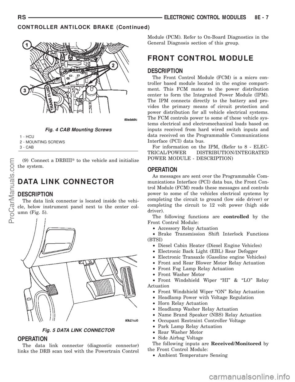
(9) Connect a DRBIIItto the vehicle and initialize
the system.
DATA LINK CONNECTOR
DESCRIPTION
The data link connector is located inside the vehi-
cle, below instrument panel next to the center col-
umn (Fig. 5).
OPERATION
The data link connector (diagnostic connector)
links the DRB scan tool with the Powertrain ControlModule (PCM). Refer to On-Board Diagnostics in the
General Diagnosis section of this group.
FRONT CONTROL MODULE
DESCRIPTION
The Front Control Module (FCM) is a micro con-
troller based module located in the engine compart-
ment. This FCM mates to the power distribution
center to form the Integrated Power Module (IPM).
The IPM connects directly to the battery and pro-
vides the primary means of circuit protection and
power distribution for all vehicle electrical systems.
The FCM controls power to some of these vehicle sys-
tems electrical and electromechanical loads based on
inputs received from hard wired switch inputs and
data received on the Programmable Communications
Interface (PCI) data bus.
For information on the IPM, (Refer to 8 - ELEC-
TRICAL/POWER DISTRIBUTION/INTEGRATED
POWER MODULE - DESCRIPTION)
OPERATION
As messages are sent over the Programmable Com-
munications Interface (PCI) data bus, the Front Con-
trol Module (FCM) reads these messages and controls
power to some of the vehicles electrical systems by
completing the circuit to ground (low side driver) or
completing the circuit to 12 volt power (high side
driver).
The following functions arecontrolledby the
Front Control Module:
²Accessory Relay Actuation
²Brake Transmission Shift Interlock Functions
(BTSI)
²Diesel Cabin Heater (Diesel Engine Vehicles)
²Electronic Back Light (EBL) Rear Defogger
²Electronic Transaxle (Gasoline engine Vehicles)
²Front and Rear Blower Motor Relay Actuation
²Front Fog Lamp Relay Actuation
²Front Washer Motor
²Front Windshield Wiper ªHIº & ªLOº Relay
Actuation
²Front Windshield Wiper ªONº Relay Actuation
²Headlamp Power with Voltage Regulation
²Horn Relay Actuation
²Headlamp Washer Relay Actuation
²Name Brand Speaker (NBS) Relay Actuation
²Occupant Restraint Controller Voltage
²Park Lamp Relay Actuation
²Rear Washer Motor
²Side Airbag Voltage
The following inputs areReceived/Monitoredby
the Front Control Module:
²Ambient Temperature Sensing
Fig. 4 CAB Mounting Screws
1 - HCU
2 - MOUNTING SCREWS
3 - CAB
Fig. 5 DATA LINK CONNECTOR
RSELECTRONIC CONTROL MODULES8E-7
CONTROLLER ANTILOCK BRAKE (Continued)
ProCarManuals.com
Page 561 of 2399

read and diagnose these trouble codes. Refer to the
Body Diagnostic Manual for a complete list of diag-
nostic routines.
NOTE: It may be possible to generate Sliding Door
Diagnostic Trouble Codes during normal power
sliding door operation. Refer to the Body Diagnos-
tic Manual for a complete list of diagnostic routines.
For additional information, (Refer to 8 - ELECTRI-
CAL/POWER DOORS - OPERATION). For a com-
plete power sliding door system wiring schematic,
refer to Wiring Diagrams. For power sliding door sys-
tem operation instructions, refer to the vehicle owner
manual.
WARNING: BE CERTAIN TO READ ALL WARNINGS
AND CAUTIONS IN POWER SLIDING DOOR OPER-
ATION BEFORE ATTEMPTING ANY SERVICE OF
POWER SLIDING DOOR SYSTEM OR COMPO-
NENTS.
OPERATION
With the push of a power sliding door open/close
command switch (key fob, overhead console or B-pil-
lar mounted) a signal is sent out to the Body Control
Module (BCM). The BCM then sends a signal out on
the PCI Data Bus circuit (J1850) to the power sliding
door module. The power sliding door module then
signals the power sliding door latch to release the
door to the unlatched and movable position. The
motor then starts an open cycle.During the door open cycle, if the power sliding
door module detects sufficient resistance to door
travel, such as an obstruction in the door's path, the
power sliding door module will immediately stop door
movement and reverse door travel to the full open or
closed position. The ability for the power sliding door
module to detect resistance to door travel is accom-
plished by hall effect sensors and the door motor
speed.
The power sliding door control module has the abil-
ity to learn. Anytime a door is opened or closed using
the power sliding door system the module learns
from its cycle. If a replacement power sliding door
component is installed or a door adjustment is made,
the module must re-learn the effort required to open
or close the door. A learn cycle can be performed with
a Diagnostic Scan Tool, such as the DRB IIIt, or with
a complete cycle of the door, using any one of the
command switches. Refer to Standard Procedures in
this section for detailed instructions.
The power sliding door system is designed with a
number of system inhibitors. These inhibitors are
necessary for safety and/or feasibility of the power
sliding door system. See the power sliding door sys-
tem inhibitors noted below:
POWER SLIDING DOOR SYSTEM INHIBITORS
²The power sliding door must be in thefullopen
or closed position in order for the power sliding door
system to start a cycle. If the door is not in this posi-
tion (based on the input from the full open, pawl or
ratchet switches) the door control module will not
respond to command switch inputs.
²The vehicles transmission must be inpark or
neutralin order for the power sliding door system to
start a cycle.
²The vehicles child lockout switch must be in the
ªUNLOCKEDº position in order for the power sliding
door systems B-pillar switches to function.
²If multiple obstacles are detected during the
same power open or close cycle the power sliding
door may go into full manual mode.
²If severe Diagnostic Trouble Codes (DTC) are
stored in the power sliding door control module the
power sliding door may go into full manual mode.
²Due to the high pressure created in the passen-
ger compartment with the blower motor on high, the
power sliding door may not complete a power close
cycle unless a window is cracked, allowing the pres-
sure to escape. This situation will only be experi-
enced on some vehicles, or vehicles with brand new
side door weather seals installed. Refer to the Side
Door Adjustment procedure in the Standard Proce-
dures section of this group.
²The vehicles fuel tank filler door must be in the
closed position. Due to the sliding door interference
Fig. 3 Power Side Door Fuse Location
8N - 20 POWER SLIDING DOOR SYSTEMRS
POWER SLIDING DOOR SYSTEM (Continued)
ProCarManuals.com
Page 613 of 2399

When the front airbag system is deployed, the fol-
lowingMUSTbe replaced:
²Complete Steering Column Assembly.
²Lower Steering Column Coupler.
²Steering Wheel.
²Clock Spring.
²Driver Airbag
²Passenger Airbag
²Upper Instrument Panel with Pad.
CARE OF UNDEPLOYED AIRBAGS
Airbags must be stored in their original special
container until used for service. At no time should a
source of electricity be permitted near the inflator on
the back of an airbag. When carrying or handling an
undeployed airbag, the trim side of the airbag should
be pointing away from the body to minimize possibil-
ity of injury if accidental deployment occurs. Do not
place undeployed airbag face down on a solid surface,
the airbag will propel into the air if accidental
deployment occurs.
STANDARD PROCEDURE - CLEAN UP
Roll or fold the driver airbag towards the steering
wheel and then tape the bag to the steering wheel.
Use a vacuum cleaner to remove any residual pow-
der from the vehicle interior. Work from the outside
in to avoid kneeling or sitting in a contaminated
area. Vacuum the heater and A/C outlets as well. If
HVAC was in RECIRC mode at time of airbag
deployment, operate HVAC blower on low speed/heat
and vacuum powder residue expelled from the heat
outlets. Multiple vacuum cleaning may be necessary
to decontaminate the interior of the vehicle.
REMOVAL
DEPLOYED AIRBAG
The Driver Airbag and Driver Airbag Cover/Horn
Pad are serviced separately from each other.
(1) Clean powder residue from interior of vehicle,
(Refer to 8 - ELECTRICAL/RESTRAINTS/DRIVER
AIRBAG - STANDARD PROCEDURE ) Cleanup.
(2) Remove two screws attaching Driver Airbag to
steering wheel.
(3) Remove the driver airbag from steering wheel.
(4) Disconnect wire connectors from Airbag and
Clock Spring.
(5) Adjust the steering wheel so that the tires are
in a straight ahead position. Remove steering wheel,
(Refer to 19 - STEERING/COLUMN/STEERING
WHEEL - REMOVAL)
(6) Disconnect the 2-way and 4-way connectors
between the clock spring and the instrument panel
wiring harness.(7) Remove upper and lower steering column
shrouds.
(8) Remove clock spring from the housing assem-
bly by depressing the 2 tabs on the clock spring.
UNDEPLOYED AIRBAG
(1) Remove screws attaching airbag/horn switch to
steering wheel.
(2) Remove Driver Airbag from steering wheel.
(3) Disconnect wire connectors from driver airbag
and clock spring.
INSTALLATION
DEPLOYED AIRBAG
(1) Perform cleanup procedure.(Refer to 8 - ELEC-
TRICAL/RESTRAINTS/DRIVER AIRBAG - STAN-
DARD PROCEDURE)
(2) Install a new steering column assembly and
lower steering column coupler. Refer to Steering, Col-
umn, Installation.
(3) Install the clock spring.
(4) Install the driver airbag and the two screws
retaining the airbag. Tighten screws to 10 N´m (90
in. lbs.)
WARNING: DO NOT CONNECT THE BATTERY NEG-
ATIVE CABLE. REFER TO ELECTRICAL,
RESTRAINTS, DIAGNOSIS AND TESTING - AIRBAG
SYSTEM FIRST.
UNDEPLOYED AIRBAG
(1) Position a new airbag into the airbag cavity.
(2) Install the two screws retaining the airbag.
Tighten screws to 10 N´m (90 in. lbs.)
WARNING: DO NOT CONNECT THE BATTERY NEG-
ATIVE CABLE. REFER TO ELECTRICAL,
RESTRAINTS, DIAGNOSIS AND TESTING - AIRBAG
SYSTEM FIRST.
DRIVER AIRBAG TRIM COVER
REMOVAL
The horn switch is integral to the driver airbag
trim cover. If either component is faulty or damaged,
the entire driver airbag trim cover and horn switch
unit must be replaced.
(1) Disconnect and isolate the battery negative
cable.
WARNING: WAIT TWO MINUTES FOR THE AIRBAG
SYSTEM RESERVE CAPACITOR TO DISCHARGE.
8O - 4 RESTRAINTSRS
DRIVER AIRBAG (Continued)
ProCarManuals.com
Page 615 of 2399

PASSENGER AIRBAG
DESCRIPTION
WARNING: NEVER DISASSEMBLE THE PASSEN-
GER AIRBAG, THE PASSENGER AIRBAG HAS NO
SERVICEABLE PARTS.
The Passenger Airbag is located beneath the
instrument panel and pad assembly. The airbag is
mounted to the back side of the instrument panel
reinforcement.
The instrument panel top pad is the most visible
part of the passenger airbag system. Located under
the instrument panel top pad are the airbag door, the
passenger airbag cushion and the airbag cushion
supporting components.
The passenger airbag includes a magnesium hous-
ing within which the cushion and inflator are
mounted and sealed.
Following a passenger airbag deployment, the pas-
senger airbag and the instrument panel must be
replaced. The passenger airbag cannot be repaired,
and must be replaced if deployed or damaged in any
way.
OPERATION
The passenger airbag is equipped with two infla-
tors, each with three levels of pressure output. The
inflators seal the hole in the airbag cushion so it can
discharge the gas it produces directly into the cush-
ion when supplied with the proper electrical signal.
Following an airbag deployment, the airbag cushion
quickly deflates by venting this gas through the
cushion material towards the instrument panel.
The passenger airbag is secured with screws to the
instrument panel beneath the instrument panel top
pad and above the glove box opening. The instrument
panel top pad above the glove box opening conceals
the airbag door and a predetermined hinge line
beneath its decorative cover. Upon airbag deploy-
ment, the top pad will bend at the hinge line and the
door will fold back out of the way onto the top of the
instrument panel.
When the front airbag system is deployed, the fol-
lowingMUSTbe replaced:
²Complete Steering Column Assembly.
²Lower Steering Column Coupler.
²Steering Wheel.
²Clock Spring.
²Driver Airbag.
²Passenger Airbag.
²Upper Instrument Panel with Pad.
CARE OF UNDEPLOYED AIRBAGS
Airbags must be stored in their original special
container until used for service. At no time should a
source of electricity be permitted near the inflator on
the back of an airbag. When carrying or handling an
undeployed airbag, the trim side of the airbag should
be pointing away from the body to minimize possibil-
ity of injury if accidental deployment occurs. Do not
place undeployed airbag face down on a solid surface,
the airbag will propel into the air if accidental
deployment occurs.
STANDARD PROCEDURE - CLEAN UP
Roll or fold the passenger airbag towards the
instrument panel surface and close the door over the
folded bag. Then tape the door shut.
Use a vacuum cleaner to remove any residual pow-
der from the vehicle interior. Work from the outside
in to avoid kneeling or sitting in a contaminated
area. Vacuum the heater and A/C outlets as well. If
HVAC was in RECIRC mode at time of airbag
deployment, operate HVAC blower on low speed/heat
and vacuum powder residue expelled from the heat
outlets. Multiple vacuum cleaning may be necessary
to decontaminate the interior of the vehicle.
REMOVAL
DEPLOYED AIRBAG
(1) Clean powder residue from interior of vehicle.
Refer to Electrical, Restraints, Passenger Airbag,
Standard Procedure - Passenger Airbag Clean Up.
(2) Remove instrument panel. Refer to Body,
Instrument Panel, Removal.
(3) Remove all reusable components from the
upper instrument panel and transfer to the new
instrument panel.
UNDEPLOYED AIRBAG
(1) Remove instrument panel. Refer to Body,
Instrument Panel, Removal.
(2) De-trim the instrument panel enough to gain
access to the passenger airbag fasteners.
(3) Disconnect yellow wire connector from passen-
ger airbag.
(4) Remove three bolts to the passenger airbag.
(5) Remove airbag from instrument panel through
rear of instrument panel.
INSTALLATION
DEPLOYED AIRBAG
Transfer all reusable components to the new
instrument panel.
(1) Install new Passenger Airbag into instrument
panel.
8O - 6 RESTRAINTSRS
ProCarManuals.com
Page 676 of 2399

8W-02 COMPONENT INDEX
Component Page
A/C Compressor Clutch Relay............ 8W-42
A/C Compressor Clutch................. 8W-42
A/C- Heater Control.................... 8W-42
A/C Pressure Sensor................... 8W-42
A/C-Heater Control.................... 8W-42
Accelerator Pedal Position Sensor......... 8W-30
Accessory Relay....................... 8W-10
Adjustable Pedals Module............... 8W-30
Adjustable Pedals Switch................ 8W-30
Airbag Control Module.................. 8W-43
Ambient Temp Sensor.................. 8W-49
Antenna............................. 8W-47
Auto Shut Down Relay................. 8W-30
Auto Temp Control..................... 8W-42
Automatic Day/Night Mirror............. 8W-49
Back-Up Lamp Switch.................. 8W-51
Battery Temperature Sensor............. 8W-20
Battery............................. 8W-20
Blend Door Actuators................... 8W-42
Body Control Module................... 8W-45
Boost Pressure Sensor.................. 8W-30
B-Pillar Switches...................... 8W-61
Brake Lamp Switch................. 8W-30, 51
Brake Transmission Shift Interlock
Solenoid........................... 8W-31
Cabin Heater Assist.................... 8W-30
Camshaft Position Sensor............... 8W-30
CD Changer.......................... 8W-47
Center High Mounted Stop Lamp......... 8W-51
Cinch/Release Motors................... 8W-61
Clockspring.................. 8W-33, 41, 43, 47
Clutch Pedal Interlock Switch Jumper..... 8W-10
Clutch Pedal Interlock Switch............ 8W-10
Combination Relays.................... 8W-54
Controller Antilock Brake............... 8W-35
Crank Case Ventilation Heater........... 8W-30
Crankshaft Position Sensor.............. 8W-30
Cylinder Lock Switches................. 8W-39
Data Link Connector................... 8W-18
Diagnostic Junction Port................ 8W-18
Door Ajar Switches.................... 8W-39
Door Lock Motor/Ajar Switches........... 8W-61
Door Lock Switches.................... 8W-61
Driver Airbag......................... 8W-43
EGR Solenoid......................... 8W-30
Electric Wiper De-Icer.................. 8W-48
Engine Control Module................. 8W-30
Engine Coolant Temp Sensor............. 8W-30
Engine Oil Pressure Switch.............. 8W-30
EVAP/Purge Solenoid................... 8W-30
Evaporator Temperature Sensor.......... 8W-42
Floor Console Lamp.................... 8W-44Component Page
Fog Lamps........................... 8W-50
Front Blower Module................... 8W-42
Front Blower Motor Relay............... 8W-42
Front Blower Motor.................... 8W-42
Front Cigar Lighter.................... 8W-41
Front Control Module.................. 8W-10
Front Fog Lamp Relay.................. 8W-50
Front Intrusion Sensor................. 8W-39
Front Washer Pump Motor.............. 8W-53
Front Wiper On/Off Relay............... 8W-53
Fuel Heater.......................... 8W-30
Fuel Injectors........................ 8W-30
Fuel Pressure Solenoid................. 8W-30
Fuel Pump Module.................... 8W-30
Full Open Switches.................... 8W-61
Fuselink............................. 8W-10
Fuses............................... 8W-10
Generator............................ 8W-20
Glow Plug Relay...................... 8W-30
Glow Plugs........................... 8W-30
Grounds............................. 8W-15
Halo Lamp........................... 8W-44
Headlamp Leveling Motors.............. 8W-50
Headlamp Switch...................... 8W-50
Headlamp Washer Relay................ 8W-53
Headlamps........................... 8W-50
Heated Seat Backs..................... 8W-63
Heated Seat Cushions.................. 8W-63
Heated Seat Modules................... 8W-63
High Beam Lamps..................... 8W-50
High Note Horn....................... 8W-41
Horn Relay.......................... 8W-41
Idle Air Control Motor.................. 8W-30
Ignition Coil.......................... 8W-30
Ignition Switch....................... 8W-10
Inlet Air Temperature Sensor............ 8W-30
Instrument Cluster.................... 8W-40
Instrument Panel Switch Bank . . 8W-44, 52, 53, 63
Integrated Power Module................ 8W-10
Knock Sensor......................... 8W-30
License Lamp......................... 8W-51
Lift Pump Motor...................... 8W-30
Liftgate Ajar Switch................. 8W-39, 61
Liftgate Cinch/Release Motor............. 8W-61
Liftgate Cylinder Lock Switch............ 8W-39
Liftgate Flood Lamps................... 8W-44
Liftgate Right Pinch Sensor.............. 8W-61
Low Beam Lamps.................... 8W-50-9
Manifold Absolute Pressure Sensor........ 8W-30
Mass Air Flow Sensor.................. 8W-30
Memory Seat/Mirror Module.......... 8W-62, 63
Memory Set Switch.................... 8W-63
RS8W-02 COMPONENT INDEX8W-02-1
ProCarManuals.com